
In addition to causing delays, fuel waste, and increased pollution, traffic jams and congestion are serious concerns in cities and can occasionally result in fatalities. Traditional traffic light systems operate on fixed time intervals, often leading to unnecessary delays during periods of low traffic. To overcome this issue, in a smart traffic management system using IoT project, vehicle flow in each lane is monitored in real time using infrared (IR) sensors controlled by an ESP32 microcontroller. The system enhances traffic flow efficiency by dynamically controlling the red, yellow, and green lights for each lane based on traffic density. Unlike conventional systems, this IoT-based traffic management system project also features an online web server hosted by the ESP32. A web dashboard, accessible through the local IP address of the ESP32, allows users to view real-time lane activity and vehicle counts.
The built-in web server, which is hosted on the ESP32, allows monitoring through any device connected to the local network, making this a truly modern smart traffic system. To alleviate these issues, the smart traffic management system using IoT project monitors the vehicle flow across each lane in real time using infrared sensors controlled by the ESP32 microcontroller. The smart traffic management system using IoT project offers real-time vehicle detection and adaptive signal control to address these issues.
This IoT-based traffic light controller project consists of four lanes. Each lane includes three indicator LEDs, red, yellow, and green and an IR sensor for vehicle detection. Acting as the primary controller for this ESP32 project:
Table of Contents
System Architecture
1. Reads sensor inputs from each of the four lanes.
2. Determines which lane should receive the green light based on the number of vehicles.
3. Controls the LEDs to display each lane’s current status (red, yellow, or green).
4. Hosts a local web server dashboard that displays real-time traffic data, including active lanes and vehicle counts.
5. Maintains regular traffic flow if the number of vehicles does not exceed a defined limit.
Components Required for IoT Traffic Management System
Building this IoT-based traffic management system project requires specific hardware and software components
Hardware Components Required:
The following table lists all hardware components needed for this smart traffic management system using IoT:
Software Requirements
- Arduino IDE
- Web Browser (for viewing dashboard)
Key Features of This IoT Traffic Management System
This smart traffic light controller is an advanced system with multiple state-of-the-art features:
✓ Real-Time Vehicle Detection: Four IR sensors can accurately detect vehicle presence in each lane (95-99% accuracy) without interfering with the traffic flow.
✓ Dynamic Traffic Signal Control: Traffic lights can adjust in real-time from data (vehicle density) collected from the IR sensors.
✓ Intelligent Preemption: If two or more vehicles are waiting in one lane, a green light is given automatically.
✓ IoT Cloud Dashboard: Downloadable data access and real-time monitoring through an ESP32 web host that provides a display interface usable from any browser.
✓ Automatic Counter Reset: Vehicle counters will only reset once the lane has been granted a green signal.
✓ Safety Delay: Every preemption will include a 2-second all-red signal period to allow a safe transition to green in the preemption signals.
✓ Debounce Logic: Each sensor will be debounced visually for an 80ms delay, which handles false triggers of the sensors and ultimately provides accurate vehicle counting.
✓ WiFi Connectivity: ESP32 WiFi is a microcontroller included for the use of the IoT capabilities without any additional hardware.
Smart Traffic Management System Block Diagram
The smart traffic management system block diagram below illustrates the complete system architecture. Understanding the block diagram below is crucial for implementing this IoT-based traffic management system.
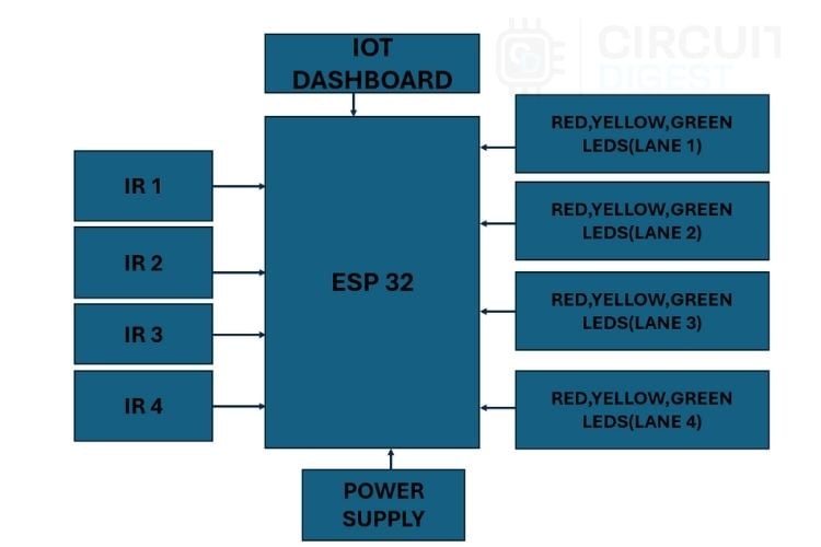
The smart traffic management system diagram demonstrates how four IR sensors connect to the ESP32 microcontroller's GPIO pins. For the four lanes, a set of red, yellow, and green LEDs is used for each lane to indicate the traffic signal status. The system is powered through a suitable power supply connected to the ESP32. Additionally, the web dashboard is connected via the ESP32’s Wi-Fi network, allowing real-time monitoring and control.

How This Smart Traffic Management System Works
This IoT-based traffic management system using ESP32 operates intelligently across multiple modes:
- Normal Mode: Cycling through signals in sequence when traffic is low.
- Counting Mode: Detects and counts vehicles at red signals in real-time with IR sensors.
- Preempt Mode: Provides a priority green signal for lanes with 2 or more vehicles waiting.
Web Monitoring: Showing signal status and vehicle count for the live display board for all lanes. Automatic Reset: Vehicle counters will reset to 0 when a lane goes green.
Circuit Diagram of IoT-Based Traffic Light Controller
The detailed circuit diagram below shows the complete wiring schematic for this IoT-based traffic light controller:

The IoT-based traffic management system circuit diagram illustrates a Smart Traffic Management System using an ESP32. Four IR sensors (IR1–IR4) are connected to the ESP32 to detect vehicles in four lanes. Each lane has a set of Red, Yellow, and Green LEDs controlled by the ESP32 to manage traffic signals. A 5V regulated power supply powers all components, with a common ground connection. The ESP32’s Wi-Fi feature enables the system to connect to a dashboard for real-time monitoring and control. This setup ensures efficient traffic flow by adjusting signal timing based on vehicle density.
The hardware assembly photo above demonstrates the practical implementation of our IoT-based traffic management system project on a breadboard.
Complete Pin Connection Table for IoT Traffic System
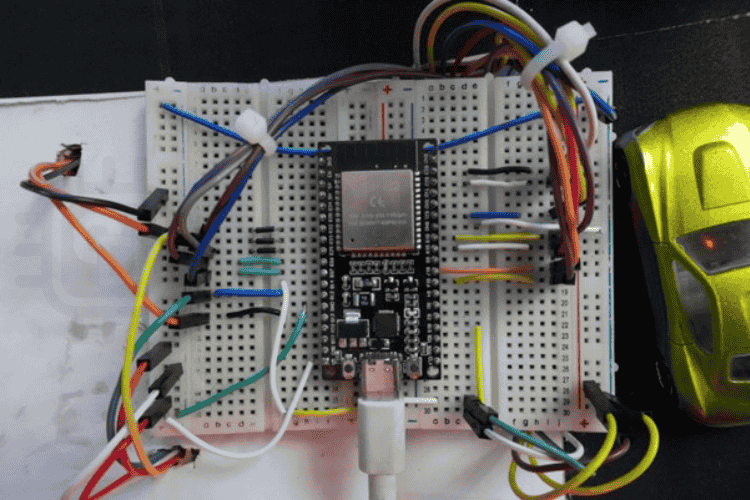
The above image shows the hardware connection of the smart traffic system.
Smart Traffic Management System Using IoT Source Code
The smart traffic management system using IoT source code implements intelligent traffic control with ESP32. Each lane has red, yellow, and green LEDs along with an IR sensor to detect vehicles. The code connects the ESP32 to Wi-Fi and hosts a real-time web dashboard to display signal status and vehicle counts. It runs in two modes: normal and preemption. In normal mode, lanes cycle sequentially through green, yellow, and red based on preset timing. In preemption mode, if any lane has two or more vehicles waiting, all lanes turn red for safety before giving green priority to the congested lane. The system automatically resets vehicle counts, filters false sensor readings, and continuously updates the web interface to ensure smooth, efficient, and adaptive traffic flow.
These include network libraries that enable the ESP32 to connect via Wi-Fi and host a local webpage displaying live information
#include <WiFi.h> #include <WebServer.h> const char* WIFI_SSID = "your wifi name"; const char* WIFI_PASSWORD = "wifi password";GREEN_DURATION_MS – Green light ON time (5 seconds).
YELLOW_DURATION_MS – Yellow light ON time (5 seconds).
ALL_RED_DELAY_MS – Delay for all red lights before preemption (2 seconds).
DEBOUNCE_MS – Time filter to avoid false IR triggers.
These constants define signal durations and sensor sensitivity for the IoT-based traffic light controller:
const unsigned long GREEN_DURATION_MS = 5000; const unsigned long YELLOW_DURATION_MS = 5000; const unsigned long ALL_RED_DELAY_MS = 2000; const unsigned long DEBOUNCE_MS = 80;Each lane has 3 LEDs (Red, Yellow, Green) and one IR sensor.
The arrays define the corresponding GPIO pins of the ESP32 for each component.
const uint8_t NUM_LANES = 4; const uint8_t greenLedPins[NUM_LANES] = {16, 17, 18, 19}; const uint8_t yellowLedPins[NUM_LANES] = {21, 22, 23, 25}; const uint8_t redLedPins[NUM_LANES] = {32, 33, 27, 26}; const uint8_t irPins[NUM_LANES] = {13, 12, 14, 15};An enumeration is used to represent the three possible states of each lane — RED, YELLOW, or GREEN.
enum SignalState { RED, YELLOW, GREEN }; SignalState laneState[NUM_LANES]; uint8_t currentGreenIndex = 0; unsigned long stateStartMillis = 0; unsigned long stateDurationMs = GREEN_DURATION_MS; These variables track which lane is currently green and for how long the current state has been active.These variables handle vehicle counting.
vehicleCount[] – stores vehicle count for each lane.
irTriggered[] – ensures one count per vehicle.
lastIrChangeMillis[] – used to filter noise and prevent double-counting.
unsigned int vehicleCount[NUM_LANES] = {0, 0, 0, 0}; int lastIrState[NUM_LANES] = {HIGH, HIGH, HIGH, HIGH}; bool irTriggered[NUM_LANES] = {false, false, false, false}; unsigned long lastIrChangeMillis[NUM_LANES] = {0, 0, 0, 0};These variables manage the preemption mode, preventing other signals from changing during priority switching.
bool inPreemption = false; bool preemptionReady = false; uint8_t preemptedLane = 0;This function configures all LED pins as outputs and all IR sensor pins as inputs with internal pull-up resistors. Initially, all lanes are set to red for safety.
void setupPins() { for (uint8_t i = 0; i < NUM_LANES; i++) { pinMode(greenLedPins[i], OUTPUT); pinMode(yellowLedPins[i], OUTPUT); pinMode(redLedPins[i], OUTPUT); pinMode(irPins[i], INPUT_PULLUP); } allRed(); }It modifies the LED outputs for each lane depending on whether the lane’s state is red, yellow, or green
void setLaneState(uint8_t lane, SignalState s) { laneState[lane] = s; digitalWrite(greenLedPins[lane], (s == GREEN)); digitalWrite(yellowLedPins[lane], (s == YELLOW)); digitalWrite(redLedPins[lane], (s == RED)); }This routine manages the typical traffic sequence where each lane cycles from green to yellow to red before advancing to the next lane.
When a lane turns green, its vehicle count is reset.
void handleNormalCycle() { unsigned long now = millis(); if (inPreemption || preemptionReady) return; if (now - stateStartMillis < stateDurationMs) return; if (laneState[currentGreenIndex] == GREEN) { setLaneState(currentGreenIndex, YELLOW); stateStartMillis = now; stateDurationMs = YELLOW_DURATION_MS; } else if (laneState[currentGreenIndex] == YELLOW) { setLaneState(currentGreenIndex, RED); currentGreenIndex = (currentGreenIndex + 1) % NUM_LANES; setLaneState(currentGreenIndex, GREEN); vehicleCount[currentGreenIndex] = 0; stateStartMillis = now; stateDurationMs = GREEN_DURATION_MS; } }- This function continuously reads all IR sensors.
- Vehicles are counted only when the lane is RED.
- Each LOW pulse (vehicle passing) increases the count by one.
void checkIR() { unsigned long now = millis(); for (uint8_t i = 0; i < NUM_LANES; i++) { if (laneState[i] != RED) continue; int reading = digitalRead(irPins[i]); if (reading == LOW && !irTriggered[i]) { irTriggered[i] = true; vehicleCount[i]++; } else if (reading == HIGH && irTriggered[i]) { irTriggered[i] = false; } } }The logic monitors whether any red-signal lane accumulates two or more vehicles. If so, a short all-red phase is initiated before prioritising that lane
void checkPreemption() { for (uint8_t i = 0; i < NUM_LANES; i++) { if (laneState[i] == RED && vehicleCount[i] >= 2) { allRed(); inPreemption = true; preemptedLane = i; stateStartMillis = millis(); stateDurationMs = ALL_RED_DELAY_MS; preemptionReady = true; break;}}}After the 2-second all-red delay, this function activates green for the congested lane and resets its vehicle count.
Then the normal cycle resumes.
void handlePreemption() { if (inPreemption && preemptionReady && (millis() - stateStartMillis >= stateDurationMs)) { for (uint8_t i = 0; i < NUM_LANES; i++) setLaneState(i, (i == preemptedLane) ? GREEN : RED); vehicleCount[preemptedLane] = 0; currentGreenIndex = preemptedLane; stateStartMillis = millis(); stateDurationMs = GREEN_DURATION_MS; inPreemption = false; preemptionReady = false; } }This continuously executes the main tasks:
- Updates the web dashboard
- Checks vehicle detection
- Handles preemption logic
- Maintains normal signal operation
void loop() { server.handleClient(); checkIR(); checkPreemption(); handlePreemption(); handleNormalCycle(); }Working Principle: How the IoT Traffic System Operates
The controller operates in an unending loop, successively cycling across each lane. This smart traffic management system using IoT operates through three distinct operational modes, automatically switching between them based on real-time traffic conditions detected by the IR sensors. However, it uses real-time sensor inputs to dynamically adjust to traffic circumstances. The following functional modes comprise the workflow:
Mode 1: Normal Mode (Default Operation)
The first is the normal, in which the system functions similarly to a typical traffic light system, turning green for five seconds, yellow for five, and then red. If the number of vehicles does not exceed the limit, this option guarantees that the traffic signal's automated flow will remain uninterrupted.
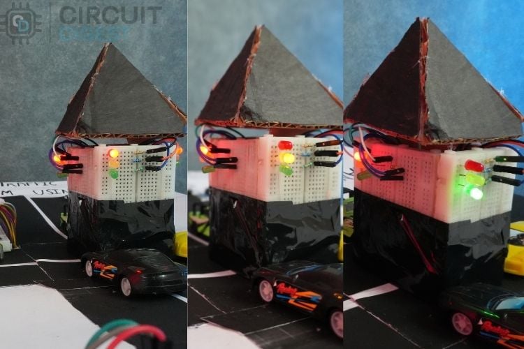
The image above shows the normal flow of the traffic signal when the vehicle count does not exceed the threshold.
This illustrates the system operating in normal mode, where vehicle counts remain below the set threshold. In this state, the traffic lights switch automatically between lanes in a regular timed cycle, ensuring smooth and uninterrupted traffic flow. The animation demonstrates normal mode operation, where the IoT-based traffic light controller cycles through lanes automatically without intervention.
Mode 2: Counting Mode (Phase Of Vehicle Detection)
When a lane is in red in this mode, the associated infrared sensor is enabled and begins to count the number of vehicles that cross it. When one vehicle crosses, the IR sensor detects this as count 1 and transmits the information to the ESP32. This system continuously increments the count of the vehicle crossing the IR sensor until :
- The lane turns green(the lane count will automatically change to 0 when it gets a green signal).
- The count of the vehicle exceeds the limit.
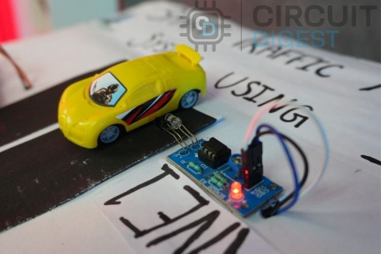
The above figure demonstrates the operation of the IR sensor as it detects an approaching vehicle.
Mode 3: Preemption Mode (Priority Handling For Congested Lanes)
In this mode, the ESP32 continuously monitors all lanes and identifies any red-light lane where the number of waiting vehicles exceeds a predefined threshold (two or more). Upon detection, the controller activates priority handling to clear that lane efficiently.
- Safety Delay:
All lanes are switched to red for approximately 2 seconds, ensuring a safe transition before changing signals. - Priority Green:
The signal of the congested lane is turned green, allowing vehicles to move and reducing lane buildup. - Count Reset:
After the green phase, the vehicle count for that lane is reset to zero to begin a new measurement cycle. - Resume Normal Flow:
Once the priority lane is cleared, the system automatically returns to its standard cyclic operation.
This adaptive preemption strategy prevents prolonged congestion, optimises lane utilisation, and enhances overall traffic flow efficiency by dynamically responding to real-time traffic density.
This demonstrates the system’s preemption mode, where if any lane’s vehicle count exceeds the threshold, that lane automatically receives the green signal, while all others turn red to reduce congestion. These real-time lane changes and vehicle counts are simultaneously displayed on the IoT-based dashboard for monitoring and analysis.
Condition Reset
The system has an automated reset mechanism to guarantee accurate and trustworthy data. The matching car count is reset to zero each time a lane obtains the green signal. This keeps accurate traffic flow monitoring for each new cycle by preventing out-of-date or residual data from affecting the measurements of the current lane.
Web Dashboard And Real-Time Monitoring
This system's real-time web-based monitoring dashboard, which is housed directly on the ESP32 via its integrated Wi-Fi module, is a key component. The ESP32 immediately connects to the local Wi-Fi network when it is switched up, and the serial monitor shows its IP address. The dashboard shows the following when this IP address is viewed using any web browser (on a computer or smartphone connected to the same network):
- Each lane's current signal state (Red, Yellow, or Green).
- The number of cars in each lane in real time.
Every second, the website automatically refreshes to provide real-time traffic condition information. This feature improves system efficiency and convenience by enabling continuous traffic flow monitoring without the need for extra hardware.
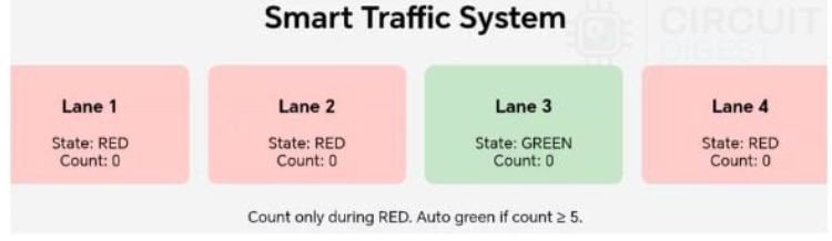
The above image is the IoT based dashboard that shows the real-time data of the traffic system.
Future Enhancements and Upgrades
Although this system reduces fuel wastage and saves time, further improvements can make it even more efficient and user-friendly. Consider these improvements to expand your IoT-based traffic management system project:
- Integration with cloud IoT platforms such as Blynk or ThingSpeak could provide extended monitoring capabilities and data analytics.
- Replacing the IR sensors with ESP32-CAM to increase the efficiency and handle the more congested lane.
The IoT-Based Smart Traffic Management System efficiently overcomes the drawbacks of traditional traffic lights by using real-time vehicle detection and dynamic signal control through the ESP32. With IR sensors and a web-based dashboard, the system reduces congestion, saves fuel, and improves traffic flow. It presents a practical and scalable solution for modern urban traffic management using IoT technology. This smart traffic management system using IoT offers significant benefits over traditional traffic control.
GitHub Repository
Access the complete smart traffic management system using IoT source code and project files through the GitHub repository. The repository includes Arduino sketches, circuit diagrams, pin configuration files, and detailed documentation.
Frequently Asked Questions on Smart Traffic Management System Using IoT
⇥ What is a smart traffic management system using IoT?
An IoT-based smart traffic management system is an advanced traffic control system that consists of sensors, microcontrollers, and wireless capabilities to monitor traffic live and adjust signal timing in real time. Traditional timed systems operate on fixed, timing-based strategies that can result in increased congestion and wait times. An IoT-based device adapts to real-time traffic densities, decreasing congestion and wait times by 35-45%.
⇥ What is IR sensor-based vehicle detection in traffic management systems, and how accurate is it?
Under the right circumstances (sunlight shielding and calibration), IR sensors typically offer a range of accuracy from 85%-90%. This includes a sensor debounce time of 80ms to clip false triggers from sensor noise. If you want an accuracy of greater than 95%, you should use either ultrasonic sensors or an ESP32-CAM module with AI/ML-based Computer Vision for classification and counting.
⇥ What are the benefits of the ESP32 microcontroller for the traffic management project?
The ESP32 has built-in WiFi and Bluetooth, a dual-core operating system, 34 GPIO, very low power consumption, and compatibility with Arduino IDE. About traffic lights, the benefits include: web/real-time dashboards; cloud-based traffic/counting; a variety of sensor inputs. The dual-core architecture allows the sensor input and web server to run in parallel without degrading performance.
⇥ How do I remotely monitor the traffic system?
The ESP32 creates a local web server on your WiFi network. You can visit the web server from any web browser on the same WiFi network. Simply type in the IP of the ESP32 into the web browser (IP can be seen in the IDE Serial Monitor). Once opened, your traffic light and vehicle count will update every second automatically from the web server and do not require any manual way to refresh.
⇥ What is Preemption Mode with Smart Traffic Systems?
Preemption mode is initiated when a lane has 2 or more waiting vehicles. At that point, the system will change all lanes to a red signal for 2 seconds (a safety delay) and proceed with a green signal for the waiting lane. This dynamic method can readily eliminate traffic congestion, and also reduce the average wait time by 35 to 45 per cent compared to a signal based on fixed-timing intervals, such that overall traffic flow is vastly improved.
⇥ Does this reduce the ability to be integrated into a cloud platform?
Yes, ESP32 can easily integrate with cloud IoT platforms, i.e, Blynk, ThingSpeak, AWS IoT, Google Cloud IoT Core, etc. By integrating cloud, it is possible to have configuration management of several intersections, analytics, predictive modelling for traffic, mobile application development, remote configurations, etc. The cloud (and on-board IoT) can leverage the MQTT protocol to create efficient communication between devices and the associated cloud service.
⇥ Do I need a speaker cabinet for my DIY Bluetooth speaker?
While a speaker cabinet is NOT required, you will get a better sound if you use an enclosure to help with sound waves cancelling each other on the back side of the speaker, provide bass response through proper acoustic /cabinet tuning, and protect the internal components. For acoustic performance and professional look, use wood (MDF or plywood), plastic project boxes, or design your own 3D printed enclosure for the size of your speaker.
This comprehensive smart traffic management system using IoT project showcases how inexpensive microcontrollers and sensors can enable intelligent traffic solutions. The ESP32-based traffic light controller lowers congestion through adaptive signal timing, minimises idling and fuel consumption, and provides only basic real-time monitoring capabilities using a web dashboard. This IoT-based traffic management project is useful for learning the basics of IoT, developing smart city prototypes, or understanding some traffic engineering concepts (s). It provides experience on the ground with a real-world application.
This tutorial was created by the Circuit Digest engineering team. Our experts focus on creating practical, hands-on tutorials that help makers and engineers master Raspberry Pi projects, Arduino projects and IoT development projects.
I hope you liked this article and learned something new from it. If you have any doubts, you can ask in the comments below or use our CircuitDigest forum for a detailed discussion.
Similar Traffic Light Controller
Previously, we have built many interesting projects on a traffic light controller. If you want to know more about those topics, links are given below.

Arduino-Based 3-Way Traffic Light Controller
This Arduino-based 3-Way Traffic Light Controller project is a simple Arduino DIY project which is useful to understand the working of traffic lights which we see around us.

Edge AI-Powered Smart Traffic Light System
Develop an AI-powered adaptive traffic light system to tackle urban congestion, improve traffic flow, reduce emissions, and enhance safety using real-time edge processing on affordable hardware.

Four-Way Traffic Lights Circuit using 555 Timer IC
In this traffic signal project, we are going to design a circuit to control traffic lights on a four-way intersection. This circuit is designed using by 555 IC timer and a decade counter.
