Here's a circuit you could try: -
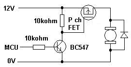
The MCU drives the BJT which in turn switches-on a P channel FET. When drive is removed to the BJT, the motor switches off. The diode across the motor is to protect against back-emfs when the motor feed is removed.
A simpler (non ground referenced) circuit that can be used is this: -
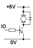
The picture shows a 5V supply but it can run from 12V - note the diode across the motor again.
Decisions There are a couple of things you have to decide. Firstly and importantly, do you need to reverse the direction of the motor? If you do then if it is your first project in this area, maybe relays are the choice - they lend themselves for being wired as motor reverse circuits BUT, you could find an IC or circuit that performs what is known as a "H bridge". It uses transistors like relay contacts and works fine for motor reversing.
You also need to decide what your motor power requirements are so that you can pick the transistor that is able to deliver the power to your motor most efficiently without getting hot and frying.
moderator's note: This answer had arrived to this thread as a result of a merge.