Arduino 上手教程
2. 设备开发 & 案例程序
3. M5Unified
4. M5GFX
5. 拓展模块
Unit
Base
Cap
IoT
Stamp-Pico Arduino 示例程序编译与烧录
1.准备工作
- 1.Arduino IDE安装: 参考Arduino IDE安装教程,完成IDE安装。
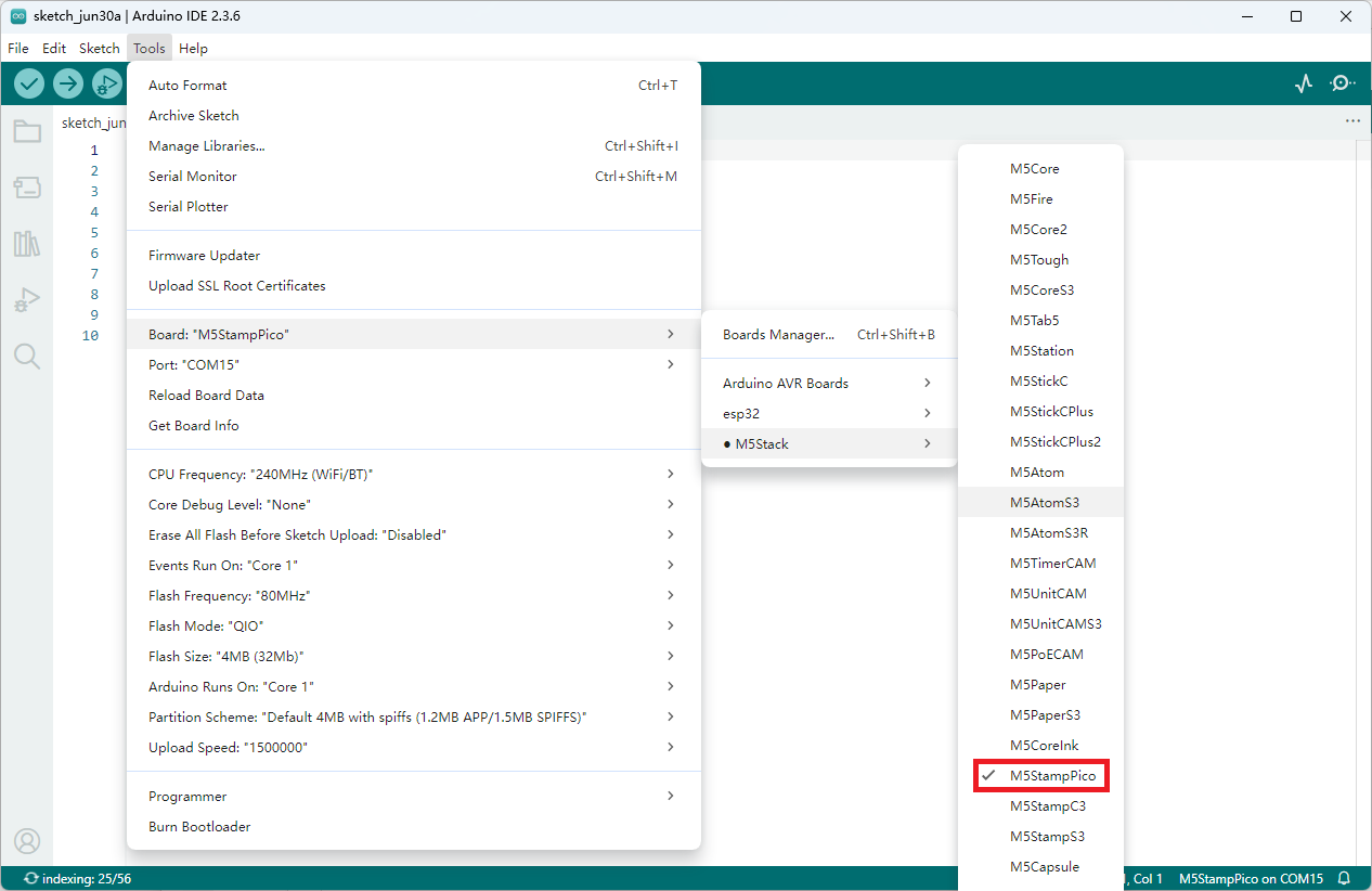
- 2.板管理安装: 参考基本环境搭建教程,完成M5Stack板管理安装并选择开发板
M5StampPico。
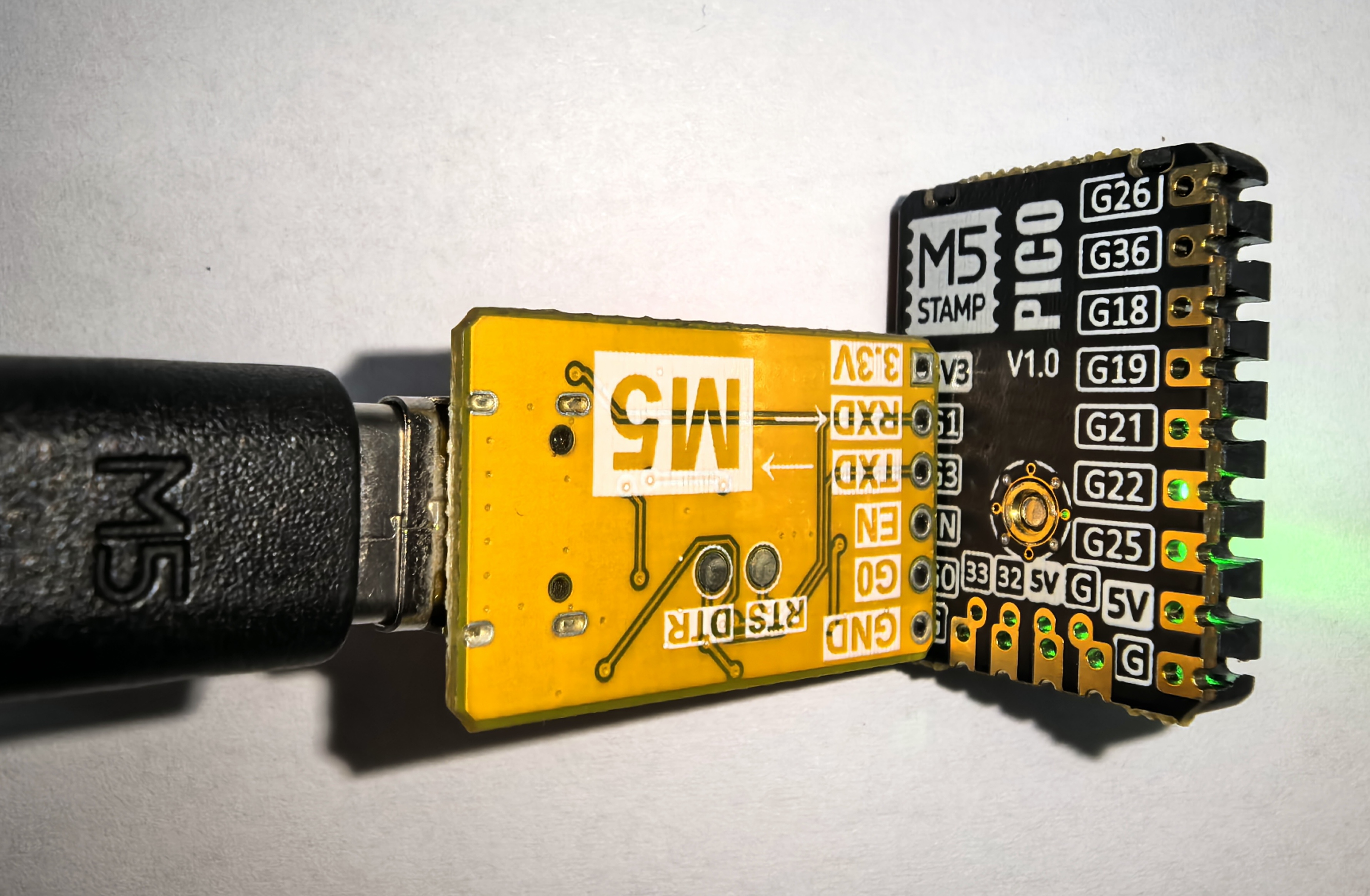
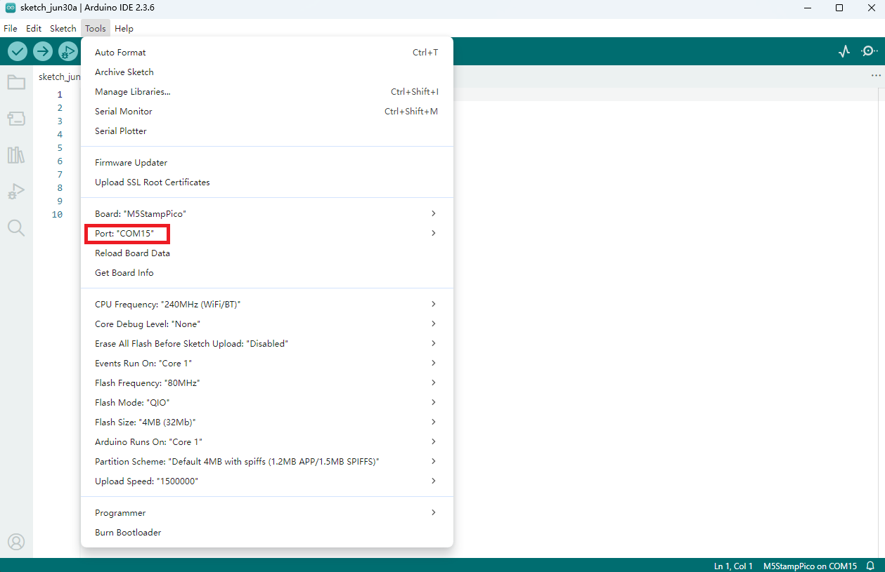
2.端口选择
将设备通过USB线及USB-TTL转接板连接至电脑,在Arduino IDE中可选中对应设备的端口。
3.程序编译&烧录
在Arduino IDE 工作区输入下方代码, 点击上传按钮,将自动进行程序编译与烧录。
cpp
1 2 3 4 5 6 7 8 9 10 11 12 13 14 15 16 17 18 19 20 21 22 23 24 25 26 27 28 29 30 31 32 33 34 35 36 37 38 39 40 41 42 43 44 45 46 47 48 49 50 51 52 53 54
#include <Arduino.h> #include <FastLED.h> #define PIN_BUTTON 39 #define PIN_LED 27 #define NUM_LEDS 1 CRGB leds[NUM_LEDS]; uint8_t led_ih = 0; uint8_t led_status = 0; String led_status_string[] = {"Rainbow", "Red", "Green", "Blue"}; void setup() { Serial.begin(115200); Serial.println("Stamp-Pico demo!"); pinMode(PIN_BUTTON, INPUT); FastLED.addLeds<WS2812, PIN_LED, GRB>(leds, NUM_LEDS); } void loop() { switch (led_status) { case 0: leds[0] = CHSV(led_ih, 255, 255); break; case 1: leds[0] = CRGB::Red; break; case 2: leds[0] = CRGB::Green; break; case 3: leds[0] = CRGB::Blue; break; default: break; } FastLED.show(); led_ih++; delay(15); if (!digitalRead(PIN_BUTTON)) { delay(5); if (!digitalRead(PIN_BUTTON)) { led_status++; if (led_status > 3) led_status = 0; while (!digitalRead(PIN_BUTTON)) ; Serial.print("LED status updated: "); Serial.println(led_status_string[led_status]); } } }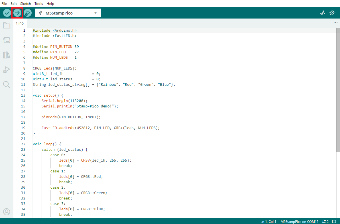
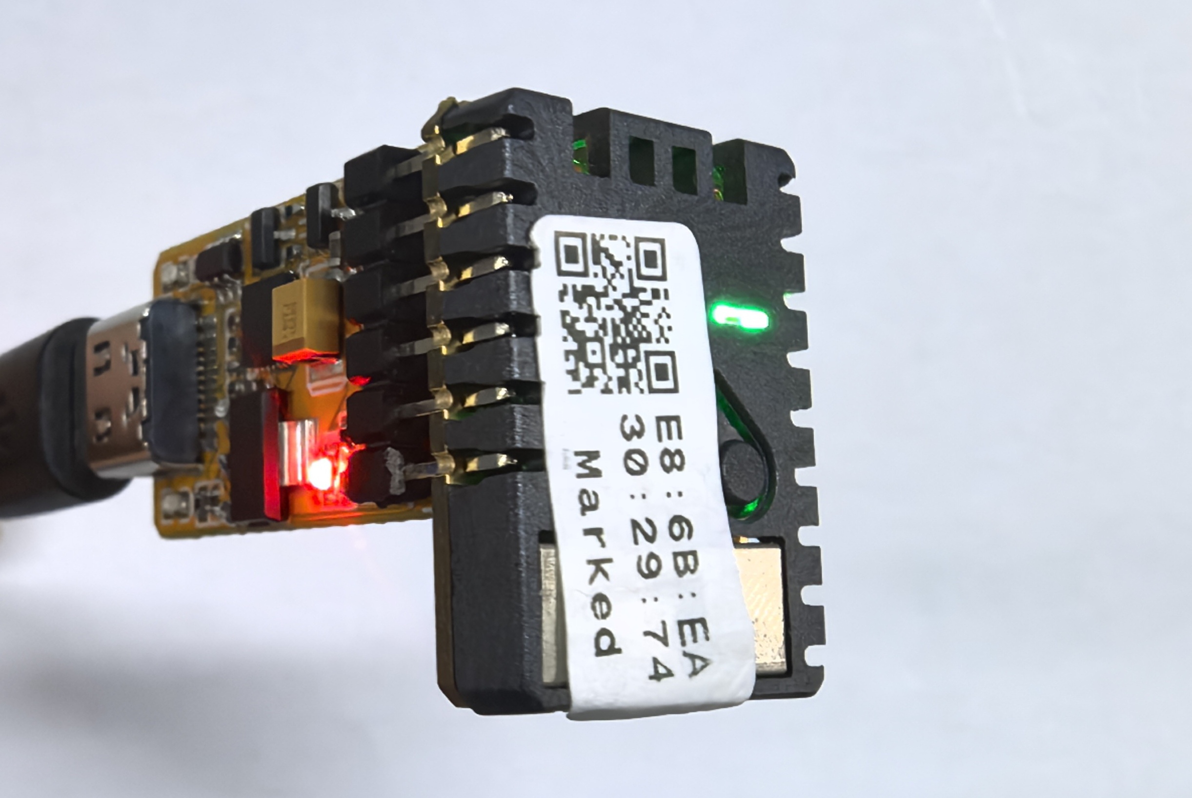
上传代码后,Stamp-Pico 设备上的 RGB LED 灯将自动亮起。通过按动按钮可循环切换 LED 的显示颜色,同时设备会通过串口输出当前的灯光状态信息(如颜色值或模式),方便调试与交互反馈。