In this tutorial you will learn how to get started with the LILIGO T-Camera S3 board.
The LILYGO T-Camera S3 is a compact development board built around the ESP32-S3 FN16R8 dual-core microcontroller, paired with an OV2640 camera module, 8 MB PSRAM, and 16 MB flash memory.
In this article we will walk through the essential setup steps, such installing the libraries, the ESP32 core and preparing the code for a webserver that streams video data over Wi-Fi from the T-Camera S3 to your Web browser.
Required Parts
You will need a T-Camera S3 and a USB-C cable to program the board and to try out the code examples. The following links show you where to get them.
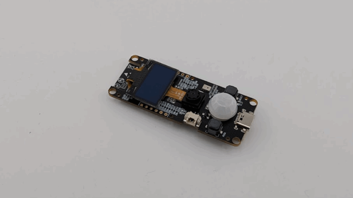
LILYGO T-Camera S3
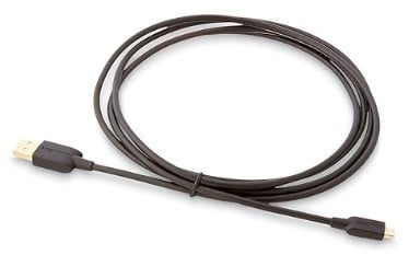
USB C Cable
Makerguides is a participant in affiliate advertising programs designed to provide a means for sites to earn advertising fees by linking to Amazon, AliExpress, Elecrow, and other sites. As an Affiliate we may earn from qualifying purchases.
Hardware of the T-Camera S3
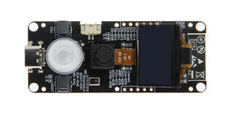
The LILYGO T-Camera S3 is a development board that uses the ESP32‑S3FN16R8 dual-core microcontroller. This SoC runs at up to 240 MHz and includes vector extension support, making it suited for machine learning and vision-related tasks. The board incorporates 8 MB of PSRAM and 16 MB of flash memory, allowing for storage of models, images or logging data.

Components
For image capture, the board integrates a 2 megapixel OV2640 camera module (with UXGA 1622×1200 resolution) as standard; an optional 5 megapixel version is also available. A small monochrome OLED display (0.96 inch, 128×64 pixels) driven via SSD1306 over I²C is included, offering a simple visual interface or status display. On the audio side, a microphone is present and a PIR motion sensor provides basic motion detection capabilities on the board.
Connectivity
Connectivity is handled by the ESP32-S3’s integrated 2.4 GHz WiFi (802.11 b/g/n) and Bluetooth 5 (LE) radios, enabling wireless communication and remote access. A USB-C port provides power supply and programming/debugger access, and a 5-pin JST header offers additional I/O access such as GPIO, UART, 3.3 V/5 V and ground. The board’s dimensions are approximately 69 × 28 × 18.5 mm. The picture below shows the Pinout of the board:

Power
Power management includes support for USB power supply and a JST-GH connector for a single-cell Li-Po battery, making the board suitable for portable deployments. The board also exposes a boot and a power button.
Technical Specification
The following table summarizes the technical specification of the LILYGO T-Camera S3 board:
| Parameter | Specification |
|---|---|
| Microcontroller | ESP32-S3FN16R8 dual-core (Tensilica LX7, up to 240 MHz) |
| PSRAM | 8 MB |
| Flash Memory | 16 MB |
| Camera Module | OV2640 (2 MP, UXGA 1622×1200) standard; optional 5 MP variant |
| Display | OLED 0.96″, 128×64 pixels, SSD1306 over I²C |
| Wireless Connectivity | WiFi 2.4 GHz 802.11 b/g/n; Bluetooth 5.0 LE |
| Motion Sensor | PIR (passive infrared) |
| Audio Input | On-board microphone |
| Power Supply & Charging | USB-C port; JST-GH Li-Po battery connector |
| Board Dimensions | Approx. 69 × 28 × 18.5 mm (board); 75 × 35 × 12 mm (with enclosure) |
| Programming Interfaces & I/O | USB-C for program |
Installation of Libraries
In this section we will install the libraries needed to compile code for the T-Camera S3 board. Go to LILYGO github repo for the display at LilyGo-Cam-ESP32S3. Click on the green “<> Code” button and then “Download ZIP” to download the repo as a ZIP file:

Next unpack the ZIP file to extract it contents. You should see the following files in the unpacked folder named “LilyGo-Cam-ESP32S-master”:

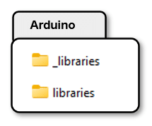
We need to copy the contents of the “lib” folder into the “libraries” folder for the Arduino IDE. Under Windows the “libraries” folder is typically located under:
C:\Users\<username>\OneDrive\Documents\Arduino\libraries
Since this folder already contains installed libraries, I recommend you temporarily rename it, e.g. to “_libraries” and create a new folder named “libraries”. This way you avoid conflicts with your already installed libraries and you don’t loose them either. Later you can easily revert this change. The picture below shows how your “Arduino” folder with the libraries should look like:
Next we copy the files in the “lib” folder into the new “libraries” folder as shown below:

That completes the installation of the required libraries (AceButton, ESP32QRCodeReader, U8g2, XPowersLib). In the next section we install the ESP32 core.
Installation of ESP32 core
Apart from the libraries we also need to install a specific version of the ESP32 core. The github repo for the T-Camera S3 states that the Version 2.0.17 should be used. It seems that the current version (3.3.x) is not supported (as of Nov 2025) and the code will not compile – though I did not test this.
Downgrading the version of the ESP32 is easy. Open the BOARDS MANAGER, enter “ESP32” to filter for ESP32 boards and then select Version 2.0.17 for the esp32 by Espressif Systems. The picture below shows how this looks like after downgrading the ESP32 core:

Now we are almost ready to try out the camera.
Code for Minimal Camera Example
In this section we will prepare, flash and run the code for the Minimal Camera Example that can be found in the examples folder of the github repo. Since we downloaded the github repo, you have the example code already on your computer. Open the “LilyGo-Cam-ESP32S-master” on your computer, then go to “examples” and then open the “MinimalCameraExample” folder:

There are a few things we need to change to be able to run the MinimalCameraExample.ino, though
Rename Secrets File
First, let us rename the file “secrets.h.example” to “secrets.h”, since we need this file for the WiFi credentials:

Fill in Secrets
If you now open the MinimalCameraExample.ino project in your Arduino IDE you should see a Tab with the “secrets.h” file.

Click on it and enter the SSID and Password for your WiFi. You can fill in the same SSD and Password three times:
// If using station mode, please fill in the wifi ssid and password here, cahnge as per your wireless settings #define WIFI_SSID1 "ssid_from_AP_1" #define WIFI_SSID_PASSWORD1 "your_password_for_AP_1" #define WIFI_SSID2 "ssid_from_AP_2" #define WIFI_SSID_PASSWORD2 "your_password_for_AP_2" #define WIFI_SSID3 "ssid_from_AP_3" #define WIFI_SSID_PASSWORD3 "your_password_for_AP_3"
Select WiFi mode
Finally, we need to make two changes in the MinimalCameraExample.ino file. Replace the angular brackets for the include of secrets.h by quotation marks and set the use_ap_mode flag to false:
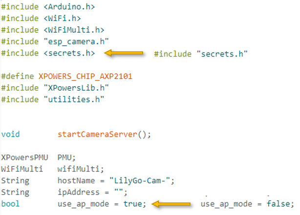
After these changes, the beginning of the MinimalCameraExample.ino file should look like this:
#include <Arduino.h> #include <WiFi.h> #include <WiFiMulti.h> #include "esp_camera.h" #include "secrets.h" #define XPOWERS_CHIP_AXP2101 #include "XPowersLib.h" #include "utilities.h" void startCameraServer(); XPowersPMU PMU; WiFiMulti wifiMulti; String hostName = "LilyGo-Cam-"; String ipAddress = ""; bool use_ap_mode = false;
Upload Code to T-Camera S3
Now we are almost ready to upload the code to the T-Camera S3. Select “ESP32S3 Dev Module” as board and make sure it is connected and recognized at an COM port:

Next under the “Tools” menu set the following parameters:
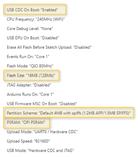
Most important are Flash Size, Partition Scheme and PSRAM. The other parameters should be the default settings but you better check. When printing to the Serial Monitor the USB_CDC_ON_BOOT configuration needs to be turned on.
Now you can upload the code to your T-Camera S3 and hopefully see the following information on the Serial Monitor:

It tells you that the board could connect to the WiFi and at which IP address the Webserver for the camera is running. The error messages regarding the partitioning doesn’t seem to cause issues and can be ignored.
Open your Webbrowser, enter the IP Address, e.g. “192.168.1.111” in the address bar and a sidebar with a menu for the webserver should appear:

Click on “Start Stream” at the bottom of that menu (just above Advanced Settings):

and you should be able to enjoy a video stream in your browser:

If that all worked, congratulations ; )
Can’t upload code to T-Camera S3
I found that uploading the code for the MinimalCameraExample to the T-Camera S3 often doesn’t work. Holding the Boot/Resetting button, resetting the board, restarting the computer – nothing worked.
The flashing started successfully but then before reaching 100% failed with the the error message:
A serial exception error occurred: Cannot configure port, something went wrong. Original message: PermissionError(13, ‘The device does not recognize the command.’, None, 22)
Note: This error originates from pySerial. It is likely not a problem with esptool, but with the hardware connection or drivers.
Good news is, I found a way to overcome this issue. Just setup another Arduino project with minimal code and flash that code if you encounter the above error:
void setup() { Serial.begin(115200); } void loop() { delay(1000); Serial.println("loop"); } For some reason, this always works and after that you can flash the bigger code (MinimalCameraExample) again and it works as well.
Conclusion
In this tutorial you learned how to get started with the T-Camera S3 board by LILYGO. We only flashed and ran the Minimal Camera Example but the github repo has more examples worth checking out.
Note that we also have a tutorial for the new T-Camera-Plus S3 model Getting Started with T-Camera-Plus S3. And should you be interested in other cameras and applications, have look at the following tutorials:
- Stream Video with ESP32 Camera Pro Kit
- Stream Video with ESP32-CAM
- Stream Video with ESP32-WROVER CAM
- Surveillance Camera with ESP32-CAM
- Object Detection with ESP32-CAM and YOLO
- Train an Object Detection Model with Edge Impulse for ESP32-CAM
If you have any questions feel free to leave them in the comment section.
Happy tinkering 😉
Stefan is a professional software developer and researcher. He has worked in robotics, bioinformatics, image/audio processing and education at Siemens, IBM and Google. He specializes in AI and machine learning and has a keen interest in DIY projects involving Arduino and 3D printing.