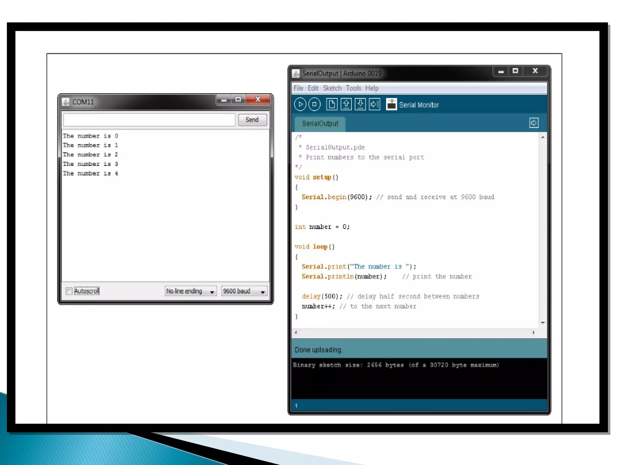
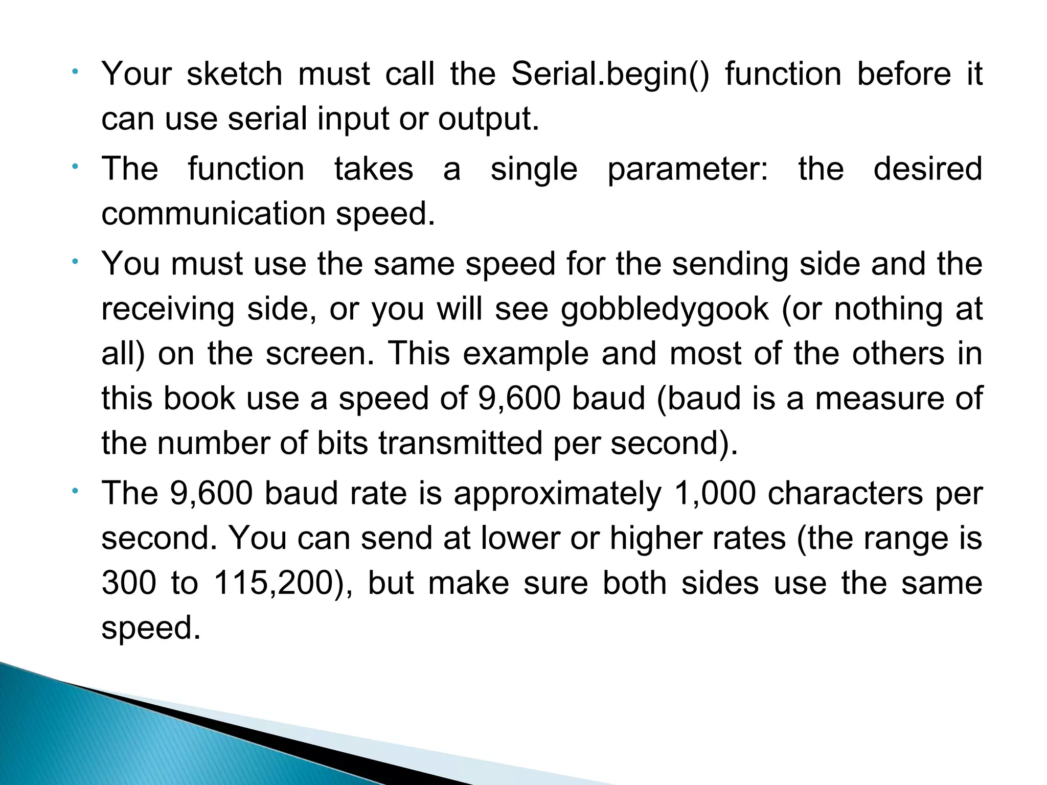
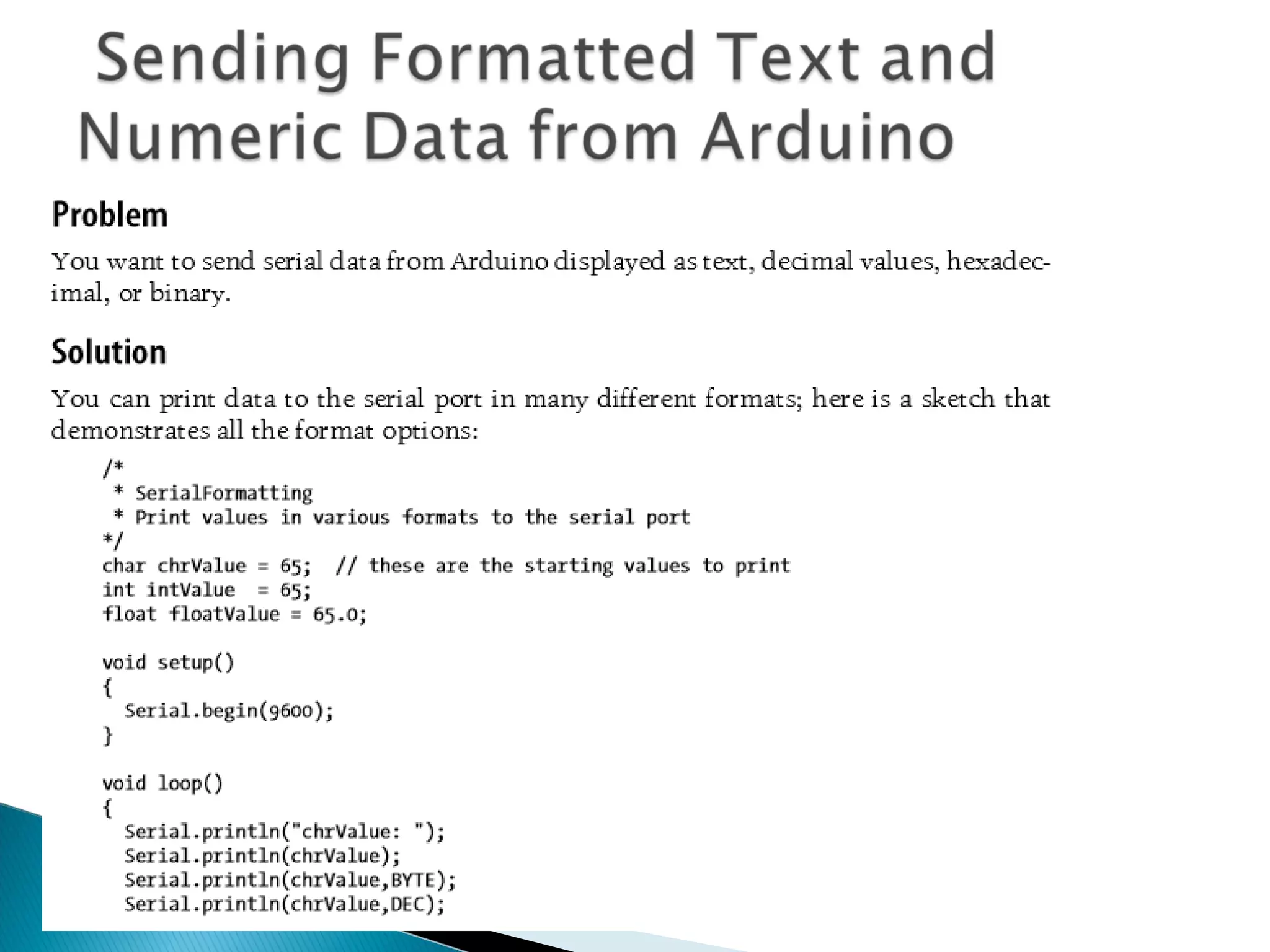
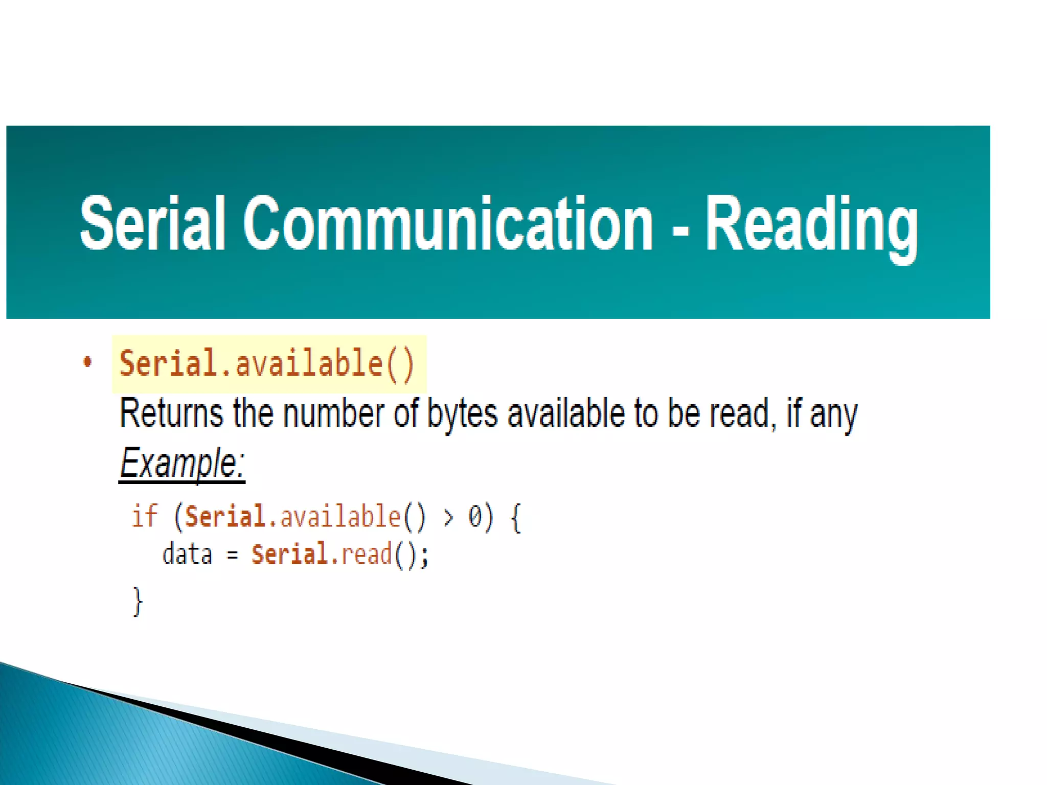
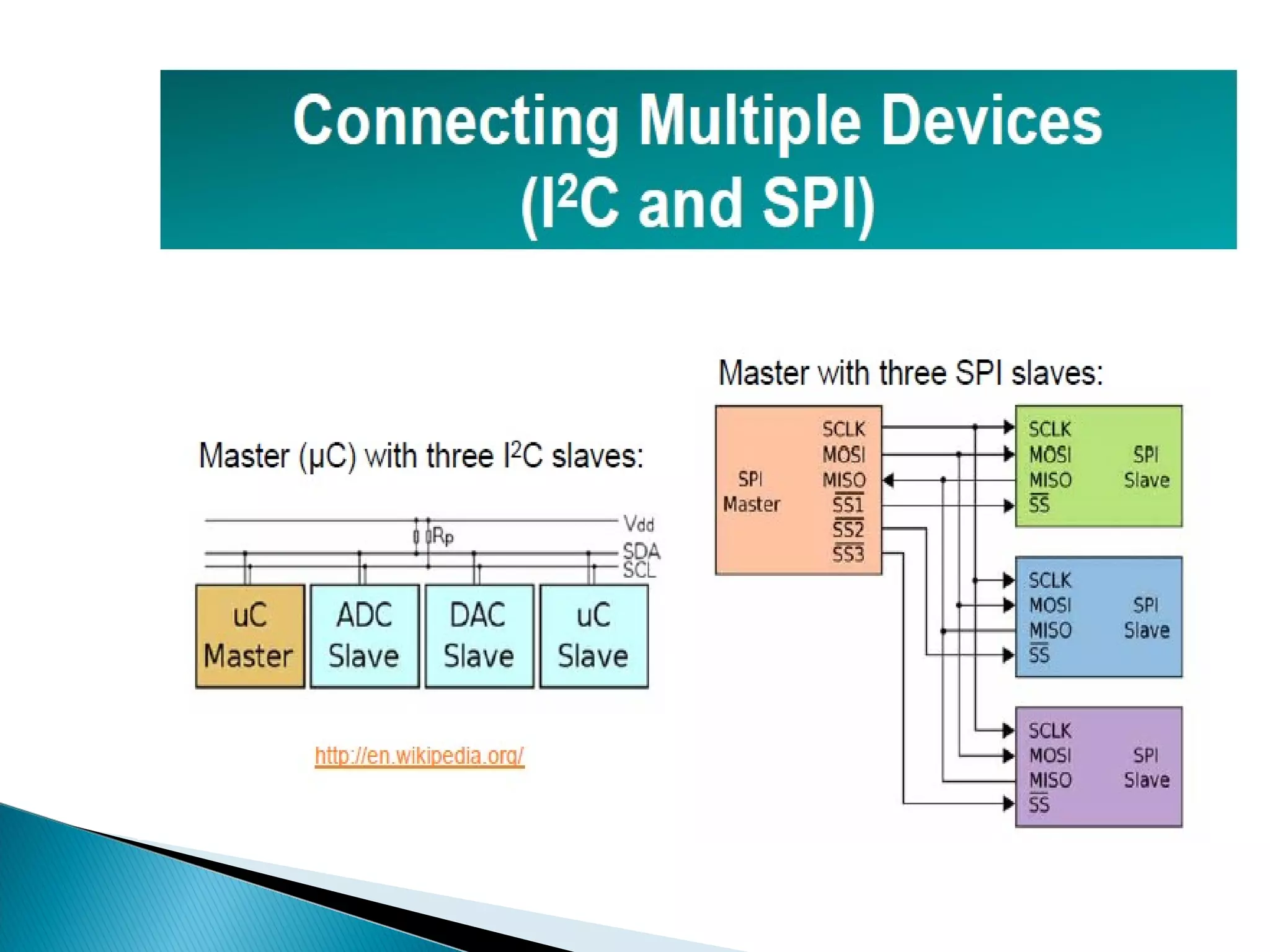
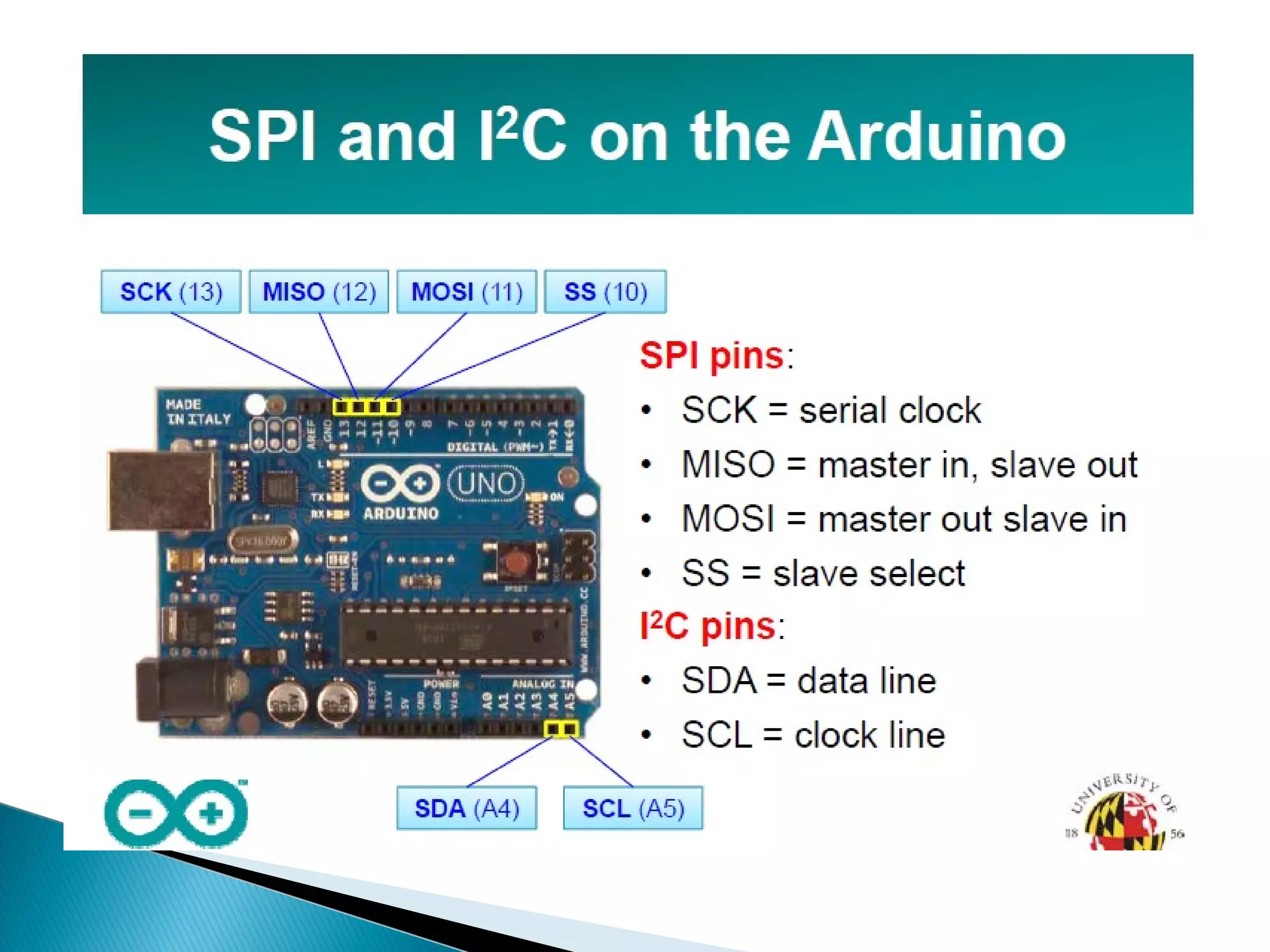
The document provides an overview of Arduino, detailing its architecture, pin configurations, and features of the Atmega 328 microcontroller. It describes serial communication methods for data exchange with computers and other devices, emphasizing the importance of matching baud rates for successful communication. Additionally, it covers I2C and SPI protocols, explaining the roles of master and slave devices in these communication systems.
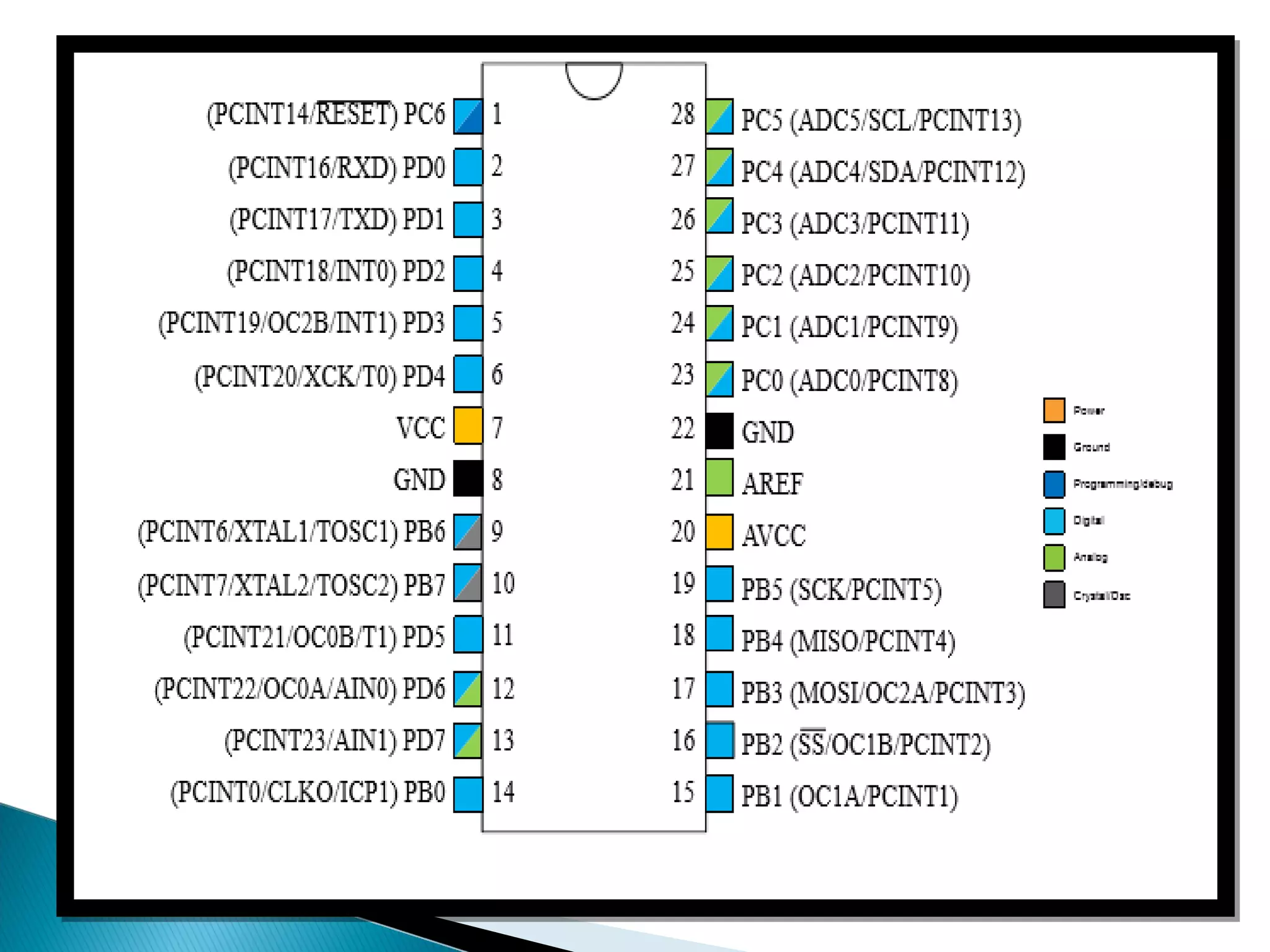
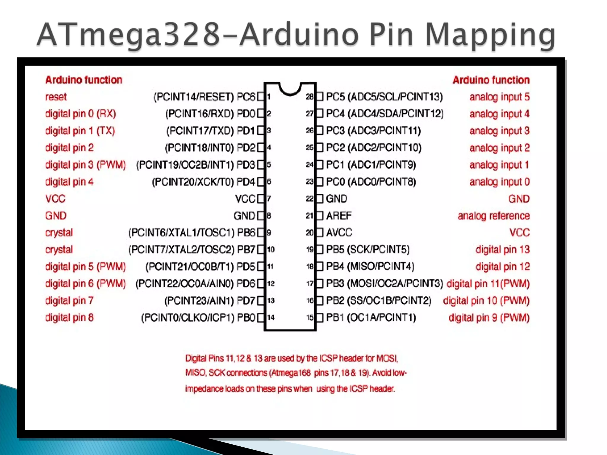
![ VCC Digital supply voltage. GND Ground. Port B (PB[7:0]) XTAL1/XTAL2/TOSC1/TOSC2 Port B is an 8-bit bi-directional I/O port with internal pull-up resistors (selected for each bit).](https://image.slidesharecdn.com/16509ece313unit41-180622120238/75/ARDUINO-AND-ITS-PIN-CONFIGURATION-10-2048.jpg)
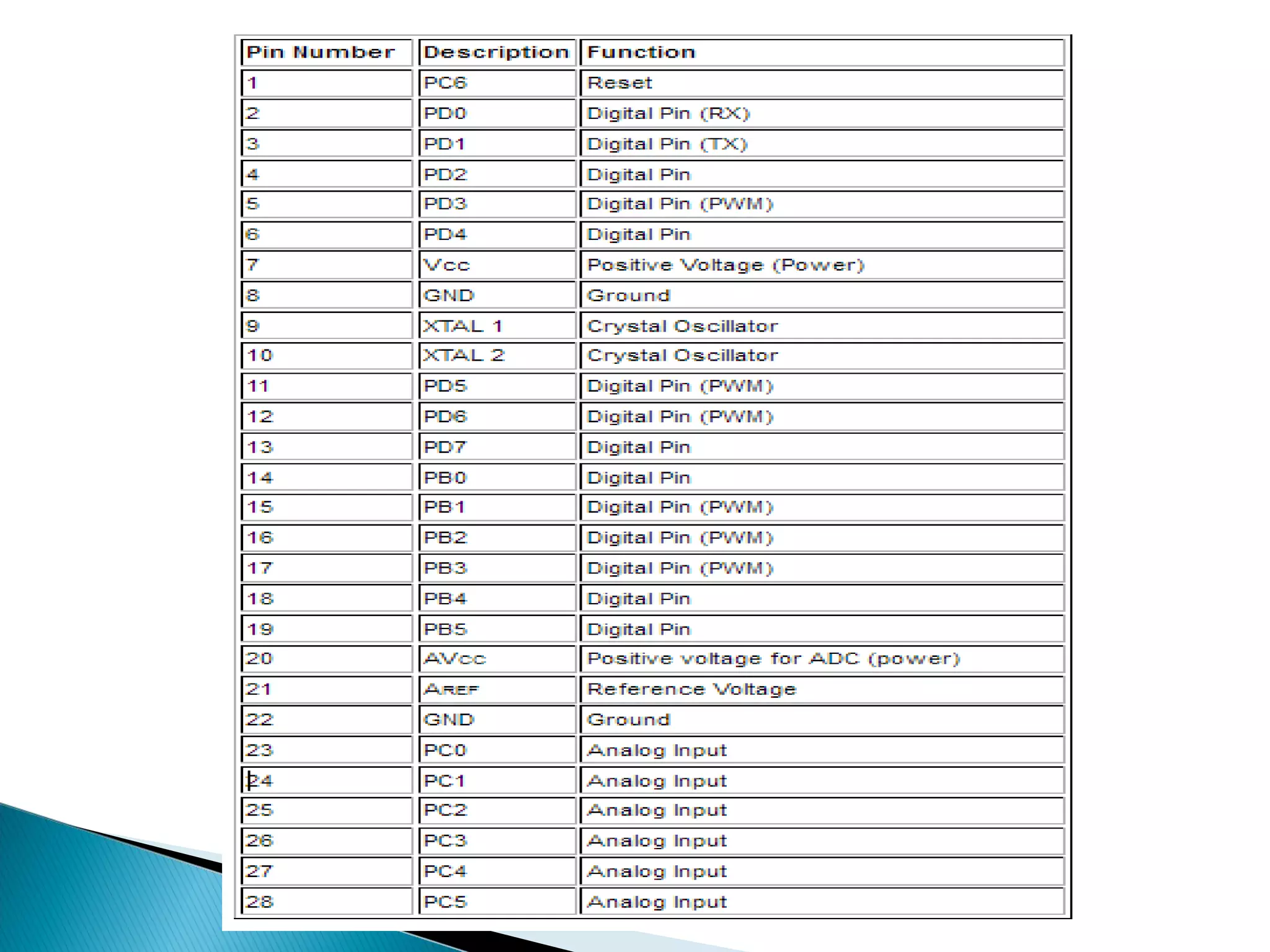
![PB[7:6] is used as TOSC[2:1] input for the Asynchronous Timer/Counter2 Port C (PC[5:0]) Port C is a 7-bit bi-directional I/O port with internal pull-up resistors (selected for each bit). PC6/RESET If the RSTDISBL Fuse is programmed, PC6 is used as an I/O pin. .Port D (PD[7:0]) Port D is an 8-bit bi-directional I/O port with internal pull-up resistors (selected for each bit). AVCC is the supply voltage pin for the A/D Converter AREF is the analog reference pin for the A/D Converter.](https://image.slidesharecdn.com/16509ece313unit41-180622120238/75/ARDUINO-AND-ITS-PIN-CONFIGURATION-11-2048.jpg)