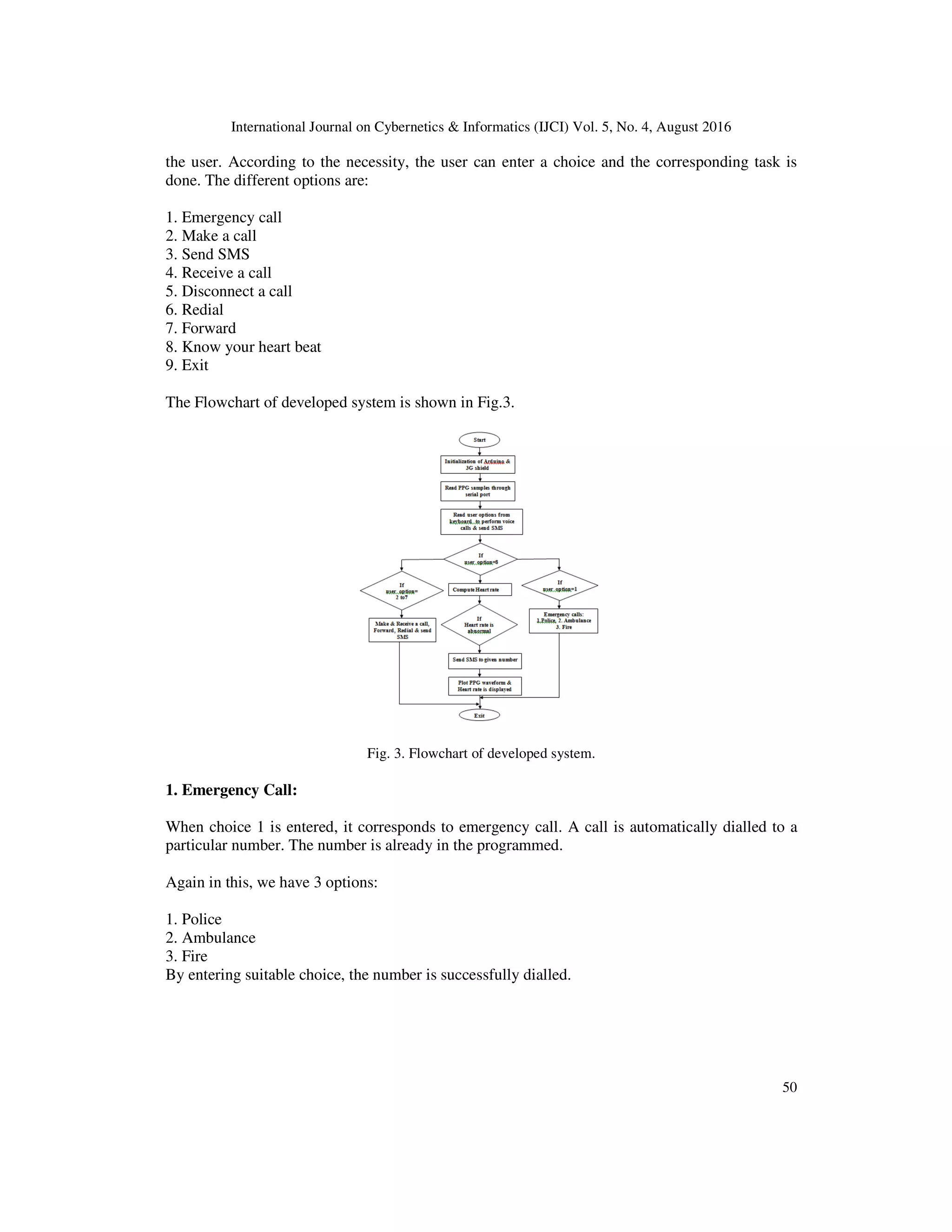
International Journal on Cybernetics & Informatics (IJCI) Vol. 5, No. 4, August 2016 DOI: 10.5121/ijci.2016.5406 47 ARDUINO BASED ABNORMAL HEART RATE DETECTION AND WIRELESS COMMUNICATION L.V.Rajani Kumari 1 , Y. Padma Sai 2 N. Balaji 3 1 Department of ECE, VNRVJIET, Hyderabad, India 2 Department of ECE, VNRVJIET, Hyderabad, India 3 Department of ECE, JNTUK, Vizianagaram, India ABSTRACT The heart rate is to be monitored continuously for the heart patients. This paper proposed a system that awakes to monitor the heart rate condition of the patient. This work includes two parts. 1) We developed an application to monitor the patient’s heart beat and if the heart beat is abnormal, a message should be transmitted to the doctor using 3G shield. Thus, doctors could monitor the patient’s heart rate condition continuously and suggests few earlier precautions to the patient. The heart rate is detected by using photoplethysmograph (PPG) technique. 2) The Arduino wireless communication is developed in such a way that it performs voice calls, sends SMS by interfacing with 3G shield using AT commands. One of the input given is a user specified number to be dial and the expected output is voice call should be successfully performed. Here the program is written in such a way that there are many options available like dynamic call, emergency call (police, ambulance, and fire), sending message, receiving call, Disconnect a call, Redial, Forward message. KEYWORDS PPG, 3G shield, Arduino, SMS, AT commands. 1. INTRODUCTION Now-a-days the development and usage of the mobile systems and wireless networks became prominent. There is an enhancement in telemedicine applications and patient monitoring. To improve cost reduction, resource management, time and patient care, the mobile systems and wireless networks[10-12] will be an aid in hospital and other medical environments. The real- time information is useful for making critical decisions about the care of the patients, the demands on strength and consistency of wireless communication systems[8] can be used by medical environment. Wireless networks can be used in hospitals in order to provide network infrastructure for clerical work but not for health monitoring systems. The Instruments that are used for monitoring health conditions are not networked and are not controlled or monitored remotely [1,11]. This paper on hand a system that is developed which is able to monitor and alert’s the doctors and/or patient’s relatives regarding the patient’s heartbeat conditions. Using processing software, a heart beat sensor circuit is designed which adopted photoplethysmograph (PPG) technique. The Signals that are detected are analyzed and processed before sent through SMS to family members and medical experts. It is advantageous in terms of cost, save time, no complicated settings, and even very useful for patient who lives alone. The developed system also perform a voice call, sending SMS using Arduino board and a 3G shield using AT commands.
International Journal on Cybernetics & Informatics (IJCI) Vol. 5, No. 4, August 2016 48 Input given to the project is user specified number to be dial and the expected output voice call should be successfully dialed. While forwarding the SMS the user specified number is dialed and the message to be sent is given and the required output is to send the message to that particular number successfully. There is a need for wireless transmission of heart rate information to handheld devices that are used by medical practitioners. PPG techniques have been adopted in the design by the authors in [5].For developing the monitoring of cardiovascular state of the patients, the researchers [5] presented their idea of a device . It is useful for monitoring the cardiovascular state of the patients. All recorded physiological signals (ECG, PPG photopletysmograph) are stored for medical post-processing. If in case of critical values of the measured parameters occurs, they also proposed that the doctors or relatives can be informed by an automatically sent SMS. Yet, no additional results on this research are disclosed. A practical system is developed for monitoring heartbeat which does not use the self–count pulsation of blood or ECG signal [6]. Using a 7-segment display, output of the sensor is viewed on the counter display through the numbers of beat count. For every two seconds, the reading is updated on the counter display.The main intention of system development in [7] is to build a heart rate monitor using the wireless transmission to the receiver which displays the heart rate [9] in beats per minute. The system uses the Bluetooth technology to communicate data with a terminal computer. The system’s drawback is the distance between sensor and the computer should not more than 20 meters which is impractical to be implemented. 2. PROPOSED SYSTEM The proposed system is to send the heart rate information to the doctor through SMS, if there are any abnormalities in heart rate of the patient, they will get patient’s information from their mobile, and then simply, they provide treatment within short time. This paper is based on development of Arduino wireless communication system and heart rate monitoring by sending SMS to monitor the cardiac patients. Fig. 1. Block diagram of Proposed System The Block diagram of proposed system is shown in Fig 1. The block diagram contains PPG sensor circuit, Arduino Uno,3G shield module and personal computer .When finger is placed into the sensor, the PPG signal is generated which is filtered and amplified. Arduino reads the PPG signal continuously and transmits the data to the PC through the USB-UART interface. On PC, we develop an algorithm that reads the incoming PPG signal from the Arduino and process them to find out the heart rate[2]. The Processing software is used to plot PPG signal. An alert message
International Journal on Cybernetics & Informatics (IJCI) Vol. 5, No. 4, August 2016 49 will be sent to mobile phone by 3G shield ,if there is any abnormal heart rate is detected. Then doctor will get the patient heart rate information by monitoring in his mobile. 2.1. Photoplethysmograph PPG is a low-cost and simple optical technique that can be used for detecting blood volume changes in the microvascular bed of the tissue. Recurrently, it is used noninvasively to obtain measurements at the skin surface [3]. By using the pulse oximeter, which illuminates the skin and measure the changes in the light absorption [4] ,a PPG is obtained. Typically, to determine blood flow the PPG tool uses an emitter receiver pair. It consists of a photodiode and matched infrared emitter, which transmits the changes in infrared reflectance resulting from varying blood flow. A photo detector and an IR LED are placed on two opposite sides and are made to face each other. When a fingertip is placed into the sensor, the IR light coming from the LED is illuminated on it[13] . The photo detector diode obtains the transmitted light through tissue on other side. Based on the tissue blood volume, more or less light is transmitted. Accordingly, the transmitted light intensity changes with pulsing of the blood with heart beat. A plot for this variation to time is referred as photoplethysmographic[7] or PPG signal. 2.2 ArduinoUno & 3 G shield The 3G module which is connected to Arduino allows downlinks rates over 115200 bauds (~11.5KBps). Fig.2. shows the interfacing of Arduino Uno & 3G shield. Fig. 2. Arduino interfaced with 3G shield. The first thing that we are going to do with the system is to connect the module to a PC directly (using an Arduino as gateway) and refer the basic AT commands. In this case, serial communication jumpers have to be set on USB gateway position. Then connect the SIM card and the USB cable. Finally plug the USB cable to the computer and open a serial port terminal to communicate via USB port (e.g: hyperterminal (win), cutecom / gtkterm (linux)).Set the baud rate to 115200 bps and open the serial port, then press the ON button for two seconds. Then, if we type AT we'll get OK, it means that the communication with the module is working fine. Now, with the module working you can check some AT commands to control the module. 3. RESULTS AND DISCUSSIONS Arduino wireless communication is established by using Sketch, generally programme written in arduino software is dumped into the Arduino board via USB serial communication and made to run.The output is displayed on the serial monitor. The programme displays 8 different options to
International Journal on Cybernetics & Informatics (IJCI) Vol. 5, No. 4, August 2016 50 the user. According to the necessity, the user can enter a choice and the corresponding task is done. The different options are: 1. Emergency call 2. Make a call 3. Send SMS 4. Receive a call 5. Disconnect a call 6. Redial 7. Forward 8. Know your heart beat 9. Exit The Flowchart of developed system is shown in Fig.3. Fig. 3. Flowchart of developed system. 1. Emergency Call: When choice 1 is entered, it corresponds to emergency call. A call is automatically dialled to a particular number. The number is already in the programmed. Again in this, we have 3 options: 1. Police 2. Ambulance 3. Fire By entering suitable choice, the number is successfully dialled.
International Journal on Cybernetics & Informatics (IJCI) Vol. 5, No. 4, August 2016 51 2. Make a Call: Here the number to which we are intended to call is to be dialled in the serial monitor. The present work has a facility of dialling calls of more than 10 digits (i.e., we can call to other countries even). 3. Send SMS: By entering choice 3, we choose the option of sending SMS. Here the number to which the message should be entered and also the message. 4. Receive a Call: We can receive the incoming calls by entering this choice provided that the speaker beeps. 5. Disconnect a Call: A call can be disconnected by entering this choice at any time. 6. Redial: A facility for the purpose of calling to the last dialled number is given. If you enter the choice 6 for your first call, automatically message is displayed. 7. Forwarding the last message: The last sent message is forwarded by entering this choice. If you enter choice 7 and it is your first message, then message is displayed on the serial monitor. 8. Know your heart beat: Place the finger in the holder and get the heart beat. Run the processing software to show the PPG Waveform 9. Exit: This option makes to exit out of the programme. Fig.4. shows the Arduino programming and serial window for selecting the option by the user. Fig.4. Complete setup of the proposed system
International Journal on Cybernetics & Informatics (IJCI) Vol. 5, No. 4, August 2016 52 A basic circuit to display the PPG waveform, detect the abnormalities in it and emergency calling if it senses the abnormalities is built using Arduino. In this application heart rate is calculated using PPG sensor and Arduino uno. Fig. 5. Developed system with PPG waveform. Fig.5. shows the continuously varying PPG waveform. Based on the number of heart beats per minute message will be sent to doctor. Message is sent by interfacing Arduino Uno with 3G shield. If the heart rate is abnormal, message will be automatically sent to the doctor. Fig.6. shows the heart rate display on the serial window. Fig.6. Developed system with heart rate. CONCLUSIONS This paper presents a development in Arduino wireless communication and heart rate monitoring system based on SMS for biomedical applications. This system is developed by integration of both hardware and software components. The developed system is to perform voice calls, send SMS by interfacing with 3G shield using AT commands. One of the input given is a user specified number to be dial and the expected output is voice call should be successfully performed. We developed an application to monitor the patient heart beat and if the heart beat is abnormal, a message should be transmitted to the doctor using 3G shield.
International Journal on Cybernetics & Informatics (IJCI) Vol. 5, No. 4, August 2016 53 REFERENCES [1] Matthew D’Souza, Montserrat Ros, Adam Postula.,”Wireless Medical Information System for Patient ECG Monitoring” IEEE, 2013. [2] D. Parekh, “Designing Heart Rate, Blood Pressure and Body Temperature Sensors for Mobile On- Call System,” EE 4BI6 Electrical Engineering Biomedical Capstones, Department of Electrical and Computer Engineering, McMaster University, 2010 [3] Allen J. “Photoplethysmography and its application in clinical physiological measurement”, Physiol Meas. 2007 Mar; 28(3):R1-39. Epub 2007 [4] Shelley, K. H., R. G. Stout, et al. "The Use of Joint Time Frequency Analysis of The Pulse Oximeter Waveform to Measure The Respiratory Rate of Ventilated Patients." Anesthesiology 91(3A): A583,1999. [5] Péter Csordàs, Balázs Scherer (2006), “Development and Applications of A Home Health Monitoring Device”, Proc. of International Carpathian Control Conference ICCC’ 2006. [6] L.V.Rajani kumari,Y.Padma sai,N.Balaji,M.Tejaswi kumar,”ECG Monitoring System Using ARM9 Web-Server”in Proc. IEEE Global conference on communication Technologies,2015(In press) [7] Jeong, In Cheol et al. “A new method to estimate arterial blood pressure Using Photoplethysmographic signal”, Conf. Proc. IEEE Eng Med Biol Soc 1:4667-70,2006 8] Patrick O. Bobbie,Chaudary Zeeshan Arif, Hema Chaudhari, Sagar Pujari,”Electrocardiogram (EKG) Data Acquisition and Wireless Transmission”, IEEE Transactions on Information Technology in Biomedicine, vol. 7, pp. 101-107, 2011. [9] Md. Maruf Hussain Shuvo,Krishna Chandra Roy,Md.Rokibul hasan Robin “Development of a portable GSM SMS-based patient monitoring system for health care applicatios”,Global Journal of computer science & TechnologyVol-14,2014. [10] S.Saravanan, “Remote Patient Monitoring in Telemedicine using computer communication network through Bluetooth, Wi- Fi, Internet Android Mobile”, International journal of advanced research in computer and computer Engineering ,July-2014. [11] P.Vignesh, “Implementation of ECG signal Acquisition and transmission through Bluetooth Technology, ” in Proc. IEEE Int.Workshop,Mumbai October-2014. [12] Bernardo Goncalves,Jose G. Pereria Filho, Rodrigo V.Andreao, Giancarlo Guizzardi,”ECG data provisioning for Telehomecare Monitoring”,2008 ACM 978-1-595953/753. [13] Warsuzarina Mat Jubadi, Siti Faridatul Aisyah Mohd Sahak,” Heartbeat Monitoring Alert via SMS”, IEEE Symposium on Industrial Electronics and Applications (ISIEA 2009), October 4-6, 2009 [14] Ketaki N. Patil, P.C.Bhaskar,”Transmission of ARM based Real time ECG for monitoring remotely located Patient”, International Journal of Research in Engineering and Technology. July-2013. [15] C. De Capua, A. Meduri, and R. Morello, “A remote doctor for Homecare and medical diagnoses on cardiac patients by an Adaptive ECG analysis”,inProc. IEEE 4th Int. Workshop Med. Meas. Appl., Cetraro, Italy, May 29–30, 2009, pp. 31–36.

Arduino Based Abnormal Heart Rate Detection and Wireless Communication

  • 1.
    International Journal onCybernetics & Informatics (IJCI) Vol. 5, No. 4, August 2016 DOI: 10.5121/ijci.2016.5406 47 ARDUINO BASED ABNORMAL HEART RATE DETECTION AND WIRELESS COMMUNICATION L.V.Rajani Kumari 1 , Y. Padma Sai 2 N. Balaji 3 1 Department of ECE, VNRVJIET, Hyderabad, India 2 Department of ECE, VNRVJIET, Hyderabad, India 3 Department of ECE, JNTUK, Vizianagaram, India ABSTRACT The heart rate is to be monitored continuously for the heart patients. This paper proposed a system that awakes to monitor the heart rate condition of the patient. This work includes two parts. 1) We developed an application to monitor the patient’s heart beat and if the heart beat is abnormal, a message should be transmitted to the doctor using 3G shield. Thus, doctors could monitor the patient’s heart rate condition continuously and suggests few earlier precautions to the patient. The heart rate is detected by using photoplethysmograph (PPG) technique. 2) The Arduino wireless communication is developed in such a way that it performs voice calls, sends SMS by interfacing with 3G shield using AT commands. One of the input given is a user specified number to be dial and the expected output is voice call should be successfully performed. Here the program is written in such a way that there are many options available like dynamic call, emergency call (police, ambulance, and fire), sending message, receiving call, Disconnect a call, Redial, Forward message. KEYWORDS PPG, 3G shield, Arduino, SMS, AT commands. 1. INTRODUCTION Now-a-days the development and usage of the mobile systems and wireless networks became prominent. There is an enhancement in telemedicine applications and patient monitoring. To improve cost reduction, resource management, time and patient care, the mobile systems and wireless networks[10-12] will be an aid in hospital and other medical environments. The real- time information is useful for making critical decisions about the care of the patients, the demands on strength and consistency of wireless communication systems[8] can be used by medical environment. Wireless networks can be used in hospitals in order to provide network infrastructure for clerical work but not for health monitoring systems. The Instruments that are used for monitoring health conditions are not networked and are not controlled or monitored remotely [1,11]. This paper on hand a system that is developed which is able to monitor and alert’s the doctors and/or patient’s relatives regarding the patient’s heartbeat conditions. Using processing software, a heart beat sensor circuit is designed which adopted photoplethysmograph (PPG) technique. The Signals that are detected are analyzed and processed before sent through SMS to family members and medical experts. It is advantageous in terms of cost, save time, no complicated settings, and even very useful for patient who lives alone. The developed system also perform a voice call, sending SMS using Arduino board and a 3G shield using AT commands.
  • 2.
    International Journal onCybernetics & Informatics (IJCI) Vol. 5, No. 4, August 2016 48 Input given to the project is user specified number to be dial and the expected output voice call should be successfully dialed. While forwarding the SMS the user specified number is dialed and the message to be sent is given and the required output is to send the message to that particular number successfully. There is a need for wireless transmission of heart rate information to handheld devices that are used by medical practitioners. PPG techniques have been adopted in the design by the authors in [5].For developing the monitoring of cardiovascular state of the patients, the researchers [5] presented their idea of a device . It is useful for monitoring the cardiovascular state of the patients. All recorded physiological signals (ECG, PPG photopletysmograph) are stored for medical post-processing. If in case of critical values of the measured parameters occurs, they also proposed that the doctors or relatives can be informed by an automatically sent SMS. Yet, no additional results on this research are disclosed. A practical system is developed for monitoring heartbeat which does not use the self–count pulsation of blood or ECG signal [6]. Using a 7-segment display, output of the sensor is viewed on the counter display through the numbers of beat count. For every two seconds, the reading is updated on the counter display.The main intention of system development in [7] is to build a heart rate monitor using the wireless transmission to the receiver which displays the heart rate [9] in beats per minute. The system uses the Bluetooth technology to communicate data with a terminal computer. The system’s drawback is the distance between sensor and the computer should not more than 20 meters which is impractical to be implemented. 2. PROPOSED SYSTEM The proposed system is to send the heart rate information to the doctor through SMS, if there are any abnormalities in heart rate of the patient, they will get patient’s information from their mobile, and then simply, they provide treatment within short time. This paper is based on development of Arduino wireless communication system and heart rate monitoring by sending SMS to monitor the cardiac patients. Fig. 1. Block diagram of Proposed System The Block diagram of proposed system is shown in Fig 1. The block diagram contains PPG sensor circuit, Arduino Uno,3G shield module and personal computer .When finger is placed into the sensor, the PPG signal is generated which is filtered and amplified. Arduino reads the PPG signal continuously and transmits the data to the PC through the USB-UART interface. On PC, we develop an algorithm that reads the incoming PPG signal from the Arduino and process them to find out the heart rate[2]. The Processing software is used to plot PPG signal. An alert message
  • 3.
    International Journal onCybernetics & Informatics (IJCI) Vol. 5, No. 4, August 2016 49 will be sent to mobile phone by 3G shield ,if there is any abnormal heart rate is detected. Then doctor will get the patient heart rate information by monitoring in his mobile. 2.1. Photoplethysmograph PPG is a low-cost and simple optical technique that can be used for detecting blood volume changes in the microvascular bed of the tissue. Recurrently, it is used noninvasively to obtain measurements at the skin surface [3]. By using the pulse oximeter, which illuminates the skin and measure the changes in the light absorption [4] ,a PPG is obtained. Typically, to determine blood flow the PPG tool uses an emitter receiver pair. It consists of a photodiode and matched infrared emitter, which transmits the changes in infrared reflectance resulting from varying blood flow. A photo detector and an IR LED are placed on two opposite sides and are made to face each other. When a fingertip is placed into the sensor, the IR light coming from the LED is illuminated on it[13] . The photo detector diode obtains the transmitted light through tissue on other side. Based on the tissue blood volume, more or less light is transmitted. Accordingly, the transmitted light intensity changes with pulsing of the blood with heart beat. A plot for this variation to time is referred as photoplethysmographic[7] or PPG signal. 2.2 ArduinoUno & 3 G shield The 3G module which is connected to Arduino allows downlinks rates over 115200 bauds (~11.5KBps). Fig.2. shows the interfacing of Arduino Uno & 3G shield. Fig. 2. Arduino interfaced with 3G shield. The first thing that we are going to do with the system is to connect the module to a PC directly (using an Arduino as gateway) and refer the basic AT commands. In this case, serial communication jumpers have to be set on USB gateway position. Then connect the SIM card and the USB cable. Finally plug the USB cable to the computer and open a serial port terminal to communicate via USB port (e.g: hyperterminal (win), cutecom / gtkterm (linux)).Set the baud rate to 115200 bps and open the serial port, then press the ON button for two seconds. Then, if we type AT we'll get OK, it means that the communication with the module is working fine. Now, with the module working you can check some AT commands to control the module. 3. RESULTS AND DISCUSSIONS Arduino wireless communication is established by using Sketch, generally programme written in arduino software is dumped into the Arduino board via USB serial communication and made to run.The output is displayed on the serial monitor. The programme displays 8 different options to
  • 4.
    International Journal onCybernetics & Informatics (IJCI) Vol. 5, No. 4, August 2016 50 the user. According to the necessity, the user can enter a choice and the corresponding task is done. The different options are: 1. Emergency call 2. Make a call 3. Send SMS 4. Receive a call 5. Disconnect a call 6. Redial 7. Forward 8. Know your heart beat 9. Exit The Flowchart of developed system is shown in Fig.3. Fig. 3. Flowchart of developed system. 1. Emergency Call: When choice 1 is entered, it corresponds to emergency call. A call is automatically dialled to a particular number. The number is already in the programmed. Again in this, we have 3 options: 1. Police 2. Ambulance 3. Fire By entering suitable choice, the number is successfully dialled.
  • 5.
    International Journal onCybernetics & Informatics (IJCI) Vol. 5, No. 4, August 2016 51 2. Make a Call: Here the number to which we are intended to call is to be dialled in the serial monitor. The present work has a facility of dialling calls of more than 10 digits (i.e., we can call to other countries even). 3. Send SMS: By entering choice 3, we choose the option of sending SMS. Here the number to which the message should be entered and also the message. 4. Receive a Call: We can receive the incoming calls by entering this choice provided that the speaker beeps. 5. Disconnect a Call: A call can be disconnected by entering this choice at any time. 6. Redial: A facility for the purpose of calling to the last dialled number is given. If you enter the choice 6 for your first call, automatically message is displayed. 7. Forwarding the last message: The last sent message is forwarded by entering this choice. If you enter choice 7 and it is your first message, then message is displayed on the serial monitor. 8. Know your heart beat: Place the finger in the holder and get the heart beat. Run the processing software to show the PPG Waveform 9. Exit: This option makes to exit out of the programme. Fig.4. shows the Arduino programming and serial window for selecting the option by the user. Fig.4. Complete setup of the proposed system
  • 6.
    International Journal onCybernetics & Informatics (IJCI) Vol. 5, No. 4, August 2016 52 A basic circuit to display the PPG waveform, detect the abnormalities in it and emergency calling if it senses the abnormalities is built using Arduino. In this application heart rate is calculated using PPG sensor and Arduino uno. Fig. 5. Developed system with PPG waveform. Fig.5. shows the continuously varying PPG waveform. Based on the number of heart beats per minute message will be sent to doctor. Message is sent by interfacing Arduino Uno with 3G shield. If the heart rate is abnormal, message will be automatically sent to the doctor. Fig.6. shows the heart rate display on the serial window. Fig.6. Developed system with heart rate. CONCLUSIONS This paper presents a development in Arduino wireless communication and heart rate monitoring system based on SMS for biomedical applications. This system is developed by integration of both hardware and software components. The developed system is to perform voice calls, send SMS by interfacing with 3G shield using AT commands. One of the input given is a user specified number to be dial and the expected output is voice call should be successfully performed. We developed an application to monitor the patient heart beat and if the heart beat is abnormal, a message should be transmitted to the doctor using 3G shield.
  • 7.
    International Journal onCybernetics & Informatics (IJCI) Vol. 5, No. 4, August 2016 53 REFERENCES [1] Matthew D’Souza, Montserrat Ros, Adam Postula.,”Wireless Medical Information System for Patient ECG Monitoring” IEEE, 2013. [2] D. Parekh, “Designing Heart Rate, Blood Pressure and Body Temperature Sensors for Mobile On- Call System,” EE 4BI6 Electrical Engineering Biomedical Capstones, Department of Electrical and Computer Engineering, McMaster University, 2010 [3] Allen J. “Photoplethysmography and its application in clinical physiological measurement”, Physiol Meas. 2007 Mar; 28(3):R1-39. Epub 2007 [4] Shelley, K. H., R. G. Stout, et al. "The Use of Joint Time Frequency Analysis of The Pulse Oximeter Waveform to Measure The Respiratory Rate of Ventilated Patients." Anesthesiology 91(3A): A583,1999. [5] Péter Csordàs, Balázs Scherer (2006), “Development and Applications of A Home Health Monitoring Device”, Proc. of International Carpathian Control Conference ICCC’ 2006. [6] L.V.Rajani kumari,Y.Padma sai,N.Balaji,M.Tejaswi kumar,”ECG Monitoring System Using ARM9 Web-Server”in Proc. IEEE Global conference on communication Technologies,2015(In press) [7] Jeong, In Cheol et al. “A new method to estimate arterial blood pressure Using Photoplethysmographic signal”, Conf. Proc. IEEE Eng Med Biol Soc 1:4667-70,2006 8] Patrick O. Bobbie,Chaudary Zeeshan Arif, Hema Chaudhari, Sagar Pujari,”Electrocardiogram (EKG) Data Acquisition and Wireless Transmission”, IEEE Transactions on Information Technology in Biomedicine, vol. 7, pp. 101-107, 2011. [9] Md. Maruf Hussain Shuvo,Krishna Chandra Roy,Md.Rokibul hasan Robin “Development of a portable GSM SMS-based patient monitoring system for health care applicatios”,Global Journal of computer science & TechnologyVol-14,2014. [10] S.Saravanan, “Remote Patient Monitoring in Telemedicine using computer communication network through Bluetooth, Wi- Fi, Internet Android Mobile”, International journal of advanced research in computer and computer Engineering ,July-2014. [11] P.Vignesh, “Implementation of ECG signal Acquisition and transmission through Bluetooth Technology, ” in Proc. IEEE Int.Workshop,Mumbai October-2014. [12] Bernardo Goncalves,Jose G. Pereria Filho, Rodrigo V.Andreao, Giancarlo Guizzardi,”ECG data provisioning for Telehomecare Monitoring”,2008 ACM 978-1-595953/753. [13] Warsuzarina Mat Jubadi, Siti Faridatul Aisyah Mohd Sahak,” Heartbeat Monitoring Alert via SMS”, IEEE Symposium on Industrial Electronics and Applications (ISIEA 2009), October 4-6, 2009 [14] Ketaki N. Patil, P.C.Bhaskar,”Transmission of ARM based Real time ECG for monitoring remotely located Patient”, International Journal of Research in Engineering and Technology. July-2013. [15] C. De Capua, A. Meduri, and R. Morello, “A remote doctor for Homecare and medical diagnoses on cardiac patients by an Adaptive ECG analysis”,inProc. IEEE 4th Int. Workshop Med. Meas. Appl., Cetraro, Italy, May 29–30, 2009, pp. 31–36.