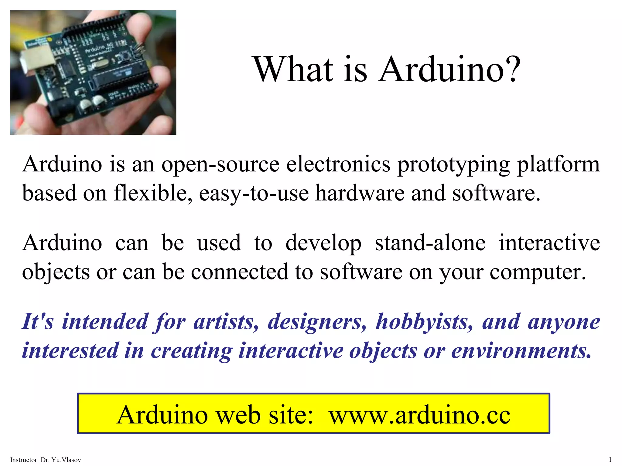
Arduino is an open-source electronics prototyping platform intended for artists, designers, hobbyists, and anyone interested in creating interactive objects or environments. It can be used to develop stand-alone interactive objects or can be connected to software on a computer. Arduino boards can be extended using shields that add specific features and can be programmed using the Arduino IDE software to read sensors and control motors or other devices.


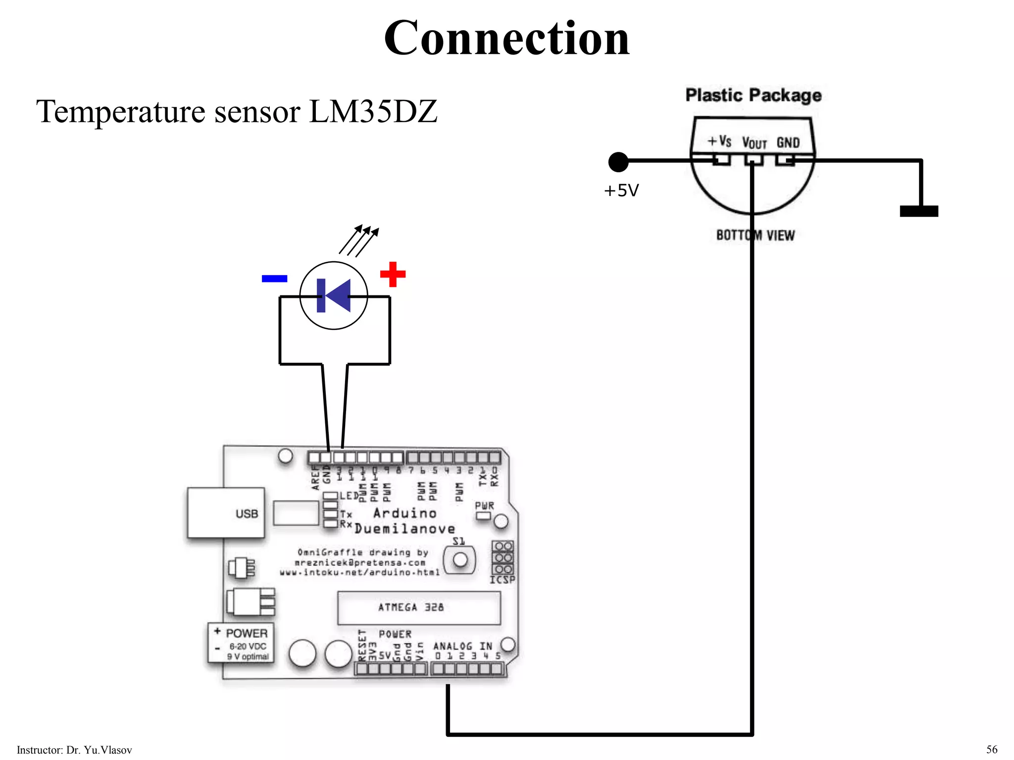
![// LM35DZ Temperature Sensor for Arduino. // (cc) by Daniel Spillere Andrade , http://www.danielandrade.net int pin = 0; // analog input pin int tempc = 0,tempf=0; // temperature variables int samples[8]; // variables to make a better precision int maxi = -100,mini = 100; // to start max/min temperature int i; void setup() { Serial.begin(9600); // start serial communication } void loop() { for(i = 0; i<=7; i++) { // gets 8 samples of temperature samples[i] = ( 5.0 * analogRead(pin) * 100.0) / 1024.0; tempc = tempc + samples[i]; delay(10); } tempc = tempc/8; // better precision tempf = (tempc * 9)/ 5 + 32; // converts to fahrenheit if(tempc > maxi) {maxi = tempc;} // set max temperature if(tempc < mini) {mini = tempc;} // set min temperature Serial.print(tempc,DEC); Serial.print(" Celsius, "); Serial.print(tempf,DEC); Serial.print(" fahrenheit -> "); Serial.print(maxi,DEC); Serial.print(" Max, "); Serial.print(mini,DEC); Serial.println(" Min"); tempc = 0; delay(1000); // delay before loop } Example 09 LM35DZ temperature sensor 57 Instructor: Dr. Yu.Vlasov](https://image.slidesharecdn.com/arduinocode-221008100102-f056eaf6/75/Arduino_Code-ppt-57-2048.jpg)