The document outlines the design and development of an automatic irrigation system using the DS1307 timer sensor and Arduino Mega 2560, allowing control over devices like lights and motors based on set timings. It details the hardware components needed, including various relays and power supplies, along with their specifications, and provides an overview of the Arduino IDE for programming the system. Additionally, it includes circuit connection schematics for operating a lamp and an AC motor with specific on/off timings.
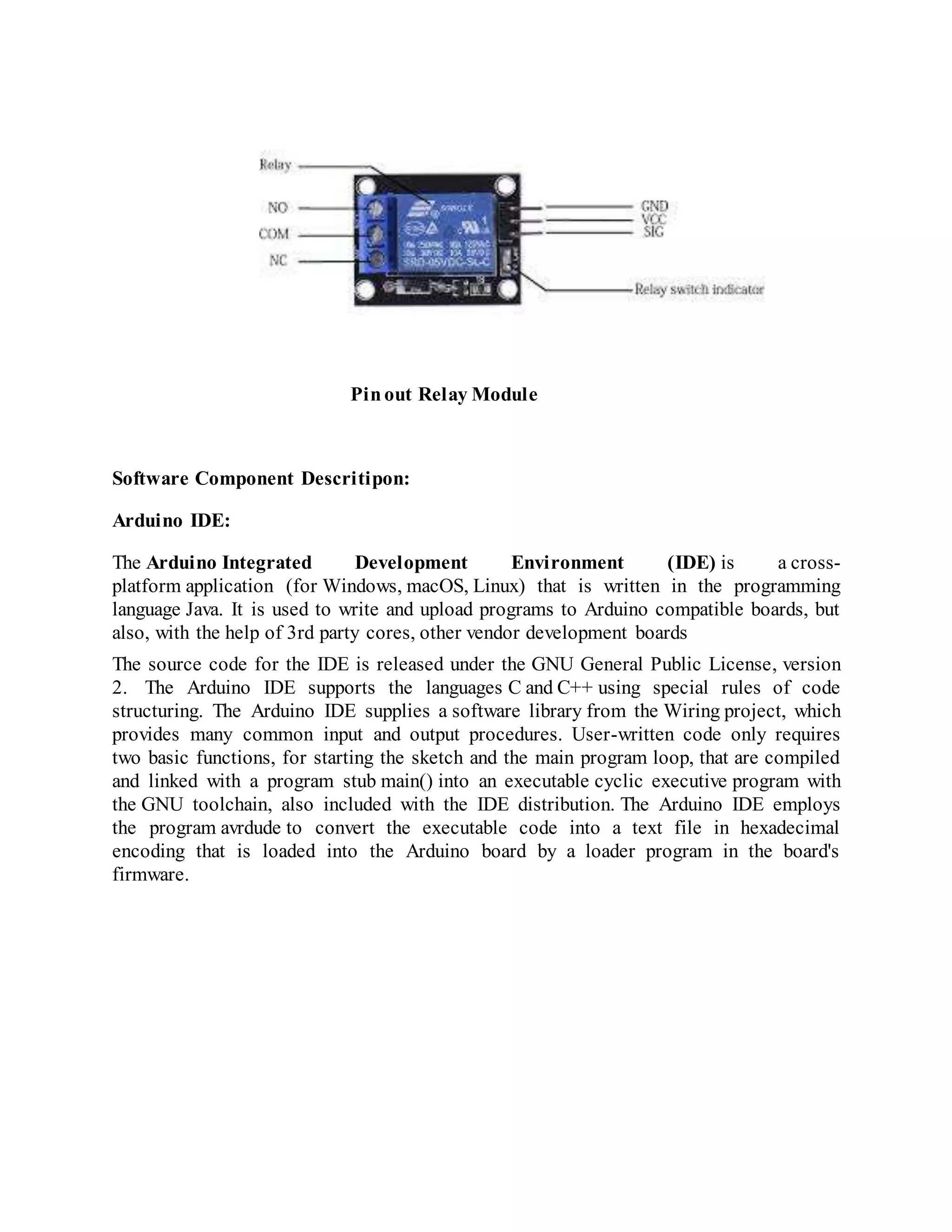
![The features of 1-Channel Relay module: Good for safe control of higher amperage circuits. In power systems, the lower current can control the higher one. Standard interface that can be controlled directly by microcontroller (Arduino , 8051, AVR, PIC, DSP, ARM)] Wide range of controllable voltages. Being able to control high load current, which can reach 250V, 10A or 125V, 15A With a normally-open (NO) contact and a normally-closed (NC) contact. Around the board with 4 mounting holes, easy installation and fixing It has a common end, a beginning, a closed-end Specificationof 1-Channel Relay module: Voltage to operate: 5V D Color : Blue Relays on a black PCB Load : 10A, AC 250V/ 15A, 125V](https://image.slidesharecdn.com/designanddevelopmentofautomaticirrigationsystemusingds1307timersensor-191117164910/75/Automatic-irrigation-system-using-Arduino-10-2048.jpg)