Download to read offline
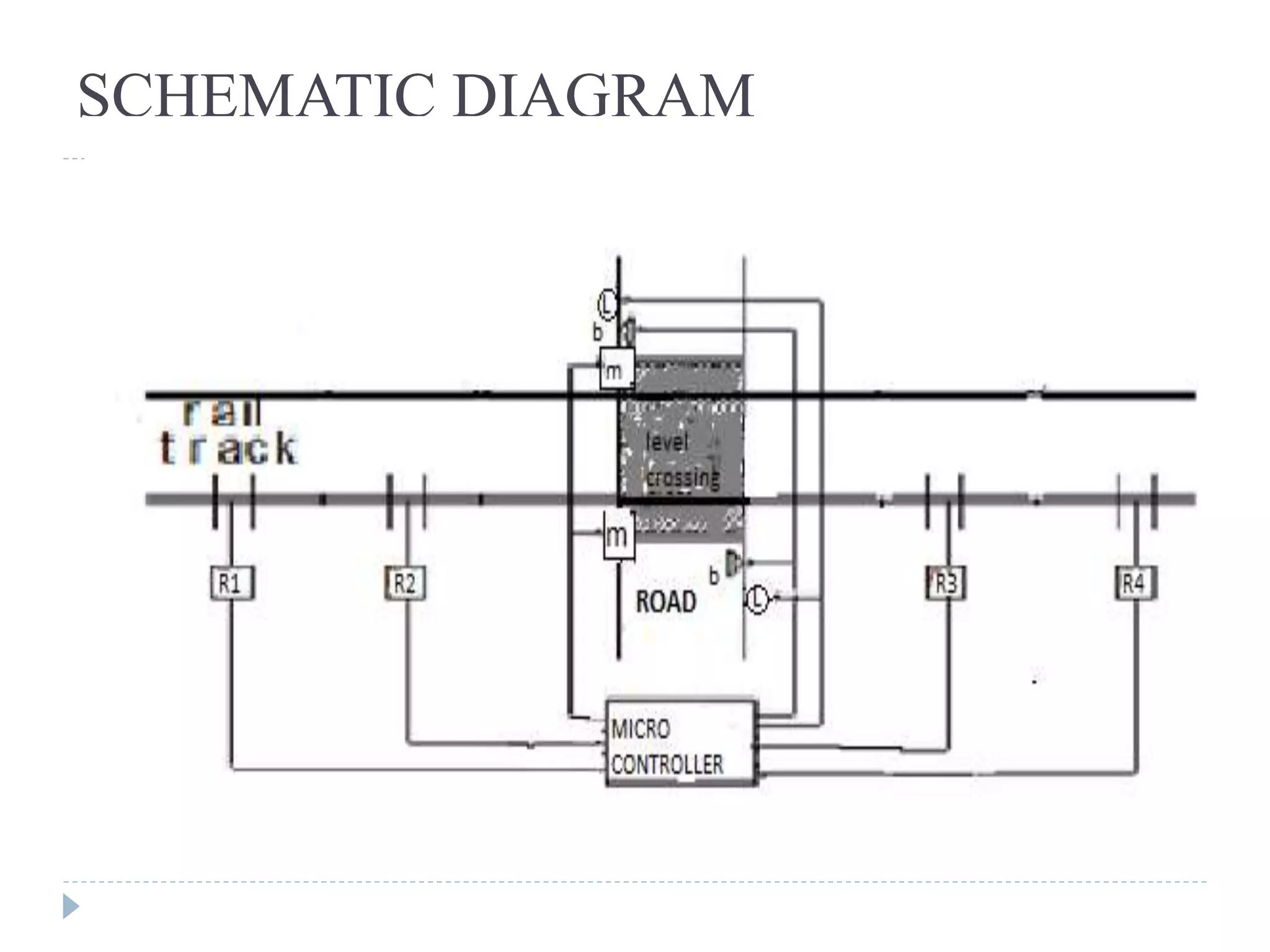

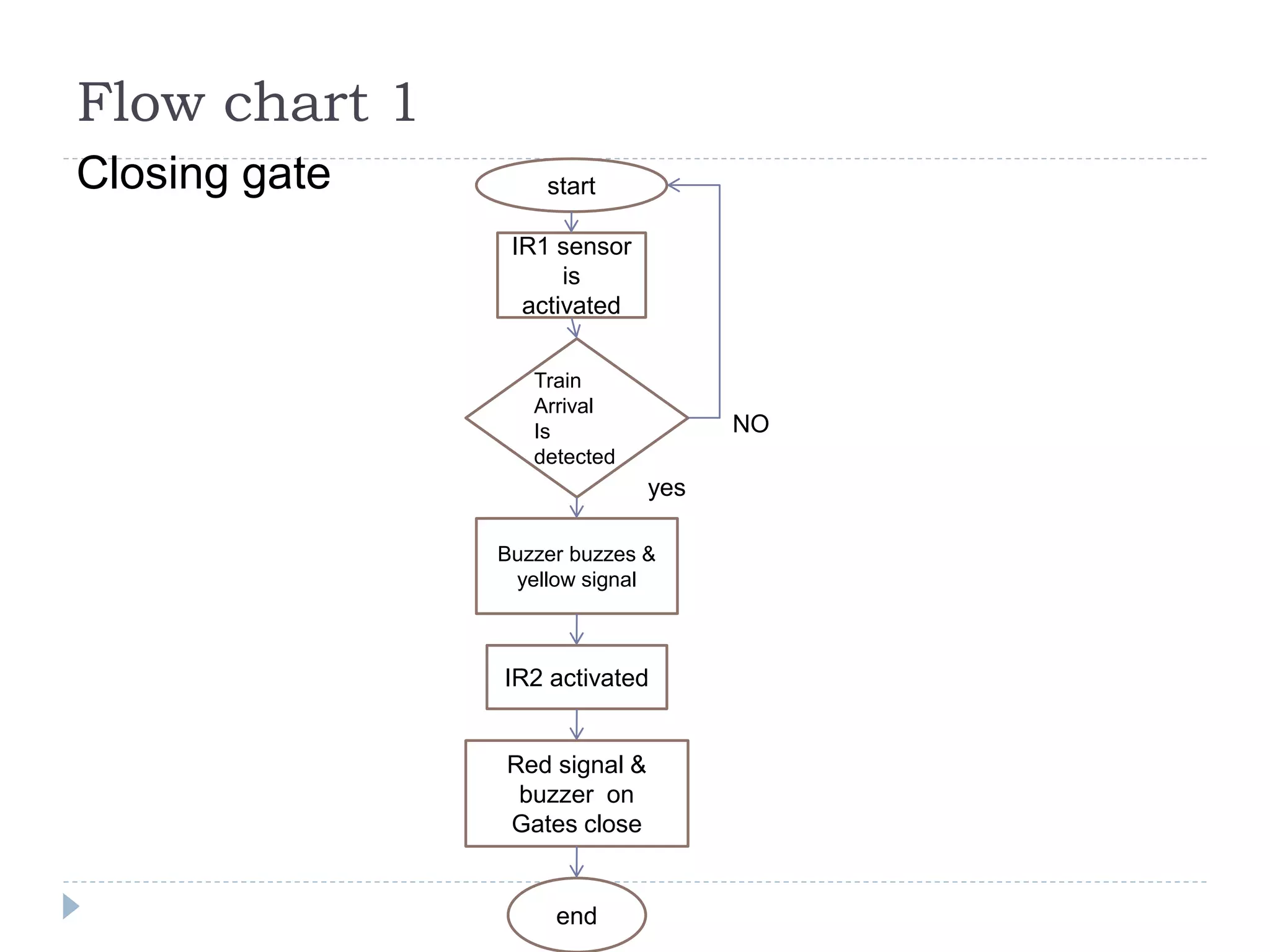
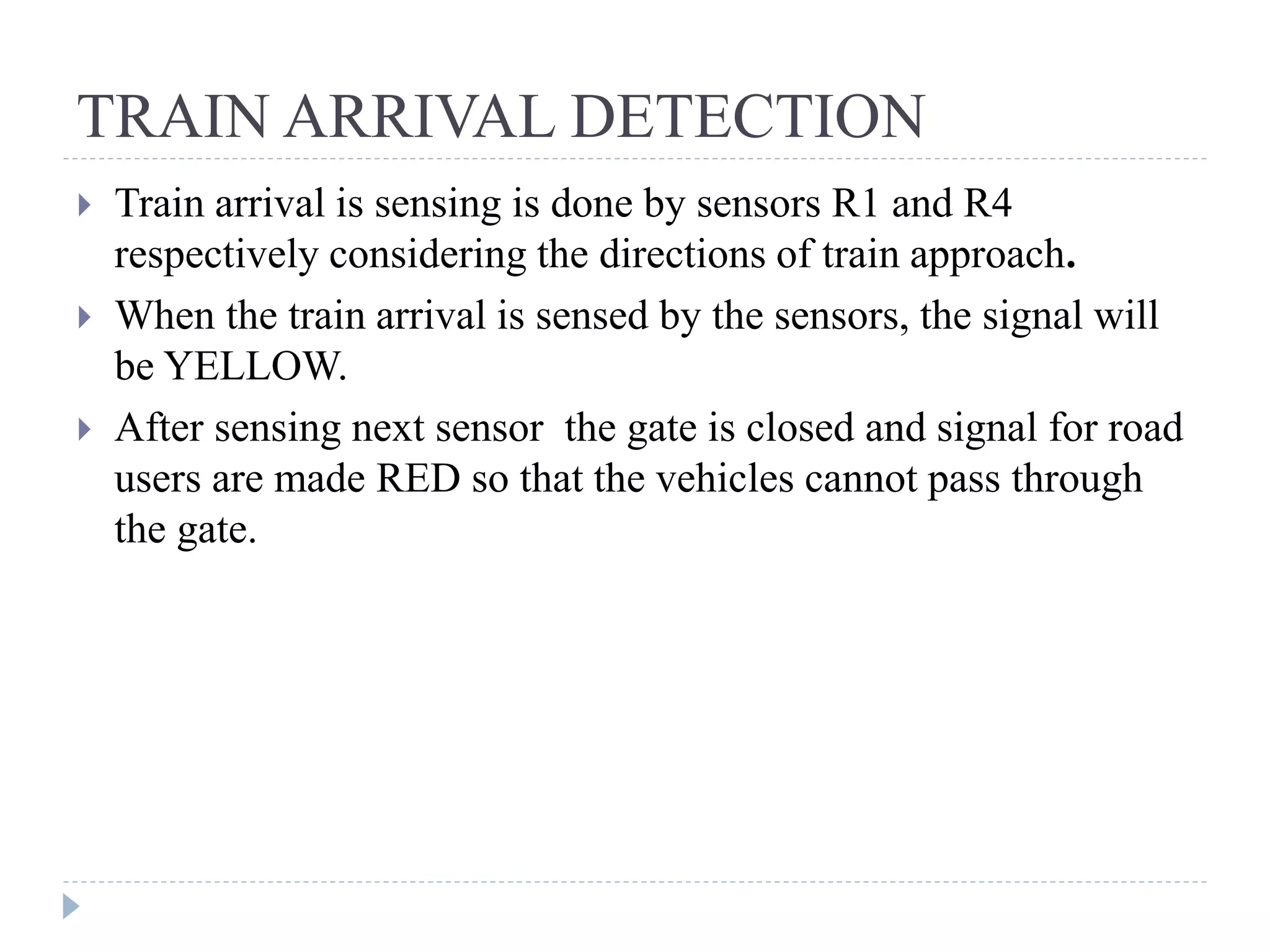
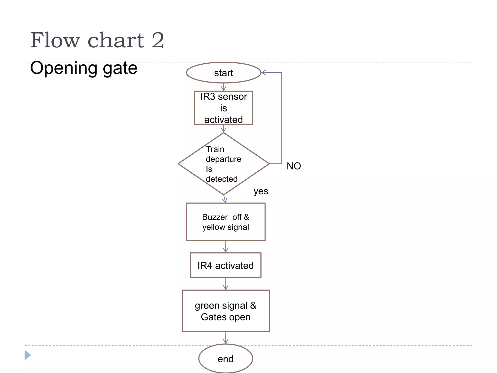
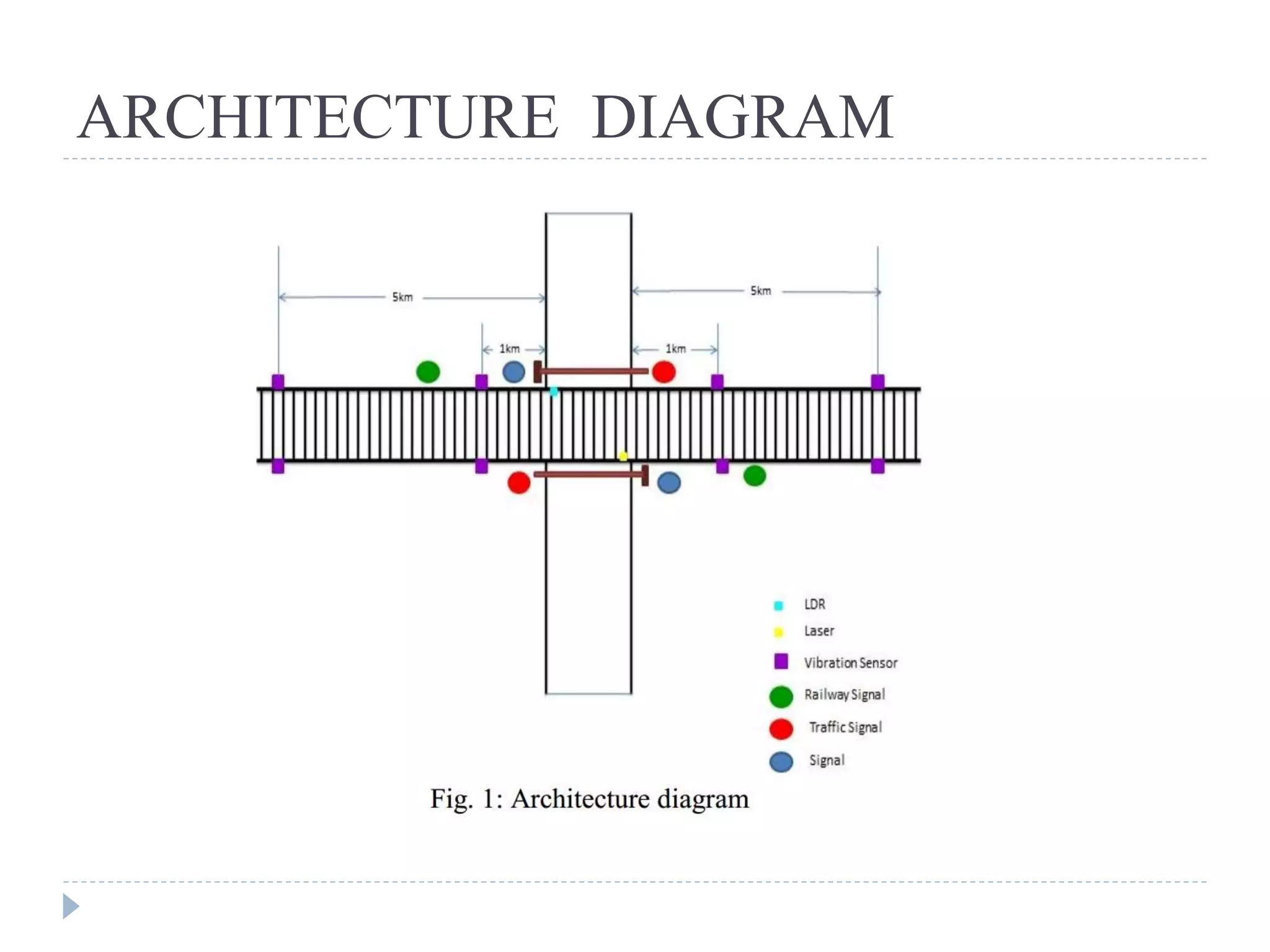


This document describes a project to automate the control of railway crossing gates using Verilog. It uses infrared sensors to detect approaching and departing trains, which triggers the automated opening and closing of the gates. When a train is detected approaching by sensors located 1km and 5km from the crossing, the gate closes and warning signals are activated. When the train departs and is detected by sensors on the other side, the gate reopens and clear signals are shown. The system aims to avoid accidents by removing human error in manual gate operation. Diagrams show the sensor locations and logic flow, and advantages include improved traffic management, safety for road users, and ability to operate unmanned crossings reliably.