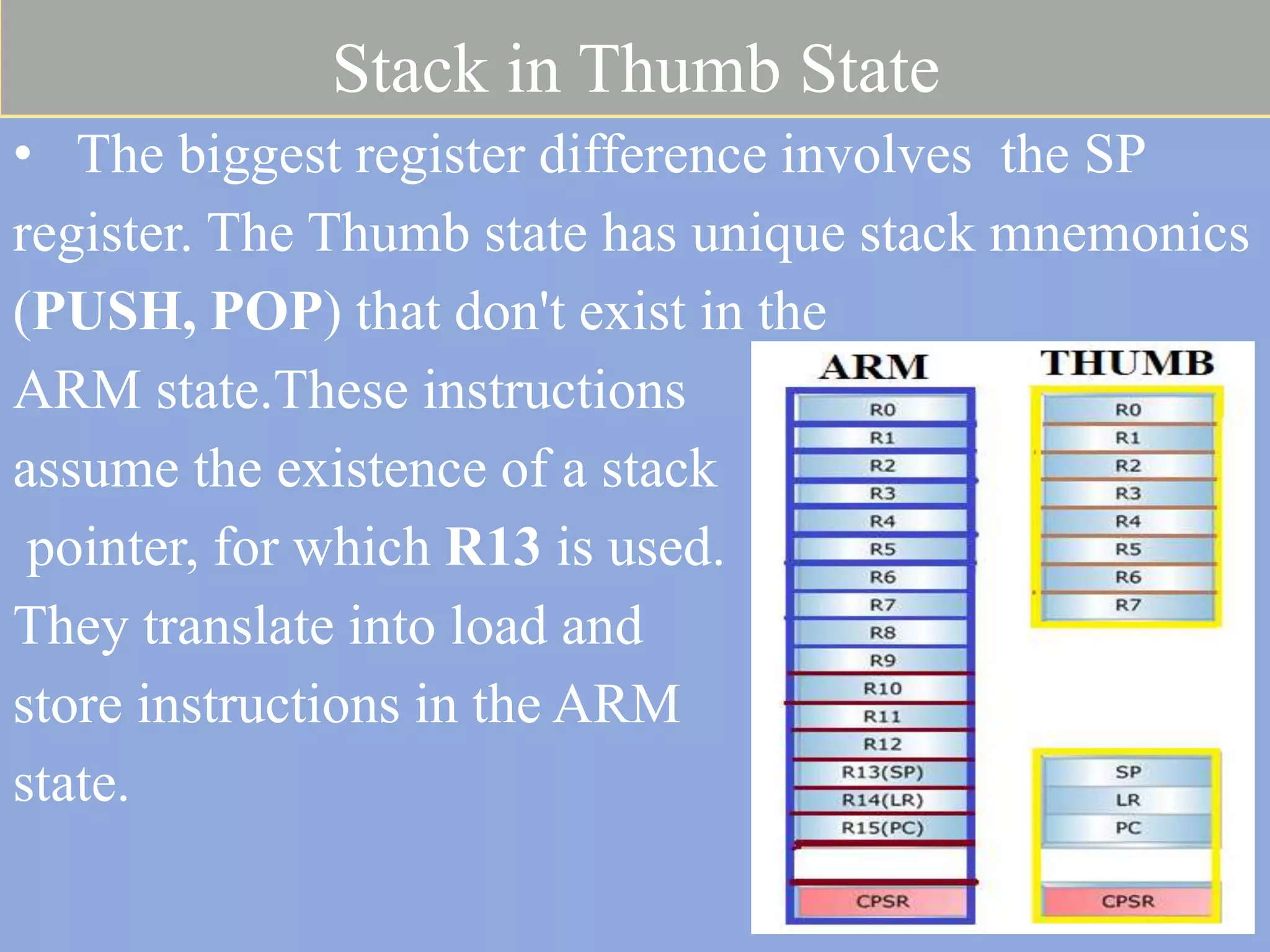
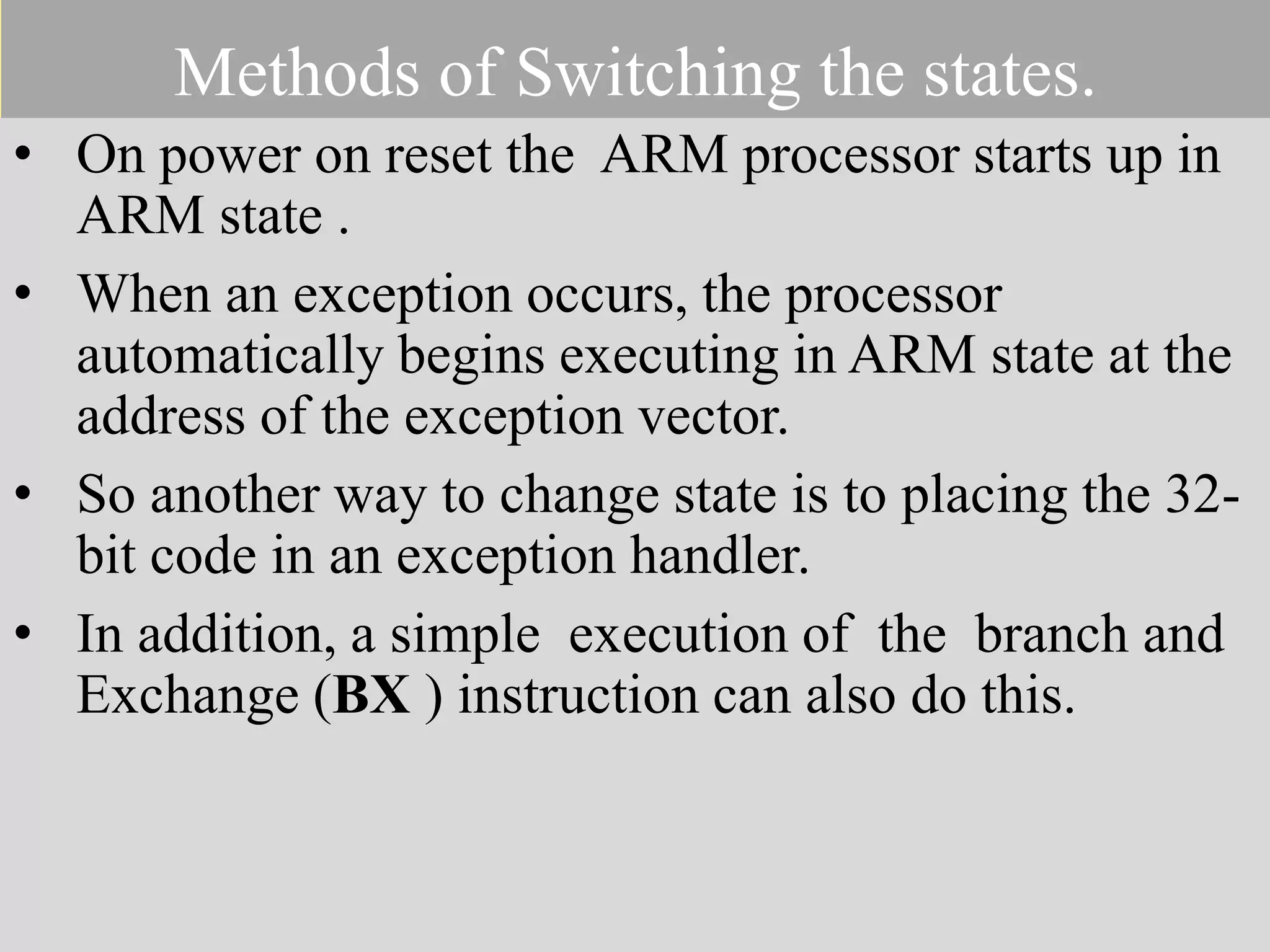
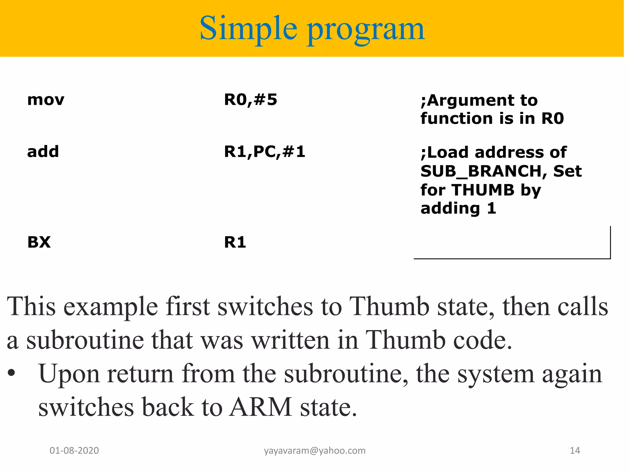
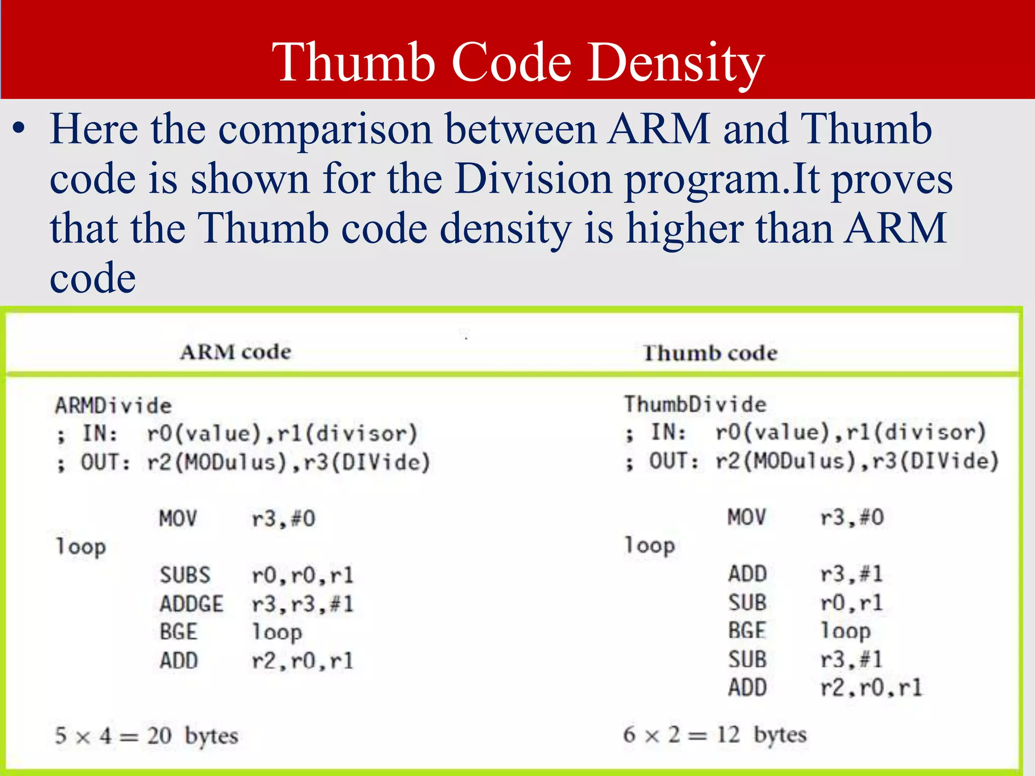
ARM PROCESSOR ARCHITECTUR-4 01-08-2020 yayavaram@yahoo.com 1
• ARM7TDMI (ARM v4) Processor works in two operating states .One is ARM state and the other is Thumb state. • In ARM state instructions are 32 bit wide, and in Thumb state instructions are 16 bit wide. • Thumb mode allows for code to be smaller, and can potentially be faster if the target has slow memory. INTRODUCTION
• The Nintendo Game Boy Advance (GBA) is a portable games console which first used this thumb instruction of ARM7TDMI CPU.Later it was used in PDAs,music players and other gaming applications where memory is very critical. Contd
Why Thumb ? • Except in the high speed embedded devices, the cost of memory is much more critical than the execution speed of the processor. • But all the embedded applications do not need these high speed and memory requirements. • So, to reduce memory requirements and cost, the ARM company has created the Thumb instruction set as an option for their RISC processor cores. • The most well-known chip that includes the Thumb instruction set is the ARM7TDMI. The “T” in the core's full name specifies Thumb. 01-08-2020 yayavaram@yahoo.com 4
contd • The Thumb instruction set consists of 16-bit instructions that act as a compact shorthand for a subset of the 32-bit instructions of the standard ARM. • Every Thumb instruction could instead be executed via the equivalent 32-bit ARM instruction. • But the limitation is not all ARM instructions are available in the Thumb subset , for example, there's no way to access status or coprocessor registers. 01-08-2020 yayavaram@yahoo.com 5
contd 01-08-2020 yayavaram@yahoo.com 6
contd • The difference between two equivalent instructions lies in how the instructions are fetched and interpreted prior to execution, not in how they function. • Since the expansion from 16-bit to 32-bit instruction is accomplished via dedicated hardware within the chip, it doesn't slow execution even a bit. • But the narrower 16-bit instructions do offer memory advantages. 01-08-2020 yayavaram@yahoo.com 7
Block Diagram of ARM7ARM & THUMB states • Upon power on reset , ARM processors always start in ARM state. • To enter to Thumb state the user must explicitly change to Thumb state using a BX (Branch and exchange instruction set) instruction. • The Thumb instruction set is a subset of the 32bit ARM instruction set. • Some of the of 32 bit ARM instructions are not available when operating in THUMB state.
CPSR Register • The T bit of the CPSR Decides whether the processor is 16 bit Thumb state or 32 bit ARM state. • When the T bit is 1, the processor is in Thumb state. • There are also other methods to switch between these state.
contd • A comparison between the two states is given below. • From the table it is clear that no of core instructions is less in Thumb mode.
Thumb State Registers The Thumb state provides a subset of the ARM state, registers: •Eight general purpose registers r0 to r7 (also known as the low registers) • SP register (banked in all modes) • LR register (banked in all modes) • PC register & • CPSR register • SPSR (banked for the privileged modes) . The high registers r8 to r15 are generally not accessible when in the Thumb state (except for the three instructions MOV , ADD, and CMP).
Stack in Thumb State • The biggest register difference involves the SP register. The Thumb state has unique stack mnemonics (PUSH, POP) that don't exist in the ARM state.These instructions assume the existence of a stack pointer, for which R13 is used. They translate into load and store instructions in the ARM state.
Methods of Switching the states. • On power on reset the ARM processor starts up in ARM state . • When an exception occurs, the processor automatically begins executing in ARM state at the address of the exception vector. • So another way to change state is to placing the 32- bit code in an exception handler. • In addition, a simple execution of the branch and Exchange (BX ) instruction can also do this.
Simple program mov R0,#5 ;Argument to function is in R0 add R1,PC,#1 ;Load address of SUB_BRANCH, Set for THUMB by adding 1 BX R1 01-08-2020 yayavaram@yahoo.com 14 This example first switches to Thumb state, then calls a subroutine that was written in Thumb code. • Upon return from the subroutine, the system again switches back to ARM state.
Thumb Code Density • Here the comparison between ARM and Thumb code is shown for the Division program.It proves that the Thumb code density is higher than ARM code
contd • Another important point is that there are no MSR (ARM register to system coprocessor register) and MRS(general-purpose register to PSR) equivalent Thumb instructions. • To alter the CPSR or SPSR , one must switch into ARM state to use MSR and MRS. Similarly, there are no coprocessor instructions in Thumb state. • You need to be in ARM state to access the coprocessor for configuring cache and memory management.
01-08-2020 yayavaram@yahoo.com 17

Lect 4 ARM PROCESSOR ARCHITECTURE

  • 1.
  • 2.
    • ARM7TDMI (ARMv4) Processor works in two operating states .One is ARM state and the other is Thumb state. • In ARM state instructions are 32 bit wide, and in Thumb state instructions are 16 bit wide. • Thumb mode allows for code to be smaller, and can potentially be faster if the target has slow memory. INTRODUCTION
  • 3.
    • The NintendoGame Boy Advance (GBA) is a portable games console which first used this thumb instruction of ARM7TDMI CPU.Later it was used in PDAs,music players and other gaming applications where memory is very critical. Contd
  • 4.
    Why Thumb ? •Except in the high speed embedded devices, the cost of memory is much more critical than the execution speed of the processor. • But all the embedded applications do not need these high speed and memory requirements. • So, to reduce memory requirements and cost, the ARM company has created the Thumb instruction set as an option for their RISC processor cores. • The most well-known chip that includes the Thumb instruction set is the ARM7TDMI. The “T” in the core's full name specifies Thumb. 01-08-2020 yayavaram@yahoo.com 4
  • 5.
    contd • The Thumbinstruction set consists of 16-bit instructions that act as a compact shorthand for a subset of the 32-bit instructions of the standard ARM. • Every Thumb instruction could instead be executed via the equivalent 32-bit ARM instruction. • But the limitation is not all ARM instructions are available in the Thumb subset , for example, there's no way to access status or coprocessor registers. 01-08-2020 yayavaram@yahoo.com 5
  • 6.
  • 7.
    contd • The differencebetween two equivalent instructions lies in how the instructions are fetched and interpreted prior to execution, not in how they function. • Since the expansion from 16-bit to 32-bit instruction is accomplished via dedicated hardware within the chip, it doesn't slow execution even a bit. • But the narrower 16-bit instructions do offer memory advantages. 01-08-2020 yayavaram@yahoo.com 7
  • 8.
    Block Diagram ofARM7ARM & THUMB states • Upon power on reset , ARM processors always start in ARM state. • To enter to Thumb state the user must explicitly change to Thumb state using a BX (Branch and exchange instruction set) instruction. • The Thumb instruction set is a subset of the 32bit ARM instruction set. • Some of the of 32 bit ARM instructions are not available when operating in THUMB state.
  • 9.
    CPSR Register • TheT bit of the CPSR Decides whether the processor is 16 bit Thumb state or 32 bit ARM state. • When the T bit is 1, the processor is in Thumb state. • There are also other methods to switch between these state.
  • 10.
    contd • A comparisonbetween the two states is given below. • From the table it is clear that no of core instructions is less in Thumb mode.
  • 11.
    Thumb State Registers TheThumb state provides a subset of the ARM state, registers: •Eight general purpose registers r0 to r7 (also known as the low registers) • SP register (banked in all modes) • LR register (banked in all modes) • PC register & • CPSR register • SPSR (banked for the privileged modes) . The high registers r8 to r15 are generally not accessible when in the Thumb state (except for the three instructions MOV , ADD, and CMP).
  • 12.
    Stack in ThumbState • The biggest register difference involves the SP register. The Thumb state has unique stack mnemonics (PUSH, POP) that don't exist in the ARM state.These instructions assume the existence of a stack pointer, for which R13 is used. They translate into load and store instructions in the ARM state.
  • 13.
    Methods of Switchingthe states. • On power on reset the ARM processor starts up in ARM state . • When an exception occurs, the processor automatically begins executing in ARM state at the address of the exception vector. • So another way to change state is to placing the 32- bit code in an exception handler. • In addition, a simple execution of the branch and Exchange (BX ) instruction can also do this.
  • 14.
    Simple program mov R0,#5;Argument to function is in R0 add R1,PC,#1 ;Load address of SUB_BRANCH, Set for THUMB by adding 1 BX R1 01-08-2020 yayavaram@yahoo.com 14 This example first switches to Thumb state, then calls a subroutine that was written in Thumb code. • Upon return from the subroutine, the system again switches back to ARM state.
  • 15.
    Thumb Code Density •Here the comparison between ARM and Thumb code is shown for the Division program.It proves that the Thumb code density is higher than ARM code
  • 16.
    contd • Another importantpoint is that there are no MSR (ARM register to system coprocessor register) and MRS(general-purpose register to PSR) equivalent Thumb instructions. • To alter the CPSR or SPSR , one must switch into ARM state to use MSR and MRS. Similarly, there are no coprocessor instructions in Thumb state. • You need to be in ARM state to access the coprocessor for configuring cache and memory management.
  • 17.