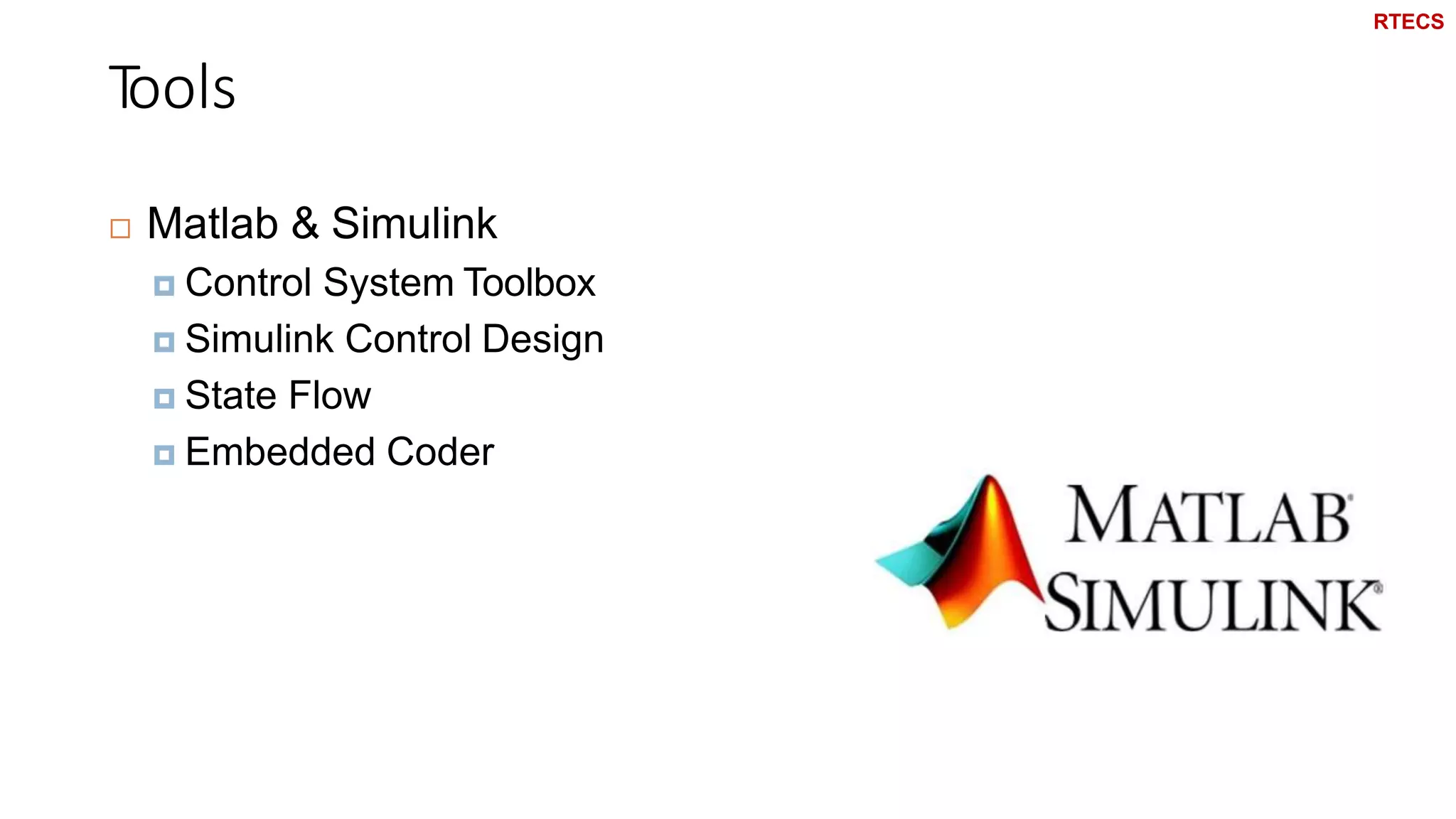
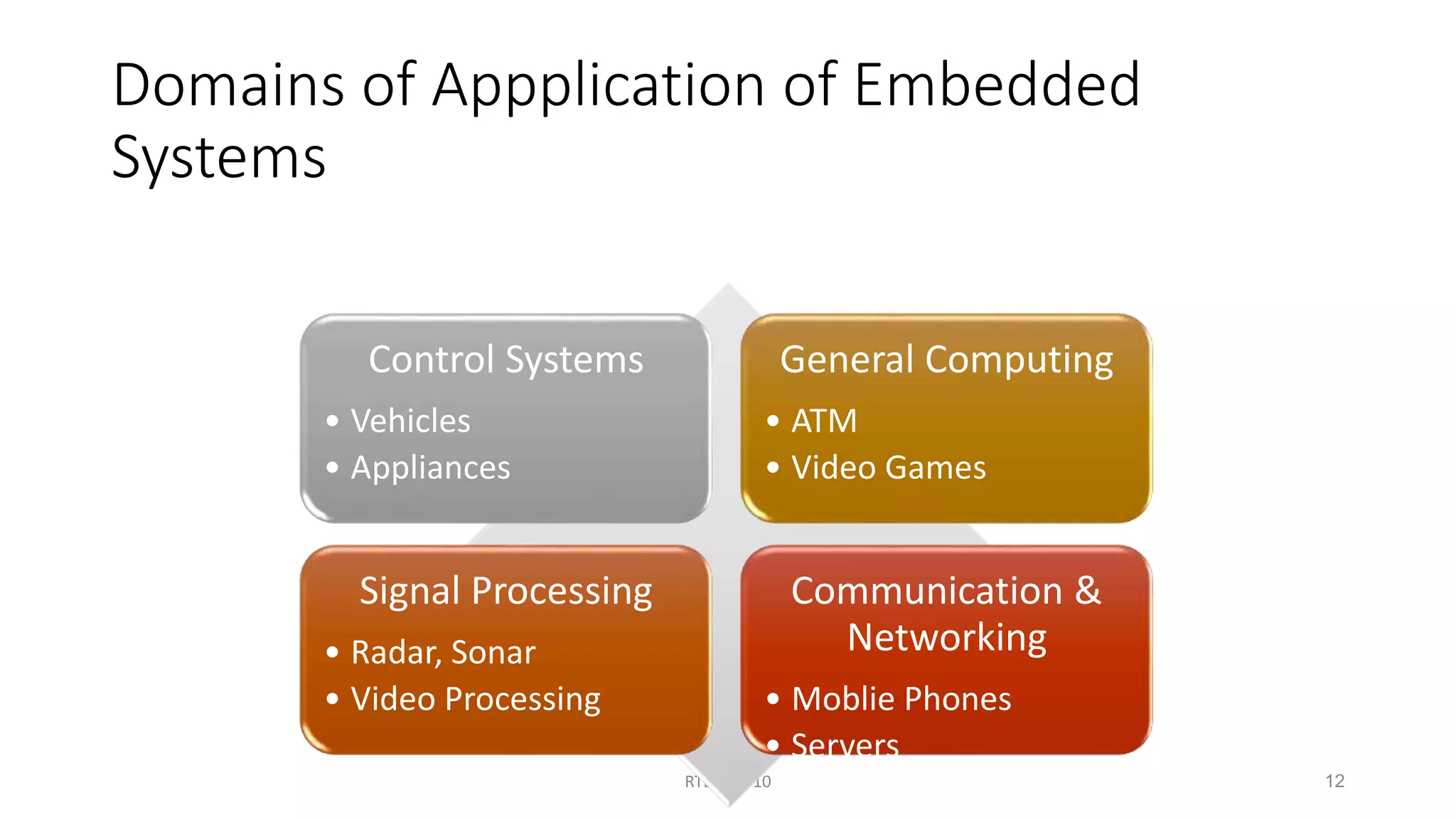
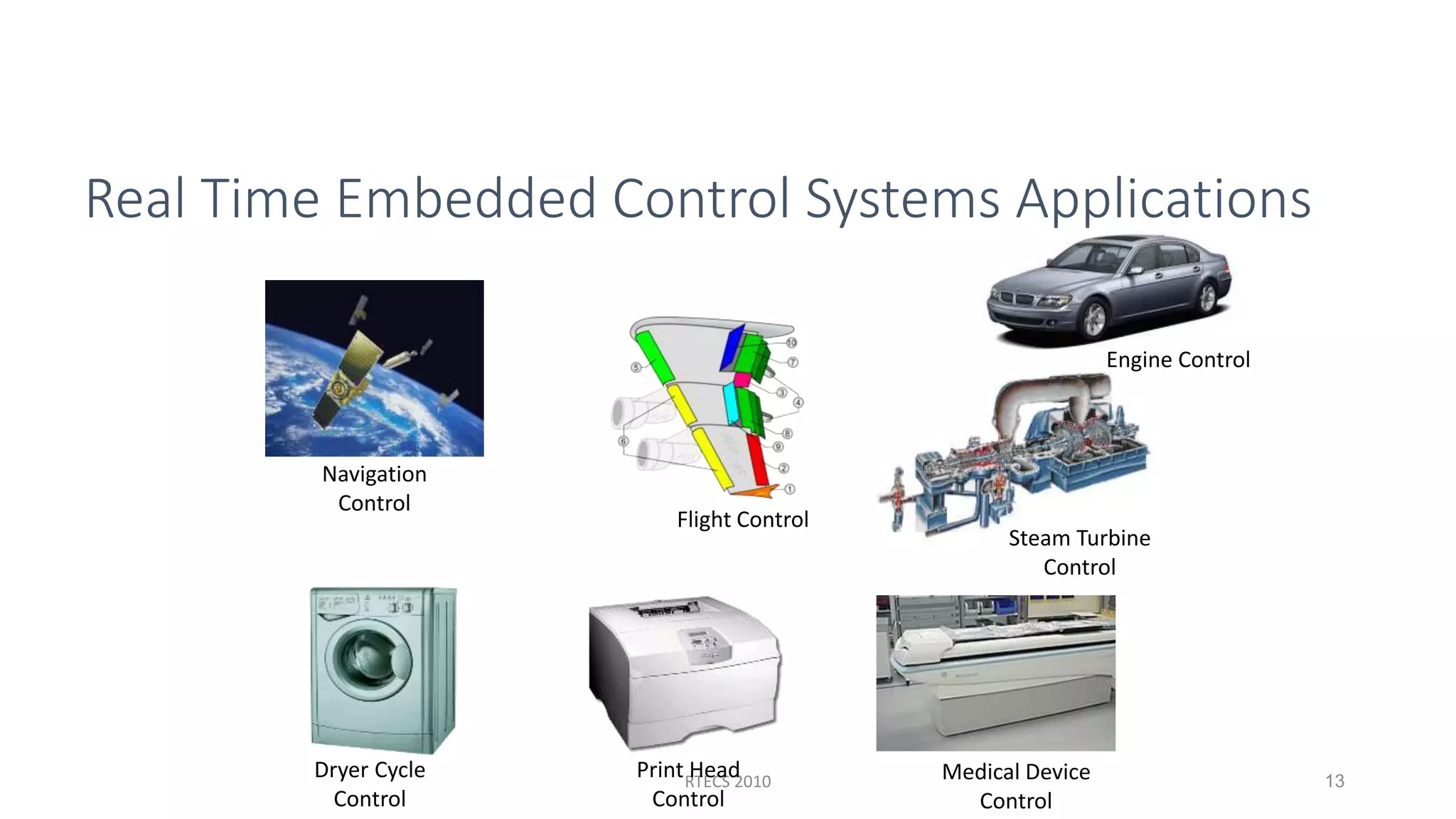
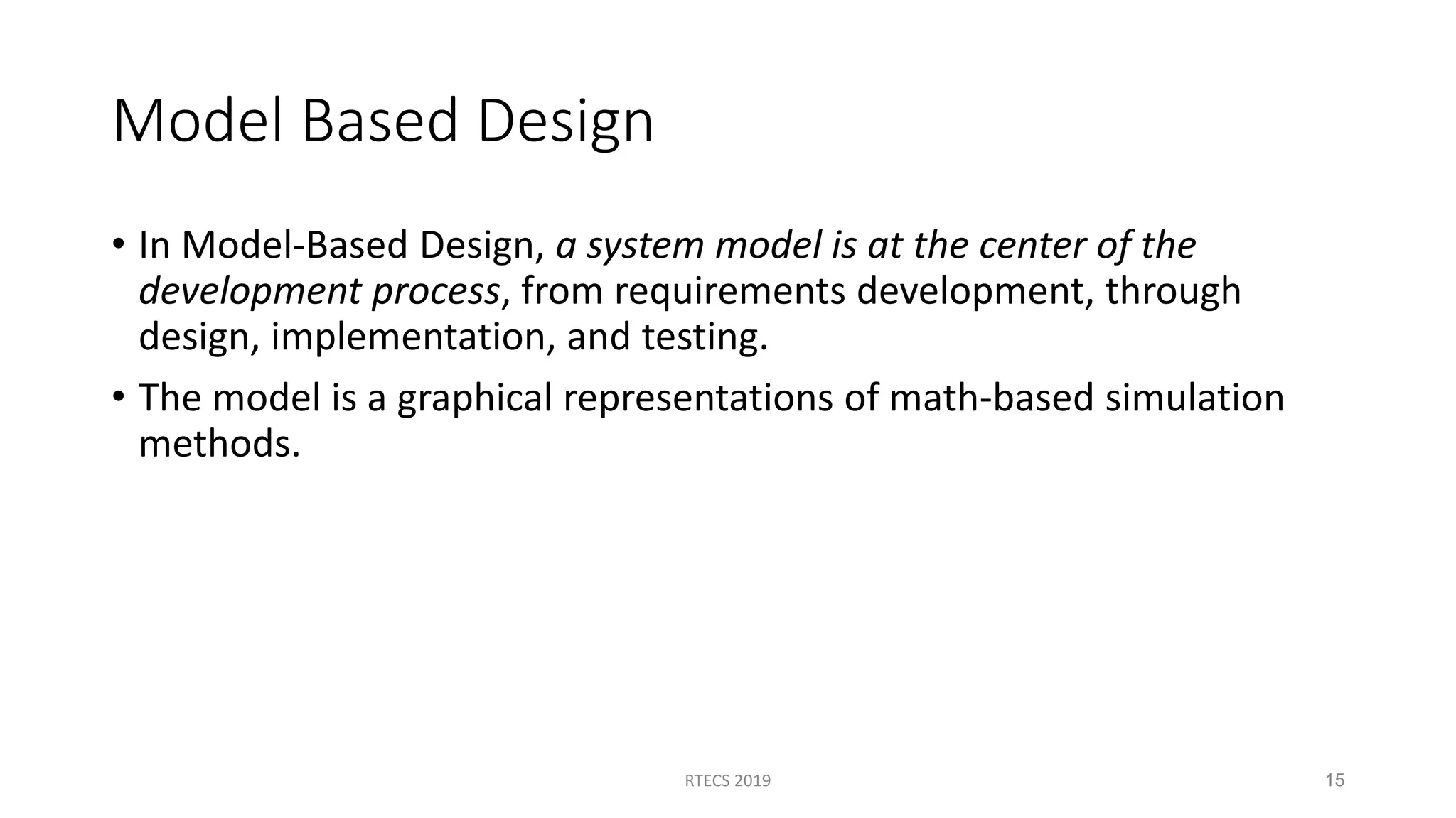
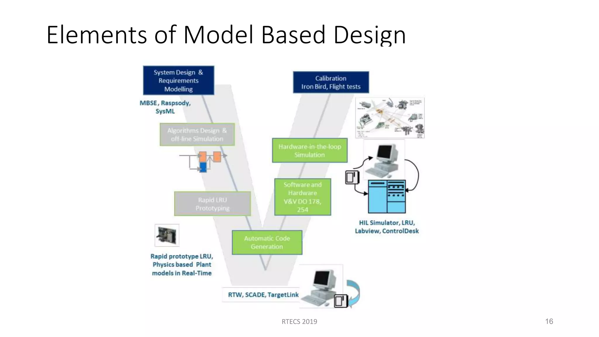
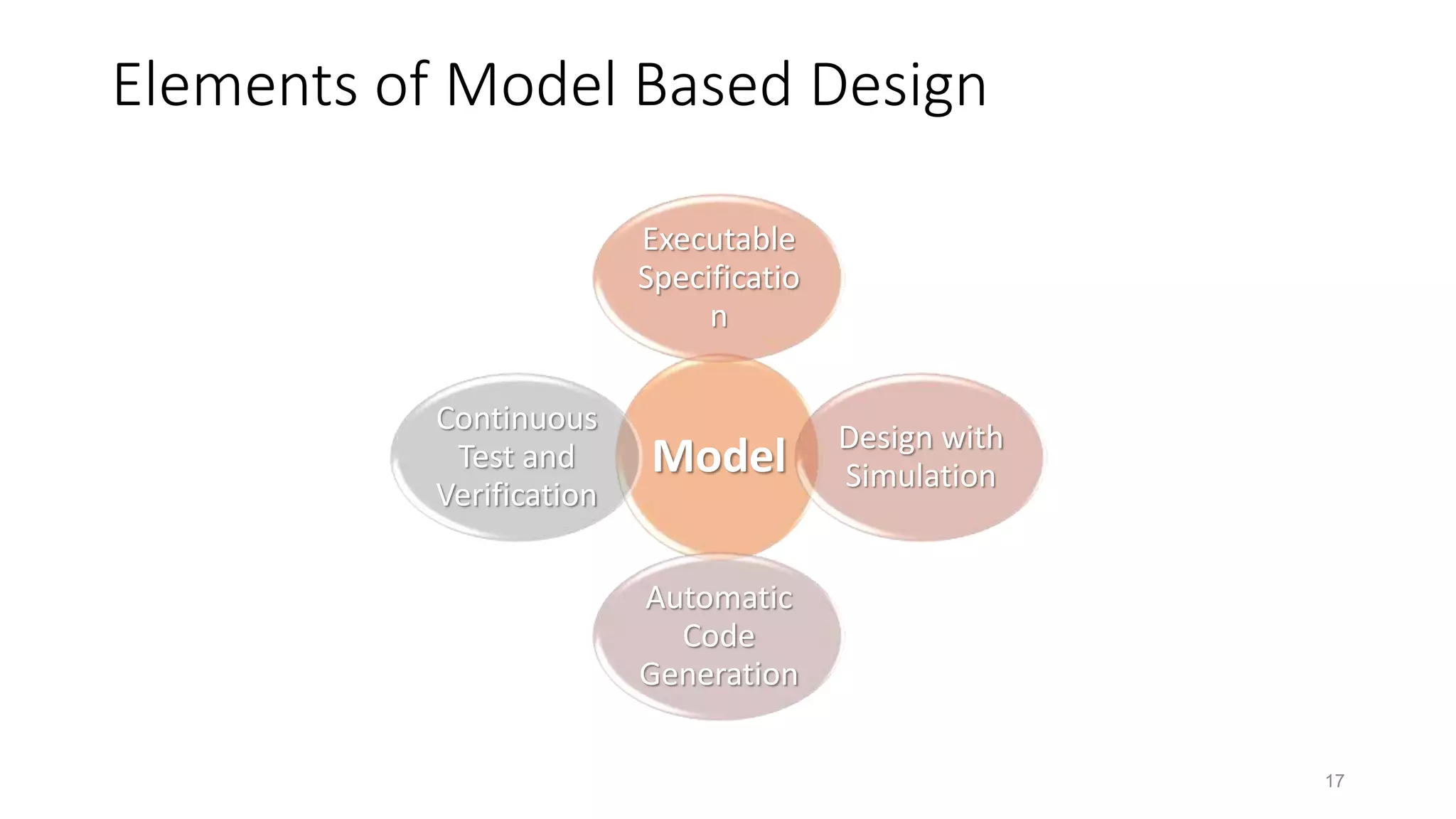
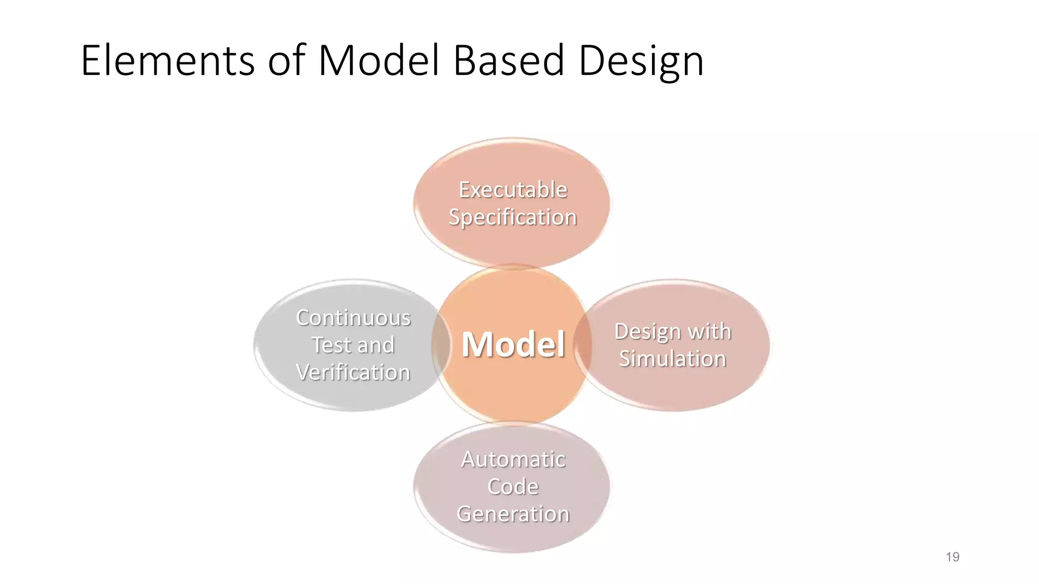
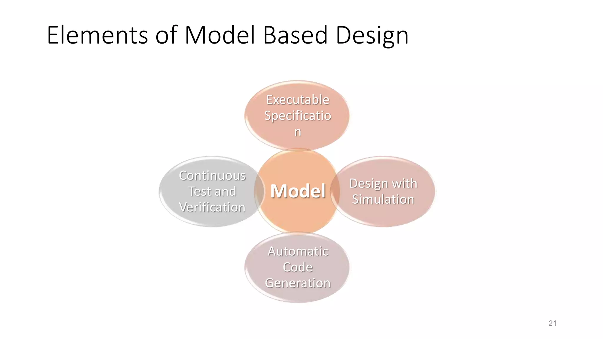
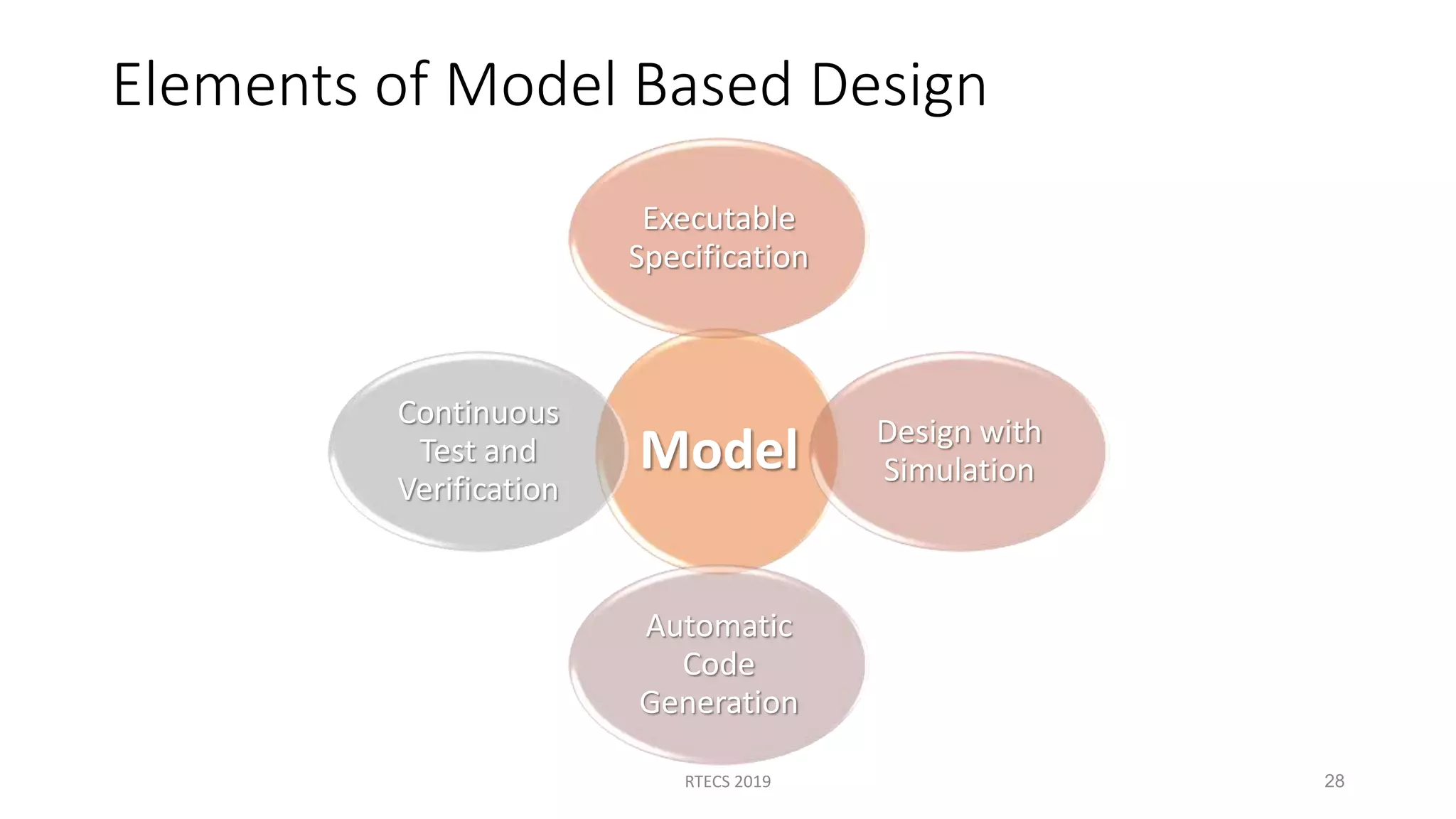
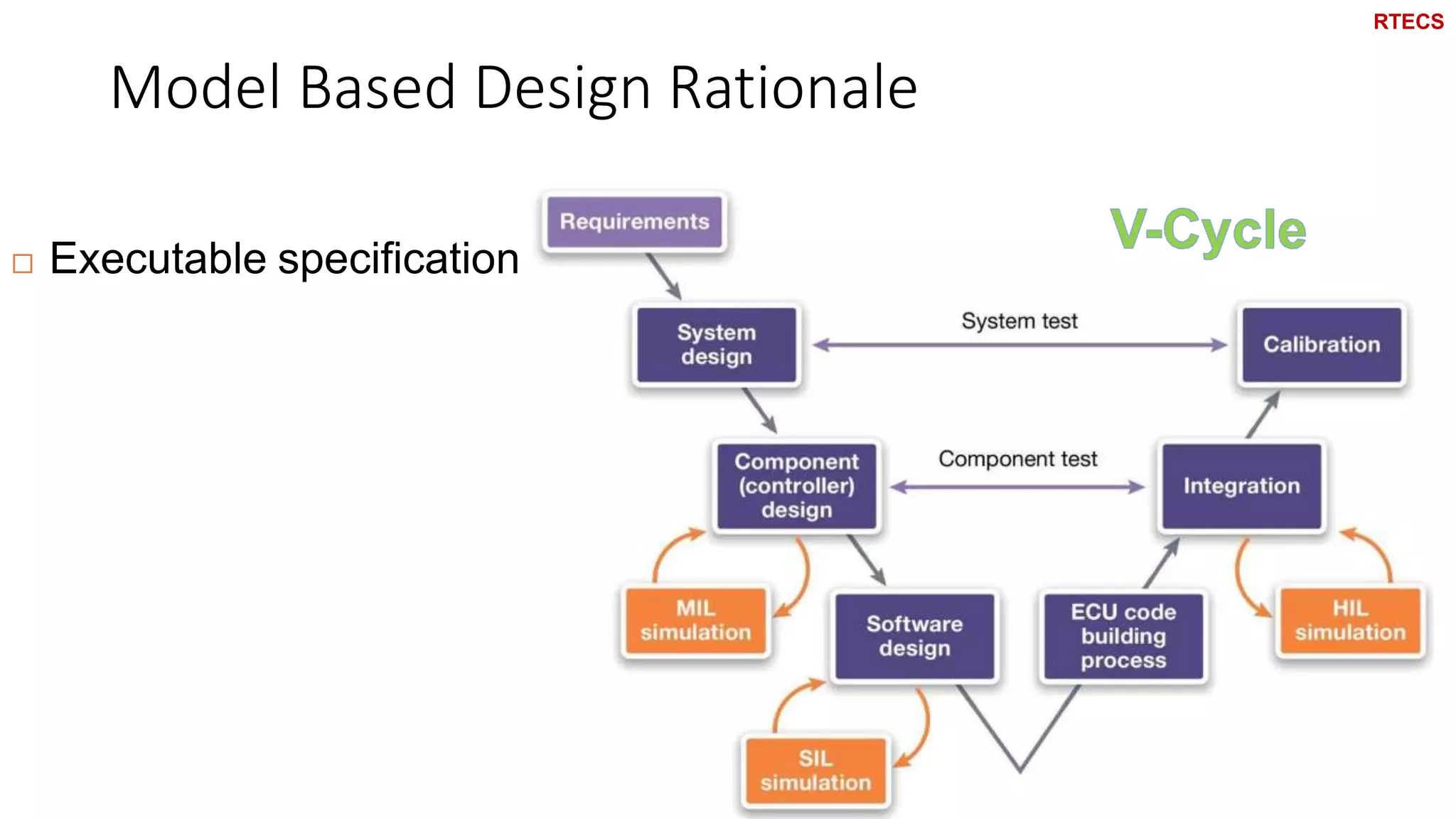
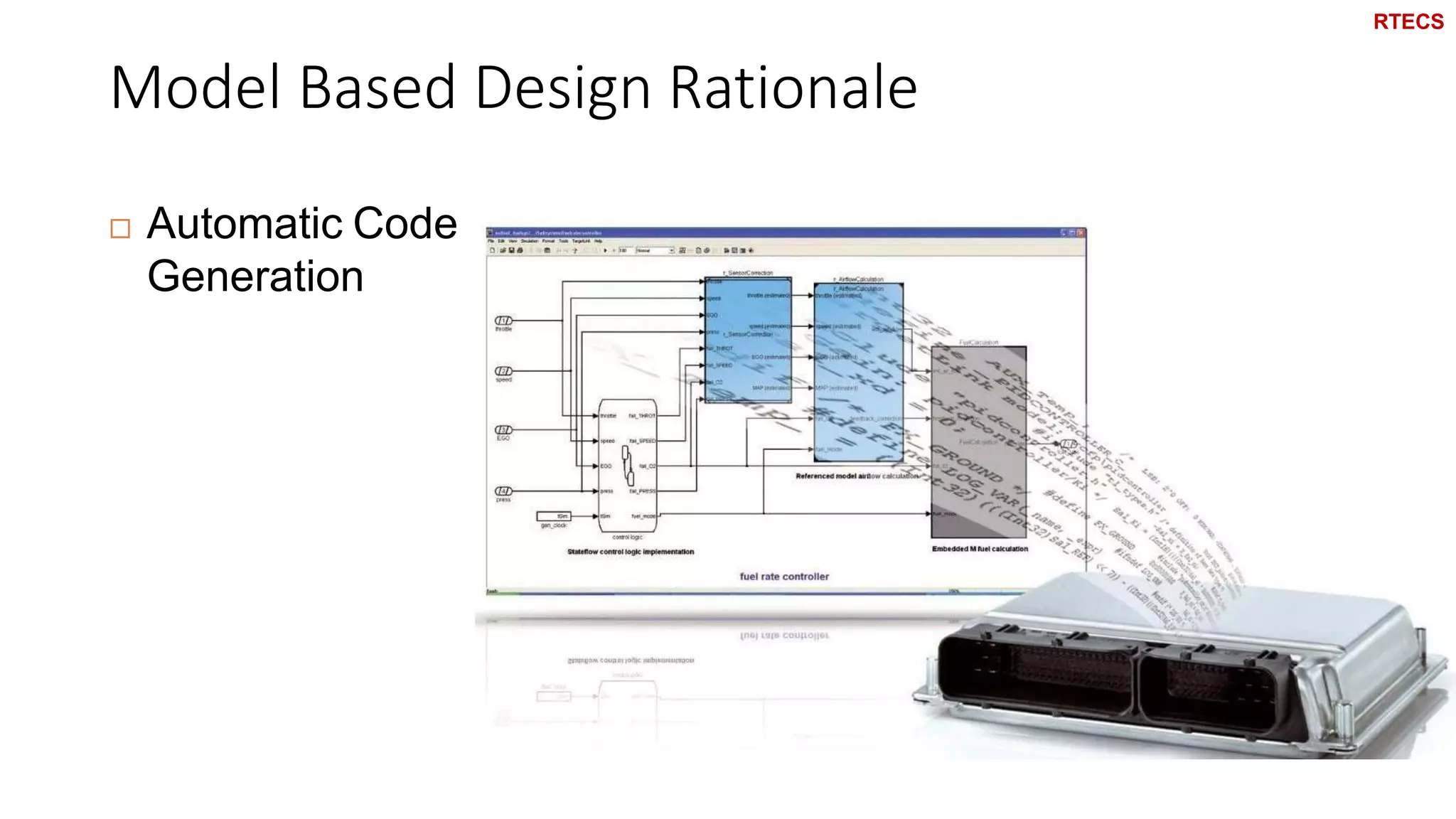
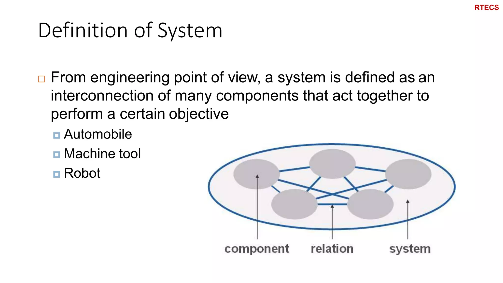
REAL TIME EMBEDDED CONTROL SYSTEMS USING MBD CONCEPT Eng. Mahmoud Hussein 18-oct-19 RTECS 2019 1
Contact Person 2  Course Instructor  Mahmoud Hussein  Lecturer assistant, French university  Email: Mahmoud.ahmed2013@gmail.com  Mobile: 01007148378 RTECS
Rules 13 RTECS
‫الذكية‬ ‫للصواريخ‬ ‫القومى‬ ‫المشروع‬ 4 Which methodology will you use to develop a SAM? A: Manually Write Assembly B: Manually Write C-Code C: MBD: Auto-Code Generation RTECS
Welcome to Real Time Embedded Control Systems RTECS
Course Objective 6  The course shows one design path for real time embedded systems.  It starts by system level simulation based design.  It ends by real time implementation of control algorithms. RTECS
Course Syllabus 7  Part 1 : Introduction to Matlab and Simulink  Recognize MATLAB and Simulink Environment  MATLAB Fundamentals and Basic Operations  M-File and Programming Basics  Data Visualization (2D/3D)  State flow.  S-function RTECS
Course Syllabus 8 Part 2 : Basics and Modelling  Introduction to Real Time Embedded Control Systems  Physical System Modelling of Mechanical Systems  Dynamic SystemAnalysis  Physical System Modelling of Electrical Systems  Modelling Electric Motors RTECS
Course Syllabus 9 Part 3: Control and PID  Control Systems  PID Controller  Tuning PID Controllers  Numerical Integration  PID Advanced Topics  Digital Controller Design RTECS
Course Syllabus 10 Part 4: Advanced Topics  Embedded Coder .  State Machine Concept.  MathWorks Automotive Advisory Board- MAAB(Optional) RTECS
Tools 11  Matlab & Simulink  Control System Toolbox  Simulink Control Design  State Flow  Embedded Coder RTECS
Domains of Appplication of Embedded Systems RTECS 2010 12 Control Systems • Vehicles • Appliances General Computing • ATM • Video Games Signal Processing • Radar, Sonar • Video Processing Communication & Networking • Moblie Phones • Servers
Real Time Embedded Control Systems Applications RTECS 2010 13 Steam Turbine Control Flight Control Print Head Control Navigation Control Engine Control Dryer Cycle Control Medical Device Control
Model Based Design RTECS
Model Based Design • In Model-Based Design, a system model is at the center of the development process, from requirements development, through design, implementation, and testing. • The model is a graphical representations of math-based simulation methods. RTECS 2019 15
Elements of Model Based Design RTECS 2019 16
Elements of Model Based Design 17 Model Executable Specificatio n Design with Simulation Automatic Code Generation Continuous Test and Verification
Executable Specification • Executable • The model can be simulated to illustrate functional behavior. • Specification • An explicit design intended to meet certain requirements. 18
Elements of Model Based Design 19 Model Executable Specification Design with Simulation Automatic Code Generation Continuous Test and Verification
Design with Simulation • Use simulate during the design stage to verify that the model meets the requirements, detect and correct errors early in the design stage 20
Elements of Model Based Design 21 Model Executable Specificatio n Design with Simulation Automatic Code Generation Continuous Test and Verification
Coding Traditional Approach RTECS 2010 22 Problems: • Communication • Ambiguity of specs • Resource conflicts  Large turnaround time! Production Code Specs Function Developer  algorithm knowledge #include <math.h> if (a > 0) ki = 0.4*x+z1; Software Specialist  implementation & coding knowledge Time
Automatic Code Generation RTECS 2010 23 Function Developer  algorithm knowledge Software Specialist  implementation knowledge Coding knowledge: • ANSI-C • language extensions • assembly language • processor architecture  … and how to optimally use it! Code Generator  coding knowledge
Automatic Code Generation Features • Scheduling and integration with RTOS • MISRA C • Autosar • Customizable code 24
Automatic Code Generators • TargetLink from dSPACE, since 1999 • Real-Time Workshop Embedded Coder from MathWorks RTECS 2010 25
Automatic Code Generation RTECS 2019 26 Implementation Model (fixed-point) C CodeCode generator Compiler (Linker) Host PC Target Physical Model (floating-point) Cross-compiler (Linker / Loader)
Automatic Code Generation RTECS 2019 27 Implementation Model (fixed-point) C CodeCode generator Compiler (Linker) Host PC Target Physical Model (floating-point) Cross-compiler (Linker / Loader)
Elements of Model Based Design RTECS 2019 28 Model Executable Specification Design with Simulation Automatic Code Generation Continuous Test and Verification
Continuous Test and Verification • Deign test cases to test the model • Reuse test cases to test software implementation • Simulation models enable to test conditions that would be destructive or cost-prohibitive to run in the lab or on the road • Automatically generating test cases from the model to ensure Modified Condition/Decision Coverage (MC/DC) • Writing the MC/DC tests would take as least as long as the original design effort RTECS 2019 29
RTECS 2010 30    test output result comparison physical model implementation model test stimuli C code (target) ECU MiL (physical model) MiL (impl. model) SiL PiL C code (host)
Model in the Loop (MIL) • Proof of Concept and Design Optimization • Pure simulation • Modelling of both the application and the environment may be wrong 31 Controller running in e.g. Simulink Plant running in e.g. Simulink
Software in the Loop (SIL) • Compiled application • Simulation at an early stage • Accelerated simulation • Low cost & short development time • Non real-time RTECS 2010 32 Controller running as binary Plant running in e.g. Simulink
Processor in the Loop (PIL) • Determining Memory Usage • Determining the time needed for the Algorithm • Assures that the tool chain does not cause problems • Determining problems related to the resolution of the processor (16 bits, 32 bits, fixed point) 33 Controller running on target HW Plant running in e.g. Simulink
MIL SIL PIL RTECS 2010 34
Hardware in the Loop (HIL) • HIL system replaces the real world environment • Production hardware can be tested without any changes • Application is executed in real time on an appropriate hardware platform RTECS 2010 35 Controller running on target Plant Running in real-time on a HIL Simulator
HIL Simulator: dSPACE RTECS 2010 36 Dynamic Models Processor Board I/O Board GUI and Automation Diagn. Tool ECU Loads FIU
User Interface for Interactive Use of the HIL System RTECS 2010 37
Networked HIL Simulation 38 Vehicle dynamics Comfort (central unit) Transmission Engine GigaLink CAN 2004 Audi A6
Networked HIL Simulation RTECS 2010 39 Mercedes-Benz 2005 A-Class Breadboard Table appr. 8 powertrain and chassis ECUs appr. 20 body ECUs
What is a Model? RTECS 2014 15 RTECS
What is a Model? 16 A model is a representation of a real system focusing onsome important aspects  Scale model  Represents geometric proportions  Flight simulator  Focuses on flight dynamics RTECS
What is a Model? 17  In Model-Based Design, a system model is at the center of the development process, from requirements development, through design, implementation, and testing.  What is meant here by model is a graphical representations of the system RTECS
Model Based Design Rationale 18  Think: can you draw a rectangle with 3 lines RTECS
Model Based Design Rationale 19  Executable specification RTECS
Model Based Design Rationale 20  Automatic Code Generation RTECS
Model Based Design Rationale 21 1. Graphical Representation 2. Executable Specification 3. Automatic Code Generation RTECS
Physical Systems RTECS
Definition of System 23  From engineering point of view, a system is defined as an interconnection of many components that act together to perform a certain objective  Automobile  Machine tool  Robot RTECS
Physical Systems Classification 24 Physical System Static System Dynamic System RTECS
Static System 25  Output of the system depends only on the current input  The system has no memory RTECS
Dynamic System 26  Output of the system depends on the current input as well as previous inputs/outputs  The system has internal memory A dynamic system can be represented mathematically using differential equations RTECS
What is a Real Time System? RTECS
Real-Time System 43  A real-time system is a software system where the correct functioning of the system depends not only on the results produced by the system but also on the time at which these results are produced.  The system has "real-time constraints" RTECS
Hard Real-Time System 44  A hard real-time system is a system whose operation is incorrectif results are not produced according to the timing specification.  Car engine control system is a hard real-time system  because a delayed signal may cause engine failure or damage  Flight Control System  Airbag crash detection system RTECS
Hard Real-Time System 45  Delay = Failure  Time granularity  Millisecond  RequiredAnalysis  Worst possible scenario  Need for redundancy  To meet safety requirements RTECS
Hard Real-Time System Example 46  Airbag crash detection system  Airbag must inflate between 10 and 20 msec from the detection of a crash  Not too early—since this would make the airbag deflate before it can catch the passenger  Nor too late—since the airbag could then injure the passenger by blowing up in his face and/or catch him too late to prevent his head from banging into the steering wheel RTECS
Soft Real-Time System 47  A soft real-time system is a system whose operation is degraded if results are not produced according to the specified timing requirements.  Non-safety-critical system  Keypad input  Message visualization  System status representation RTECS

Model based design-Hardware in loop-software in loop

  • 1.
    REAL TIME EMBEDDEDCONTROL SYSTEMS USING MBD CONCEPT Eng. Mahmoud Hussein 18-oct-19 RTECS 2019 1
  • 2.
    Contact Person 2  CourseInstructor  Mahmoud Hussein  Lecturer assistant, French university  Email: Mahmoud.ahmed2013@gmail.com  Mobile: 01007148378 RTECS
  • 3.
  • 4.
    ‫الذكية‬ ‫للصواريخ‬ ‫القومى‬‫المشروع‬ 4 Which methodology will you use to develop a SAM? A: Manually Write Assembly B: Manually Write C-Code C: MBD: Auto-Code Generation RTECS
  • 5.
    Welcome to Real TimeEmbedded Control Systems RTECS
  • 6.
    Course Objective 6  Thecourse shows one design path for real time embedded systems.  It starts by system level simulation based design.  It ends by real time implementation of control algorithms. RTECS
  • 7.
    Course Syllabus 7  Part1 : Introduction to Matlab and Simulink  Recognize MATLAB and Simulink Environment  MATLAB Fundamentals and Basic Operations  M-File and Programming Basics  Data Visualization (2D/3D)  State flow.  S-function RTECS
  • 8.
    Course Syllabus 8 Part 2: Basics and Modelling  Introduction to Real Time Embedded Control Systems  Physical System Modelling of Mechanical Systems  Dynamic SystemAnalysis  Physical System Modelling of Electrical Systems  Modelling Electric Motors RTECS
  • 9.
    Course Syllabus 9 Part 3:Control and PID  Control Systems  PID Controller  Tuning PID Controllers  Numerical Integration  PID Advanced Topics  Digital Controller Design RTECS
  • 10.
    Course Syllabus 10 Part 4:Advanced Topics  Embedded Coder .  State Machine Concept.  MathWorks Automotive Advisory Board- MAAB(Optional) RTECS
  • 11.
    Tools 11  Matlab &Simulink  Control System Toolbox  Simulink Control Design  State Flow  Embedded Coder RTECS
  • 12.
    Domains of Appplicationof Embedded Systems RTECS 2010 12 Control Systems • Vehicles • Appliances General Computing • ATM • Video Games Signal Processing • Radar, Sonar • Video Processing Communication & Networking • Moblie Phones • Servers
  • 13.
    Real Time EmbeddedControl Systems Applications RTECS 2010 13 Steam Turbine Control Flight Control Print Head Control Navigation Control Engine Control Dryer Cycle Control Medical Device Control
  • 14.
  • 15.
    Model Based Design •In Model-Based Design, a system model is at the center of the development process, from requirements development, through design, implementation, and testing. • The model is a graphical representations of math-based simulation methods. RTECS 2019 15
  • 16.
    Elements of ModelBased Design RTECS 2019 16
  • 17.
    Elements of ModelBased Design 17 Model Executable Specificatio n Design with Simulation Automatic Code Generation Continuous Test and Verification
  • 18.
    Executable Specification • Executable •The model can be simulated to illustrate functional behavior. • Specification • An explicit design intended to meet certain requirements. 18
  • 19.
    Elements of ModelBased Design 19 Model Executable Specification Design with Simulation Automatic Code Generation Continuous Test and Verification
  • 20.
    Design with Simulation •Use simulate during the design stage to verify that the model meets the requirements, detect and correct errors early in the design stage 20
  • 21.
    Elements of ModelBased Design 21 Model Executable Specificatio n Design with Simulation Automatic Code Generation Continuous Test and Verification
  • 22.
    Coding Traditional Approach RTECS2010 22 Problems: • Communication • Ambiguity of specs • Resource conflicts  Large turnaround time! Production Code Specs Function Developer  algorithm knowledge #include <math.h> if (a > 0) ki = 0.4*x+z1; Software Specialist  implementation & coding knowledge Time
  • 23.
    Automatic Code Generation RTECS2010 23 Function Developer  algorithm knowledge Software Specialist  implementation knowledge Coding knowledge: • ANSI-C • language extensions • assembly language • processor architecture  … and how to optimally use it! Code Generator  coding knowledge
  • 24.
    Automatic Code GenerationFeatures • Scheduling and integration with RTOS • MISRA C • Autosar • Customizable code 24
  • 25.
    Automatic Code Generators •TargetLink from dSPACE, since 1999 • Real-Time Workshop Embedded Coder from MathWorks RTECS 2010 25
  • 26.
    Automatic Code Generation RTECS2019 26 Implementation Model (fixed-point) C CodeCode generator Compiler (Linker) Host PC Target Physical Model (floating-point) Cross-compiler (Linker / Loader)
  • 27.
    Automatic Code Generation RTECS2019 27 Implementation Model (fixed-point) C CodeCode generator Compiler (Linker) Host PC Target Physical Model (floating-point) Cross-compiler (Linker / Loader)
  • 28.
    Elements of ModelBased Design RTECS 2019 28 Model Executable Specification Design with Simulation Automatic Code Generation Continuous Test and Verification
  • 29.
    Continuous Test andVerification • Deign test cases to test the model • Reuse test cases to test software implementation • Simulation models enable to test conditions that would be destructive or cost-prohibitive to run in the lab or on the road • Automatically generating test cases from the model to ensure Modified Condition/Decision Coverage (MC/DC) • Writing the MC/DC tests would take as least as long as the original design effort RTECS 2019 29
  • 30.
    RTECS 2010 30    test output result comparison physicalmodel implementation model test stimuli C code (target) ECU MiL (physical model) MiL (impl. model) SiL PiL C code (host)
  • 31.
    Model in theLoop (MIL) • Proof of Concept and Design Optimization • Pure simulation • Modelling of both the application and the environment may be wrong 31 Controller running in e.g. Simulink Plant running in e.g. Simulink
  • 32.
    Software in theLoop (SIL) • Compiled application • Simulation at an early stage • Accelerated simulation • Low cost & short development time • Non real-time RTECS 2010 32 Controller running as binary Plant running in e.g. Simulink
  • 33.
    Processor in theLoop (PIL) • Determining Memory Usage • Determining the time needed for the Algorithm • Assures that the tool chain does not cause problems • Determining problems related to the resolution of the processor (16 bits, 32 bits, fixed point) 33 Controller running on target HW Plant running in e.g. Simulink
  • 34.
  • 35.
    Hardware in theLoop (HIL) • HIL system replaces the real world environment • Production hardware can be tested without any changes • Application is executed in real time on an appropriate hardware platform RTECS 2010 35 Controller running on target Plant Running in real-time on a HIL Simulator
  • 36.
    HIL Simulator: dSPACE RTECS2010 36 Dynamic Models Processor Board I/O Board GUI and Automation Diagn. Tool ECU Loads FIU
  • 37.
    User Interface forInteractive Use of the HIL System RTECS 2010 37
  • 38.
    Networked HIL Simulation 38 Vehicle dynamics Comfort (centralunit) Transmission Engine GigaLink CAN 2004 Audi A6
  • 39.
    Networked HIL Simulation RTECS2010 39 Mercedes-Benz 2005 A-Class Breadboard Table appr. 8 powertrain and chassis ECUs appr. 20 body ECUs
  • 40.
    What is aModel? RTECS 2014 15 RTECS
  • 41.
    What is aModel? 16 A model is a representation of a real system focusing onsome important aspects  Scale model  Represents geometric proportions  Flight simulator  Focuses on flight dynamics RTECS
  • 42.
    What is aModel? 17  In Model-Based Design, a system model is at the center of the development process, from requirements development, through design, implementation, and testing.  What is meant here by model is a graphical representations of the system RTECS
  • 43.
    Model Based DesignRationale 18  Think: can you draw a rectangle with 3 lines RTECS
  • 44.
    Model Based DesignRationale 19  Executable specification RTECS
  • 45.
    Model Based DesignRationale 20  Automatic Code Generation RTECS
  • 46.
    Model Based DesignRationale 21 1. Graphical Representation 2. Executable Specification 3. Automatic Code Generation RTECS
  • 47.
  • 48.
    Definition of System 23 From engineering point of view, a system is defined as an interconnection of many components that act together to perform a certain objective  Automobile  Machine tool  Robot RTECS
  • 49.
  • 50.
    Static System 25  Outputof the system depends only on the current input  The system has no memory RTECS
  • 51.
    Dynamic System 26  Outputof the system depends on the current input as well as previous inputs/outputs  The system has internal memory A dynamic system can be represented mathematically using differential equations RTECS
  • 52.
    What is aReal Time System? RTECS
  • 53.
    Real-Time System 43  Areal-time system is a software system where the correct functioning of the system depends not only on the results produced by the system but also on the time at which these results are produced.  The system has "real-time constraints" RTECS
  • 54.
    Hard Real-Time System 44 A hard real-time system is a system whose operation is incorrectif results are not produced according to the timing specification.  Car engine control system is a hard real-time system  because a delayed signal may cause engine failure or damage  Flight Control System  Airbag crash detection system RTECS
  • 55.
    Hard Real-Time System 45 Delay = Failure  Time granularity  Millisecond  RequiredAnalysis  Worst possible scenario  Need for redundancy  To meet safety requirements RTECS
  • 56.
    Hard Real-Time SystemExample 46  Airbag crash detection system  Airbag must inflate between 10 and 20 msec from the detection of a crash  Not too early—since this would make the airbag deflate before it can catch the passenger  Nor too late—since the airbag could then injure the passenger by blowing up in his face and/or catch him too late to prevent his head from banging into the steering wheel RTECS
  • 57.
    Soft Real-Time System 47 A soft real-time system is a system whose operation is degraded if results are not produced according to the specified timing requirements.  Non-safety-critical system  Keypad input  Message visualization  System status representation RTECS

Editor's Notes

  • #13 General Computing – Applications similar to desktop computing, but in an embedded package – Video games, set top boxes, wearable computers, automatic tellers • Control Systems – Closed loop feedback control of real time system – Vehicle engines, chemical processes, nuclear power, flight control • Signal Processing – Computations involving large data streams – Radar, Sonar, video compression • Communication & Networking – Switching and information transmission – Telephone system, Internet
  • #33 The aim of the automated SiL tests is to obtain early validation of software components that are already integrated.