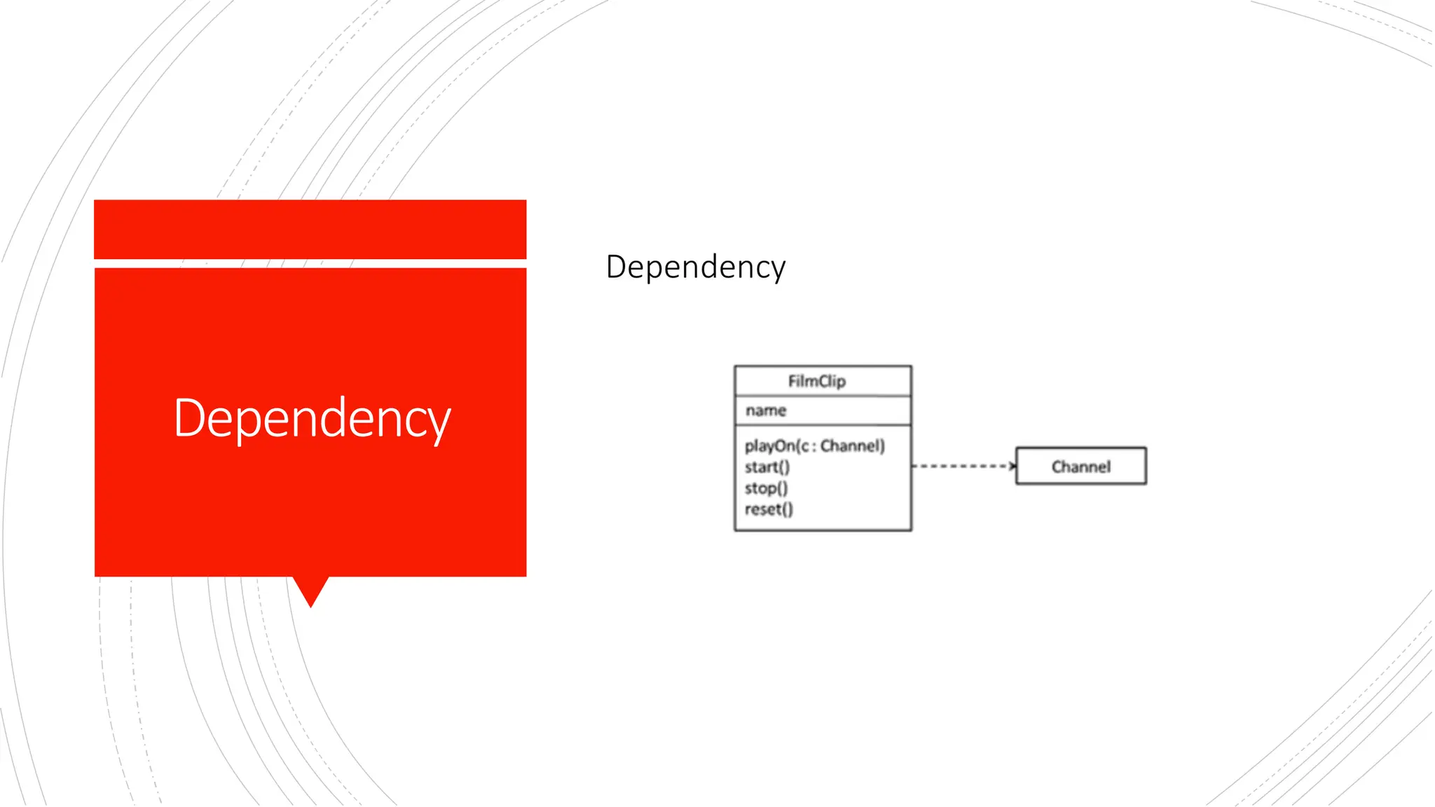
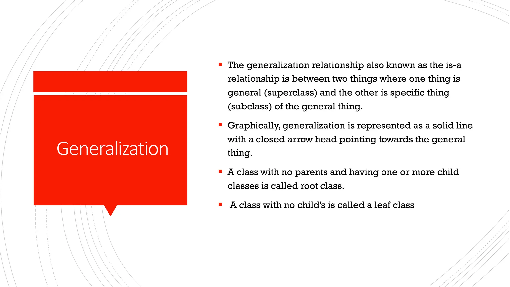
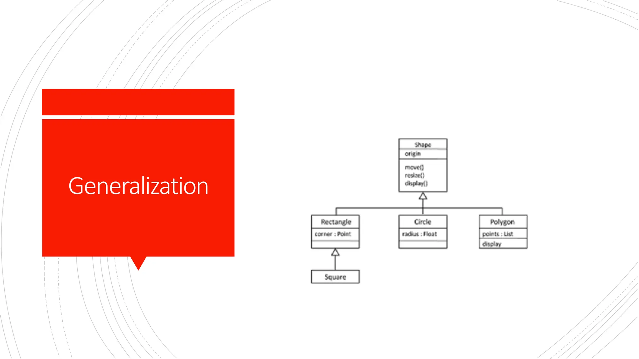
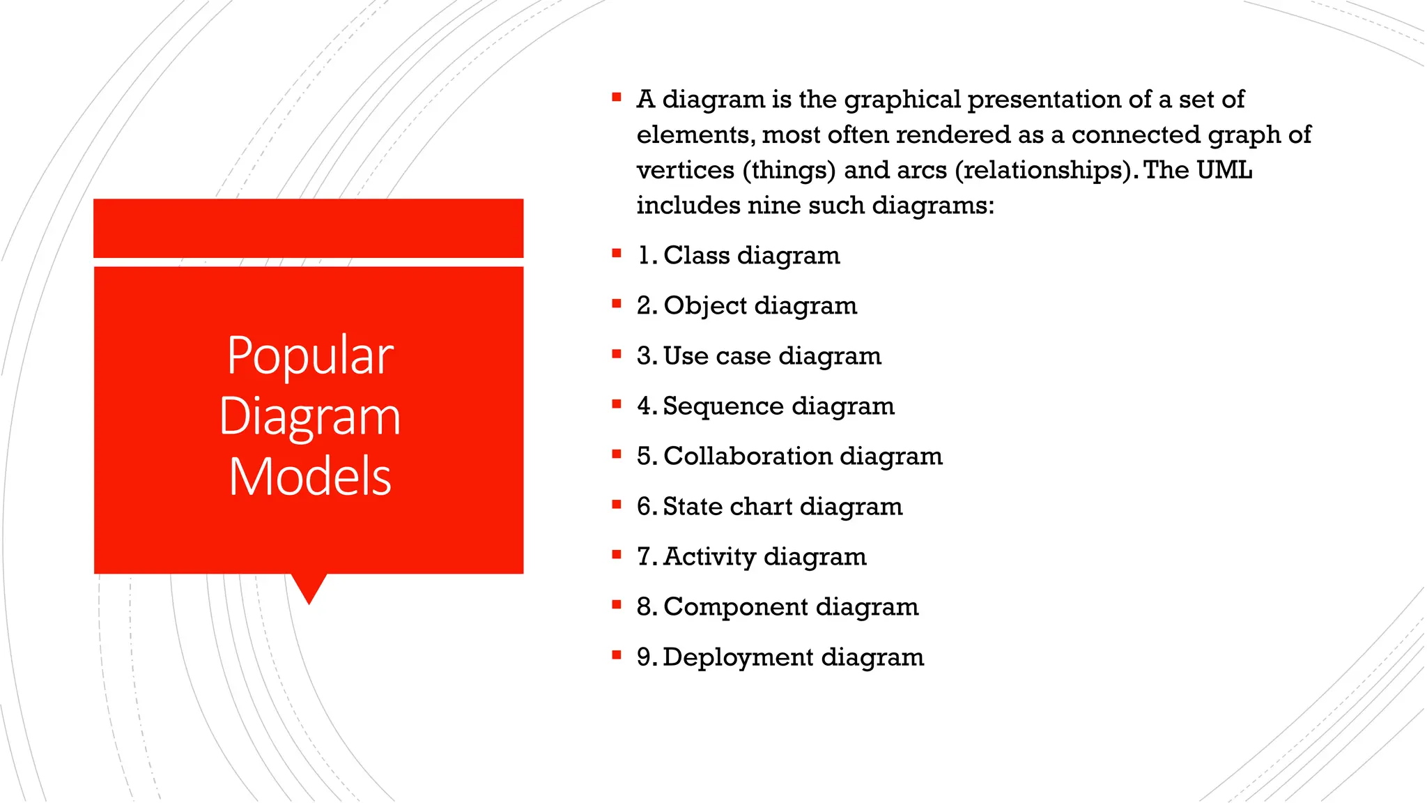
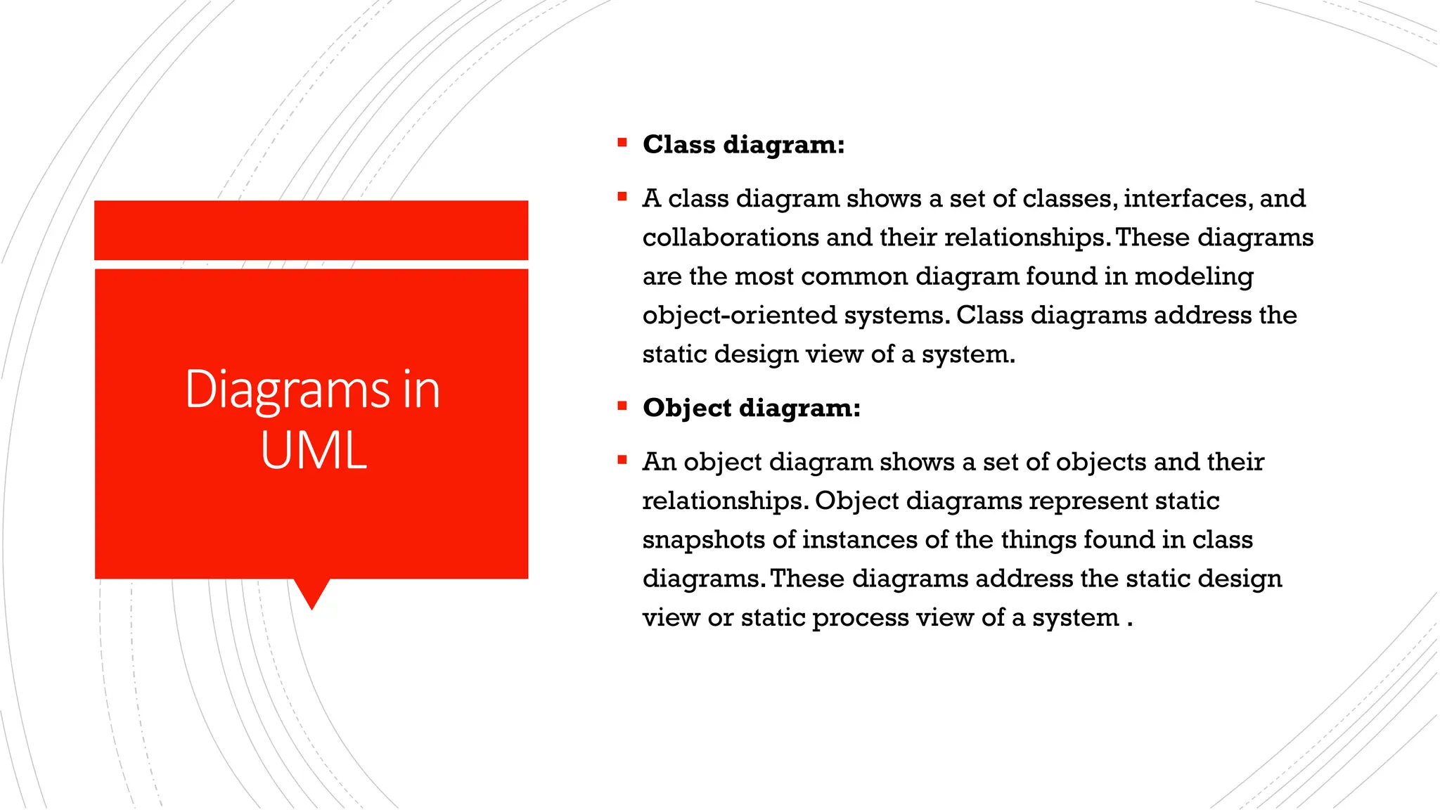
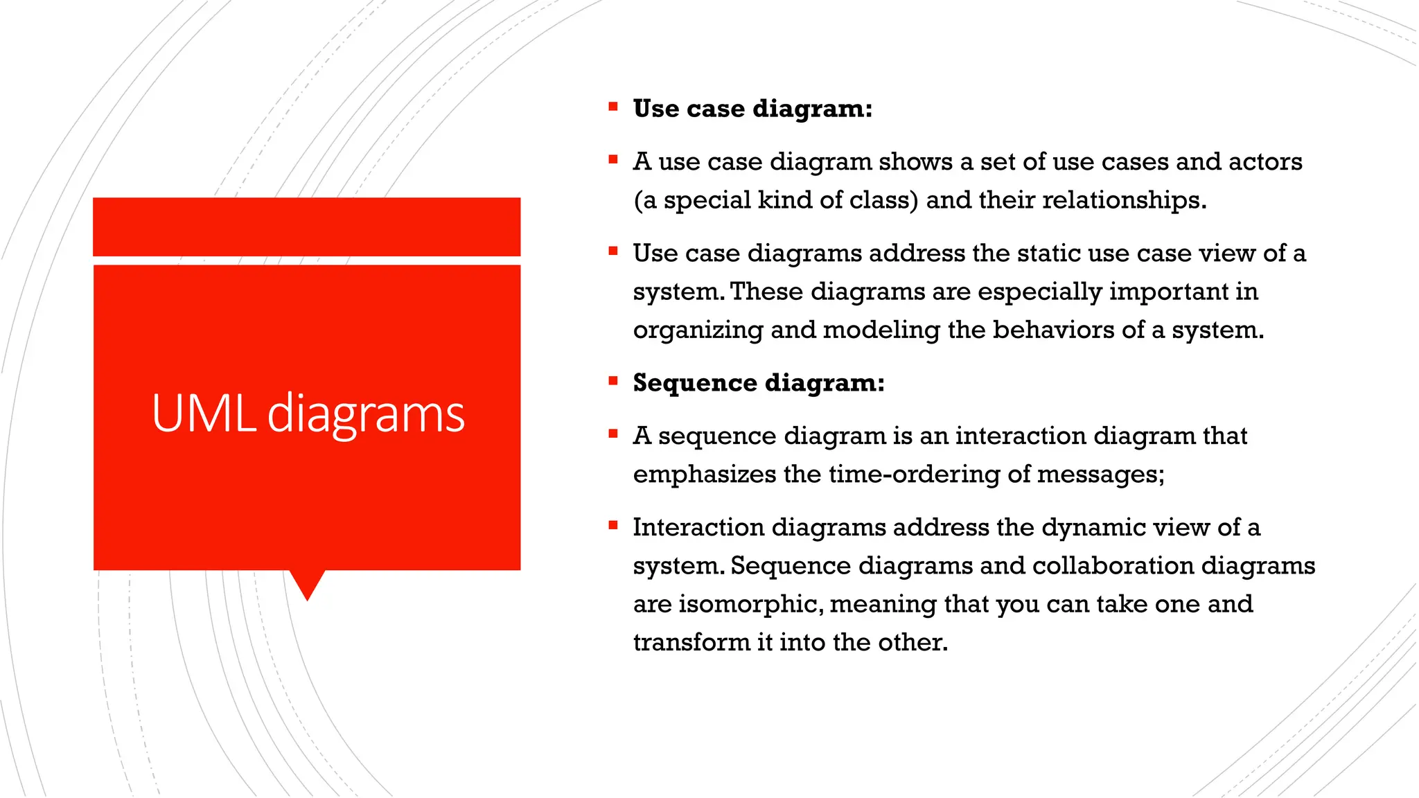
Introduction to UML
OUTLINE ▪ Need for common modeling Language in software Industry ▪ System Modelling ▪ UML Basics ▪ UML things ▪ UML Diagrams
NeedforaUnified Modelling Language ▪ Other industries have languages and notations, which are understood by every member of that particular field. ▪ Mathematicians have a common language. ▪ So do musicians, electronic engineers, and many other disciplines and professions. ▪ Software Engineering has lacked such a notation. ▪ In the past more than 50 software modelling languages were in common use. ▪ Each of them carrying their own notations! ▪ Each language contained syntax peculiar to itself.
Conti’ ▪ In 1996 the Object Management Group (OMG) the most important standardization Group, body for object- oriented software development, called for the specification of a uniform modeling standard to solve issues related to unification.Their aim was to: ❖Use of object-oriented concepts to represent complete systems rather than just one part of the software. ❖Establish of an explicit relationship between modeling concepts and executable program code. ❖Consider scaling factors that are inherent in complex and critical systems. ❖Creation of a modeling language that can be processed by machines but can also be read by human beings.
Conti’ ▪ Today, UML is one of the most widespread graphical object-oriented modeling languages. ▪ UML is simply a language, a notation, a syntax, whatever you want to call it. Crucially, it does not tell you how to develop software. ▪ The first thing to notice about the UML is that there are a lot of different diagrams (models) to get used to. ▪ The reason for this is that it is possible to look at a system from many different viewpoints. ▪ A software development will have many stakeholders playing a part.
System Modeling ▪ A model is a simplification of reality. A model provides the blueprints of a system. ▪ Every system may be described from different aspects using different models, and each model is therefore a semantically closed abstraction of the system. ▪ A model may be structural, emphasizing the organization of the system, or it may be behavioral, emphasizing the dynamics of the system. ▪ We build models so that we can better understand the system we are developing.
Aimsof Modelling ▪ Through modeling, we achieve four aims. ✓1. Models help us to visualize a system as it is or as we want it to be. ✓2. Models permit us to specify the structure or behavior of a system. ✓3. Models give us a template that guides us in constructing a system. ✓4. Models document the decisions we have made.
Principlesof Modelling ▪ The choice of what models to create has a profound influence on how a problem is attacked and how a solution is shaped. ▪ Every model may be expressed at different levels of precision ". Best approach to a given problem results in a best model. If the problem is complex mechanized level of approach & if the problem is simple decent approach is followed. ▪ "The best models are connected to reality.“ The model built should have strong resemblance with the system. ▪ No single model is sufficient. Every nontrivial system is best approached through a small set of nearly independent models.“ If you constructing a building, there is no single set of blueprints that reveal all its details. At the very least, you will need floor plans, elevations, electrical, plans, heating plans, and plumbing plans.
UMLBasics ▪ To understand the UML, we need to form a conceptual model of the language, and this requires learning three major elements: ▪ * Basic Building blocks of the UML ▪ * Rules of the UML ▪ * Common mechanisms in the UML.
BuildingBlocks ▪ UML is composed of three main building blocks, i.e. things, relationships, and diagrams. ▪ Building blocks generate one complete UML model diagram by rotating around several different blocks. ▪ Things ▪ Relationships ▪ Diagrams
ThingsinUML ▪ Things are the abstractions that are first-class citizens in a model; relationships tie these things together. ▪ Anything that is a real-world entity or object is termed as things. ▪ There are four kinds of things in the UML: 1. Structural things 2. Behavioral things 3. Grouping things. 4. Annotational things
Structuralthings ▪ Structural things are the nouns of UML models.These are the mostly static parts of a model, representing elements that are either conceptual or physical. ▪ They display the physical and conceptual components of the system. ▪ They include class, object, interface, node, collaboration, component, and a use case.
Structural things:Class ▪ A class is a description of a set of objects that share the same attributes, operations, relationships, and semantics. ▪ A class implements one or more interfaces. ▪ Graphically, a class is rendered as a rectangle, usually including its name, attributes, and operations
Structural things:Objects ▪ An object is an entity which is used to describe the behavior and functions of a system. ▪ It is an instance of class ▪ The class and object have the same notations. ▪ The only difference is that an object name is always underlined in UML
Behavioral Things ▪ Behavioral things are the dynamic parts of UML models. ▪ These are the verbs of a model, representing behavior over time and space. ▪ In all, there are three primary kinds of behavioral things. ❑Interaction. ❑State machine. ❑Activity.
Behavioral Things: Interaction ▪ First, an interaction is a behavior that comprises a set of messages exchanged among a set of objects or roles within a particular context to accomplish a specific purpose. ▪ The behavior of a society of objects or of an individual operation may be specified with an interaction. ▪ The behavior of a society of objects or of an individual operation may be specified with an interaction. ▪ An interaction involves a number of other elements, including messages, actions, and connectors. ▪ Graphically, a message is rendered as a directed line with arrow head, almost always including the name of its operation.
Behavioral Things:Activity ▪ An activity is a behavior that represents the execution of a process consisting of a sequence of steps, known as activities, which may include decisions, parallel processing, and object flows. ▪ The behavior of a system, business process, or a use case can be specified with an activity. ▪ An activity involves a number of other elements, including actions, control flows, object flows, decisions, and synchronization bars. ▪ Graphically, an activity is rendered using rounded rectangles for actions and arrows for flows, often including decision nodes and swimlanes to show responsibility.
Behavioral Things:State Machine ▪ A state machine is a behavior that specifies the sequences of states an object or an interaction goes through during its lifetime in response to events, together with its responses to those events. ▪ The behavior of an individual class or a collaboration of classes may be specified with a state machine. ▪ A state machine involves a number of other elements, including states, transitions (the flow from state to state), events (things that trigger a transition), and activities (the response to a transition). ▪ Graphically, a state is rendered as a rounded rectangle, usually including its name and its sub states.
Grouping things:Package ▪ A package is a mechanism for organizing model elements into groups, allowing a logical structure to be imposed on the system model. ▪ The structure of large-scale systems or complex models may be specified with packages. ▪ A package involves a number of other elements, including classes, interfaces, components, or even other packages. ▪ Graphically, a package is rendered as a tabbed folder, often containing a list of its elements or visual nesting of diagrams.
Package
Grouping things: Component ▪ A component is a modular, deployable, and replaceable part of a system that encapsulates its contents and exposes a set of interfaces. ▪ The structure of software systems and how code elements are packaged for deployment may be specified with components. ▪ A component involves a number of other elements, including interfaces, classes, ports, and dependencies. ▪ Graphically, a component is rendered as a rectangle with two smaller rectangles (lollipops or tabs) on its side, often showing its provided and required interfaces.
Component
Grouping things: Subsystem ▪ A subsystem is a specialized component that represents a self-contained unit of functionality within a larger system, often used to partition a system into manageable parts. ▪ The architecture of large systems may be specified with subsystems. ▪ A subsystem involves a number of other elements, including components, interfaces, and packages. ▪ Graphically, a subsystem is rendered as a component with the stereotype «subsystem», and it may contain internal structure or references to other elements.
Annotation things:Note ▪ An annotation is a mechanism used to attach descriptive comments or explanatory notes to UML model elements, enhancing the readability and understanding of the diagram. ▪ These are the comments you may apply to describe, illuminate, and remark about any element in a model. ▪ There is one primary kind of anotational thing, called a note. ▪ A note is simply a symbol for rendering constraints and comments attached to an element or a collection of elements. ▪ Graphically, a note is rendered as a rectangle with a dog-eared corner, together with a textual or graphical comment.
Note:
Relationships ▪ When we model the system, we first identify the key components.These components or elements will not remain alone. ▪ They collaborate.This means they are connected with others in some way. It is called the relationship of things. ▪ The relationship allows you to show on a model how two or more things relate to each other. ▪ The relationship in UML will enable you to capture meaningful connections between things. ▪ It shows how each element is associated with each other and how this association describes the functionality of an application.
Relationship: Association ▪ An association is a structural relationship which connects one thing with another. ▪ Simple link between things. ▪ Given an association between two things, we can navigate from one thing to the other thing and vice versa. ▪ It is also common for a thing to have a self association. ▪ Multiplicity is introduced that tells us how many objects of a particular element are associated. ▪ It can be denoted as simple dotted or solid line graphically
Graphic representation
Relationship: Dependency ▪ A dependency is a using relationship. In this relationship one thing depends on the other thing. ▪ It is a semantic relationship in which a change to one element (the independent one) may affect the semantics of the other element (the dependent one). ▪ Graphically, a dependency is rendered as a dashed line, possibly directed, and occasionally including a label.
Dependency
Generalization ▪ The generalization relationship also known as the is-a relationship is between two things where one thing is general (superclass) and the other is specific thing (subclass) of the general thing. ▪ Graphically, generalization is represented as a solid line with a closed arrow head pointing towards the general thing. ▪ A class with no parents and having one or more child classes is called root class. ▪ A class with no child’s is called a leaf class
Generalization
Other relationshipsin UMLto read. ▪ Realization ▪ Composition ▪ Aggregation
Popular Diagram Models ▪ A diagram is the graphical presentation of a set of elements, most often rendered as a connected graph of vertices (things) and arcs (relationships).The UML includes nine such diagrams: ▪ 1. Class diagram ▪ 2. Object diagram ▪ 3. Use case diagram ▪ 4. Sequence diagram ▪ 5. Collaboration diagram ▪ 6. State chart diagram ▪ 7. Activity diagram ▪ 8. Component diagram ▪ 9. Deployment diagram
Diagramsin UML ▪ Class diagram: ▪ A class diagram shows a set of classes, interfaces, and collaborations and their relationships.These diagrams are the most common diagram found in modeling object-oriented systems. Class diagrams address the static design view of a system. ▪ Object diagram: ▪ An object diagram shows a set of objects and their relationships. Object diagrams represent static snapshots of instances of the things found in class diagrams.These diagrams address the static design view or static process view of a system .
UMLdiagrams ▪ Use case diagram: ▪ A use case diagram shows a set of use cases and actors (a special kind of class) and their relationships. ▪ Use case diagrams address the static use case view of a system.These diagrams are especially important in organizing and modeling the behaviors of a system. ▪ Sequence diagram: ▪ A sequence diagram is an interaction diagram that emphasizes the time-ordering of messages; ▪ Interaction diagrams address the dynamic view of a system. Sequence diagrams and collaboration diagrams are isomorphic, meaning that you can take one and transform it into the other.
Reading assignment, Useothersources beyond thetwo booksshared ▪ On Diagrams read about deployment, collaboration and component. ▪ UML rules ▪ UML Mechanisms

Object oriented analysis and Design: UML Basics.pdf

  • 1.
  • 2.
    OUTLINE ▪ Need forcommon modeling Language in software Industry ▪ System Modelling ▪ UML Basics ▪ UML things ▪ UML Diagrams
  • 3.
    NeedforaUnified Modelling Language ▪ Other industrieshave languages and notations, which are understood by every member of that particular field. ▪ Mathematicians have a common language. ▪ So do musicians, electronic engineers, and many other disciplines and professions. ▪ Software Engineering has lacked such a notation. ▪ In the past more than 50 software modelling languages were in common use. ▪ Each of them carrying their own notations! ▪ Each language contained syntax peculiar to itself.
  • 4.
    Conti’ ▪ In 1996the Object Management Group (OMG) the most important standardization Group, body for object- oriented software development, called for the specification of a uniform modeling standard to solve issues related to unification.Their aim was to: ❖Use of object-oriented concepts to represent complete systems rather than just one part of the software. ❖Establish of an explicit relationship between modeling concepts and executable program code. ❖Consider scaling factors that are inherent in complex and critical systems. ❖Creation of a modeling language that can be processed by machines but can also be read by human beings.
  • 5.
    Conti’ ▪ Today, UMLis one of the most widespread graphical object-oriented modeling languages. ▪ UML is simply a language, a notation, a syntax, whatever you want to call it. Crucially, it does not tell you how to develop software. ▪ The first thing to notice about the UML is that there are a lot of different diagrams (models) to get used to. ▪ The reason for this is that it is possible to look at a system from many different viewpoints. ▪ A software development will have many stakeholders playing a part.
  • 6.
    System Modeling ▪ A modelis a simplification of reality. A model provides the blueprints of a system. ▪ Every system may be described from different aspects using different models, and each model is therefore a semantically closed abstraction of the system. ▪ A model may be structural, emphasizing the organization of the system, or it may be behavioral, emphasizing the dynamics of the system. ▪ We build models so that we can better understand the system we are developing.
  • 7.
    Aimsof Modelling ▪ Through modeling,we achieve four aims. ✓1. Models help us to visualize a system as it is or as we want it to be. ✓2. Models permit us to specify the structure or behavior of a system. ✓3. Models give us a template that guides us in constructing a system. ✓4. Models document the decisions we have made.
  • 8.
    Principlesof Modelling ▪ The choiceof what models to create has a profound influence on how a problem is attacked and how a solution is shaped. ▪ Every model may be expressed at different levels of precision ". Best approach to a given problem results in a best model. If the problem is complex mechanized level of approach & if the problem is simple decent approach is followed. ▪ "The best models are connected to reality.“ The model built should have strong resemblance with the system. ▪ No single model is sufficient. Every nontrivial system is best approached through a small set of nearly independent models.“ If you constructing a building, there is no single set of blueprints that reveal all its details. At the very least, you will need floor plans, elevations, electrical, plans, heating plans, and plumbing plans.
  • 9.
    UMLBasics ▪ To understandthe UML, we need to form a conceptual model of the language, and this requires learning three major elements: ▪ * Basic Building blocks of the UML ▪ * Rules of the UML ▪ * Common mechanisms in the UML.
  • 10.
    BuildingBlocks ▪ UML iscomposed of three main building blocks, i.e. things, relationships, and diagrams. ▪ Building blocks generate one complete UML model diagram by rotating around several different blocks. ▪ Things ▪ Relationships ▪ Diagrams
  • 11.
    ThingsinUML ▪ Things arethe abstractions that are first-class citizens in a model; relationships tie these things together. ▪ Anything that is a real-world entity or object is termed as things. ▪ There are four kinds of things in the UML: 1. Structural things 2. Behavioral things 3. Grouping things. 4. Annotational things
  • 12.
    Structuralthings ▪ Structural thingsare the nouns of UML models.These are the mostly static parts of a model, representing elements that are either conceptual or physical. ▪ They display the physical and conceptual components of the system. ▪ They include class, object, interface, node, collaboration, component, and a use case.
  • 13.
    Structural things:Class ▪ A classis a description of a set of objects that share the same attributes, operations, relationships, and semantics. ▪ A class implements one or more interfaces. ▪ Graphically, a class is rendered as a rectangle, usually including its name, attributes, and operations
  • 14.
    Structural things:Objects ▪ An objectis an entity which is used to describe the behavior and functions of a system. ▪ It is an instance of class ▪ The class and object have the same notations. ▪ The only difference is that an object name is always underlined in UML
  • 15.
    Behavioral Things ▪ Behavioral thingsare the dynamic parts of UML models. ▪ These are the verbs of a model, representing behavior over time and space. ▪ In all, there are three primary kinds of behavioral things. ❑Interaction. ❑State machine. ❑Activity.
  • 16.
    Behavioral Things: Interaction ▪ First, aninteraction is a behavior that comprises a set of messages exchanged among a set of objects or roles within a particular context to accomplish a specific purpose. ▪ The behavior of a society of objects or of an individual operation may be specified with an interaction. ▪ The behavior of a society of objects or of an individual operation may be specified with an interaction. ▪ An interaction involves a number of other elements, including messages, actions, and connectors. ▪ Graphically, a message is rendered as a directed line with arrow head, almost always including the name of its operation.
  • 17.
    Behavioral Things:Activity ▪ An activityis a behavior that represents the execution of a process consisting of a sequence of steps, known as activities, which may include decisions, parallel processing, and object flows. ▪ The behavior of a system, business process, or a use case can be specified with an activity. ▪ An activity involves a number of other elements, including actions, control flows, object flows, decisions, and synchronization bars. ▪ Graphically, an activity is rendered using rounded rectangles for actions and arrows for flows, often including decision nodes and swimlanes to show responsibility.
  • 18.
    Behavioral Things:State Machine ▪ A statemachine is a behavior that specifies the sequences of states an object or an interaction goes through during its lifetime in response to events, together with its responses to those events. ▪ The behavior of an individual class or a collaboration of classes may be specified with a state machine. ▪ A state machine involves a number of other elements, including states, transitions (the flow from state to state), events (things that trigger a transition), and activities (the response to a transition). ▪ Graphically, a state is rendered as a rounded rectangle, usually including its name and its sub states.
  • 19.
    Grouping things:Package ▪ A packageis a mechanism for organizing model elements into groups, allowing a logical structure to be imposed on the system model. ▪ The structure of large-scale systems or complex models may be specified with packages. ▪ A package involves a number of other elements, including classes, interfaces, components, or even other packages. ▪ Graphically, a package is rendered as a tabbed folder, often containing a list of its elements or visual nesting of diagrams.
  • 20.
  • 21.
    Grouping things: Component ▪ A componentis a modular, deployable, and replaceable part of a system that encapsulates its contents and exposes a set of interfaces. ▪ The structure of software systems and how code elements are packaged for deployment may be specified with components. ▪ A component involves a number of other elements, including interfaces, classes, ports, and dependencies. ▪ Graphically, a component is rendered as a rectangle with two smaller rectangles (lollipops or tabs) on its side, often showing its provided and required interfaces.
  • 22.
  • 23.
    Grouping things: Subsystem ▪ A subsystemis a specialized component that represents a self-contained unit of functionality within a larger system, often used to partition a system into manageable parts. ▪ The architecture of large systems may be specified with subsystems. ▪ A subsystem involves a number of other elements, including components, interfaces, and packages. ▪ Graphically, a subsystem is rendered as a component with the stereotype «subsystem», and it may contain internal structure or references to other elements.
  • 24.
    Annotation things:Note ▪ An annotationis a mechanism used to attach descriptive comments or explanatory notes to UML model elements, enhancing the readability and understanding of the diagram. ▪ These are the comments you may apply to describe, illuminate, and remark about any element in a model. ▪ There is one primary kind of anotational thing, called a note. ▪ A note is simply a symbol for rendering constraints and comments attached to an element or a collection of elements. ▪ Graphically, a note is rendered as a rectangle with a dog-eared corner, together with a textual or graphical comment.
  • 25.
  • 26.
    Relationships ▪ When wemodel the system, we first identify the key components.These components or elements will not remain alone. ▪ They collaborate.This means they are connected with others in some way. It is called the relationship of things. ▪ The relationship allows you to show on a model how two or more things relate to each other. ▪ The relationship in UML will enable you to capture meaningful connections between things. ▪ It shows how each element is associated with each other and how this association describes the functionality of an application.
  • 27.
    Relationship: Association ▪ An associationis a structural relationship which connects one thing with another. ▪ Simple link between things. ▪ Given an association between two things, we can navigate from one thing to the other thing and vice versa. ▪ It is also common for a thing to have a self association. ▪ Multiplicity is introduced that tells us how many objects of a particular element are associated. ▪ It can be denoted as simple dotted or solid line graphically
  • 28.
  • 29.
    Relationship: Dependency ▪ A dependencyis a using relationship. In this relationship one thing depends on the other thing. ▪ It is a semantic relationship in which a change to one element (the independent one) may affect the semantics of the other element (the dependent one). ▪ Graphically, a dependency is rendered as a dashed line, possibly directed, and occasionally including a label.
  • 30.
  • 31.
    Generalization ▪ The generalizationrelationship also known as the is-a relationship is between two things where one thing is general (superclass) and the other is specific thing (subclass) of the general thing. ▪ Graphically, generalization is represented as a solid line with a closed arrow head pointing towards the general thing. ▪ A class with no parents and having one or more child classes is called root class. ▪ A class with no child’s is called a leaf class
  • 32.
  • 33.
  • 34.
    Popular Diagram Models ▪ A diagramis the graphical presentation of a set of elements, most often rendered as a connected graph of vertices (things) and arcs (relationships).The UML includes nine such diagrams: ▪ 1. Class diagram ▪ 2. Object diagram ▪ 3. Use case diagram ▪ 4. Sequence diagram ▪ 5. Collaboration diagram ▪ 6. State chart diagram ▪ 7. Activity diagram ▪ 8. Component diagram ▪ 9. Deployment diagram
  • 35.
    Diagramsin UML ▪ Class diagram: ▪A class diagram shows a set of classes, interfaces, and collaborations and their relationships.These diagrams are the most common diagram found in modeling object-oriented systems. Class diagrams address the static design view of a system. ▪ Object diagram: ▪ An object diagram shows a set of objects and their relationships. Object diagrams represent static snapshots of instances of the things found in class diagrams.These diagrams address the static design view or static process view of a system .
  • 36.
    UMLdiagrams ▪ Use casediagram: ▪ A use case diagram shows a set of use cases and actors (a special kind of class) and their relationships. ▪ Use case diagrams address the static use case view of a system.These diagrams are especially important in organizing and modeling the behaviors of a system. ▪ Sequence diagram: ▪ A sequence diagram is an interaction diagram that emphasizes the time-ordering of messages; ▪ Interaction diagrams address the dynamic view of a system. Sequence diagrams and collaboration diagrams are isomorphic, meaning that you can take one and transform it into the other.
  • 37.
    Reading assignment, Useothersources beyond thetwo booksshared ▪ OnDiagrams read about deployment, collaboration and component. ▪ UML rules ▪ UML Mechanisms