Downloaded 2,651 times


![while(!col2); return key; } if(!col3) { key = k+2; while(!col3); return key; } j++; } k+=3; keyport |= 0x80>>i; delayms(10); } return FALSE; } unsigned char translate(unsigned char keyval) { if(keyval<10) return keyval+' else if(keyval==10) return 'x'; else if(keyval==11) return '0'; else if(keyval==12) return 'e'; } LCD program: #include "lcd.h" #include "delay.h" #include <REG2051.H> unsigned char codelockicon[]={0xe, 0xa, 0x1f, 0x1f, 0x1b, 0x1b, 0xe, 0x0}; unsigned char codeunlockicon[]={0xe, 0x2, 0x1f, 0x1f, 0x1b, 0x1b, 0xe, 0x0}; unsigned char codeex[]={0x1f, 0x1b, 0x1b, 0x1b, 0x1b, 0x1f, 0x1b, 0x1f}; unsigned char codeok[]={0x0, 0x1, 0x3, 0x16, 0x1c, 0x8, 0x0, 0x0}; void lcd_reset() { lcd_port= 0xFF; delayms(20); lcd_port= 0x03+LCD_EN; lcd_port = 0x03;](https://image.slidesharecdn.com/passwordbaseddoorlocksystemusing8051microcontrollerfinalreport-150418010421-conversion-gate02/75/Password-based-door-lock-system-using-8051-microcontroller-final-report-11-2048.jpg)
![delayms(10); lcd_port= 0x03+LCD_EN; lcd_port= 0x03; delayms(1); lcd_port= 0x03+LCD_EN; lcd_port= 0x03; delayms(1); lcd_port= 0x02+LCD_EN; lcd_port= 0x02; delayms(1); } void lcd_init () { unsigned char i; lcd_reset(); lcd_cmd(LCD_SETFUNCTION);// 4-bit mode - 1 line - 5x7 font. lcd_cmd(LCD_SETVISIBLE+0x04); // Display no cursor - no blink. lcd_cmd(LCD_SETMODE+0x02); // Automatic Increment - No Display shift. lcd_cmd(LCD_SETCGADDR); for(i=0;i<8;i++) lcd_data(lockicon[i]); 27](https://image.slidesharecdn.com/passwordbaseddoorlocksystemusing8051microcontrollerfinalreport-150418010421-conversion-gate02/75/Password-based-door-lock-system-using-8051-microcontroller-final-report-12-2048.jpg)
![for(i=0;i<8;i++) lcd_data(unlockicon[i]); for(i=0;i<8;i++) lcd_data(ex[i]); for(i=0;i<8;i++) lcd_data(for(i=0;i<8;i++) lcd_data(unlockicon[i]); for(i=0;i<8;i++) lcd_data(ex[i]); for(i=0;i<8;i++) lcd_data(ok[i]); lcd_cmd(LCD_SETDDADDR); // Address DDRAM with 0 offset 80h. } void lcd_cmd (char cmd) { lcd_port= ((cmd >> 4) & 0x0F)|LCD_EN; lcd_port= ((cmd >> 4) & 0x0F); lcd_port= (cmd & 0x0F)|LCD_EN; lcd_port= (cmd & 0x0F); delayus(200); delayus(200); } void lcd_data (unsigned char dat) { lcd_port= (((dat >> 4) & 0x0F)|LCD_EN|LCD_RS); lcd_port= (((dat >> 4) & 0x0F)|LCD_RS); lcd_port= ((dat & 0x0F)|LCD_EN|LCD_RS); lcd_port= ((dat & 0x0F)|LCD_RS); delayus(200); delayus(200); } void lcd_str(unsigned char *str) { while(*str){ lcd_data(*str++); } } Lock program: #include "keypad.h" #include "lcd.h" #include "delay.h" #include "lock.h" unsigned char codemasterlock[10]="1234567890", defaultulock[5]="54321"; unsigned char userlock[5], input[10]; extern bit newlock; bit check(unsigned char *first, unsigned char *second, unsigned char len)](https://image.slidesharecdn.com/passwordbaseddoorlocksystemusing8051microcontrollerfinalreport-150418010421-conversion-gate02/75/Password-based-door-lock-system-using-8051-microcontroller-final-report-13-2048.jpg)
![while(1){ while(!(key=getkey())); key = translate(key); input[i]=key; if(key=='x'){ if(i==0) return EXIT; i--; lcd_cmd(0xC2+i); lcd_data(' '); lcd_cmd(0xC2+i); } else if(key=='e') { return TRUE; } else{ i++; if(i>max){ lcd_cmd(LCD_CLS); lcd_data(EX); lcd_str(" Codetoo Long..."); delayms(250); delayms(250); delayms(250); delayms(250); return RETRY; } lcd_data('*'); } } } void store_code(){ unsigned char i; for(i=0;i<5;i++) userlock[i]=input[i]; } Main program: #include "lcd.h" #include "keypad.h" #include "lock.h" #include "delay.h"extern unsigned char input[10], userlock[5]; extern unsigned char codedefaultulock[5],masterlock[10]; bit newlock=FALSE; unsigned char retrycount=3; void main(){ unsigned char status,i=0;](https://image.slidesharecdn.com/passwordbaseddoorlocksystemusing8051microcontrollerfinalreport-150418010421-conversion-gate02/75/Password-based-door-lock-system-using-8051-microcontroller-final-report-15-2048.jpg)


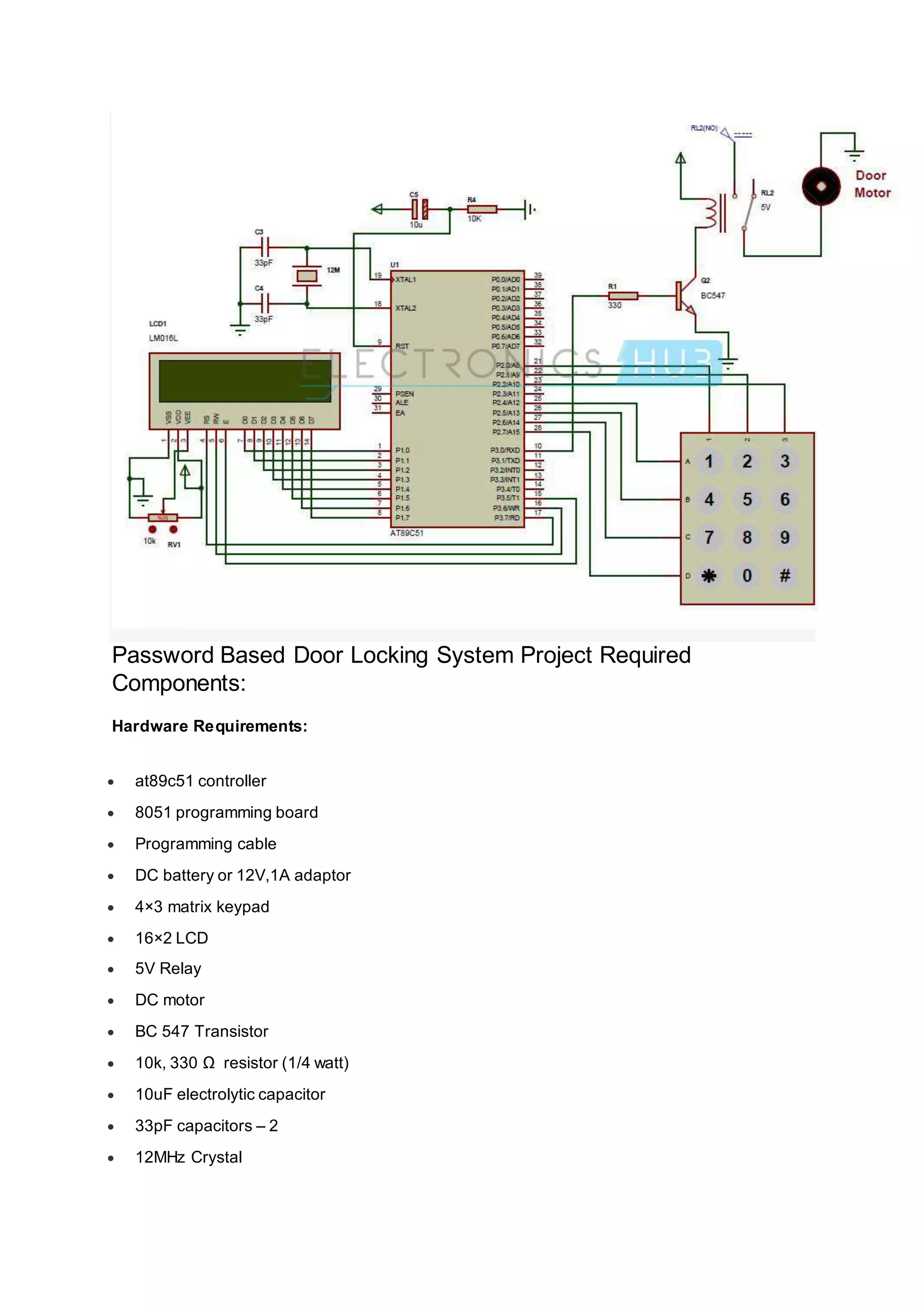
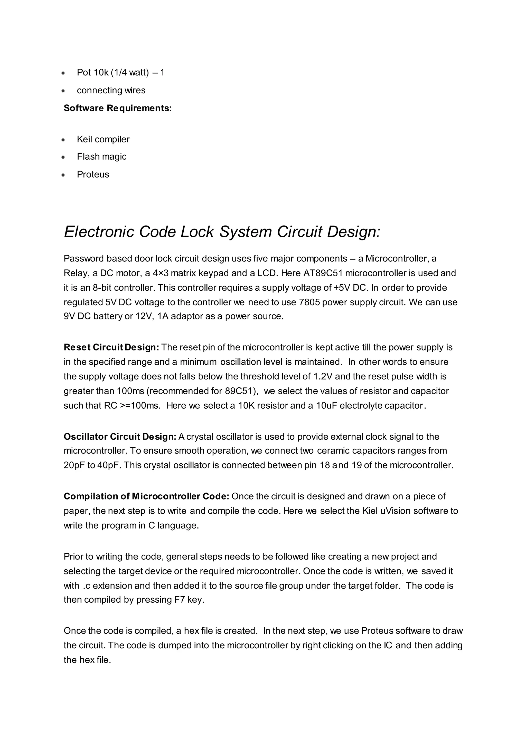
This document describes a password-based door lock system using an 8051 microcontroller. The system uses a keypad to enter a password, which is compared to a predefined password stored in the microcontroller's memory. If the entered password matches, the microcontroller will open the door by activating a motor. If an incorrect password is entered more than three times, an alarm will sound. The system is designed to only grant access to those who know the correct password, while denying access and potentially alerting others for incorrect password attempts.