


Introduction
Connect the Microchip RN2483 with an the ESP8266 based NodeMCU devkit board. Code in arduino, import the necessary libraries, set the needed settings and implement your own LoRa + WiFi enabled Thing.
Connecting the parts
For a very basic setup, you’ll be needing a proto PCB (or a protoboard if you don’t wan’t to solder everything just yet), NodeMCU 1.0 devkit, RN2483 chip, some patch wires, solid core wire to act as an antenna, and soldering wire.
The NodeMCU has a bigger form factor than the RN2483 chip, so it’s possible even to solder them tightly together or one under the other by using some header pins aside.
The connection between the two goes like this:
RN2483 TX (6) <-> NodeMCU D6 RN2483 RX (7) <-> NodeMCU D5 RN2483 VDD (12 or 34) <-> NodeMCU 3.3V RN2483 GND (20 or 33 …) <-> NodeMCU GND RN2483 RESET (32) <-> NodeMCU D7 RN2483 RFH (23) <-> Antenna or 8.6cm solid core wire
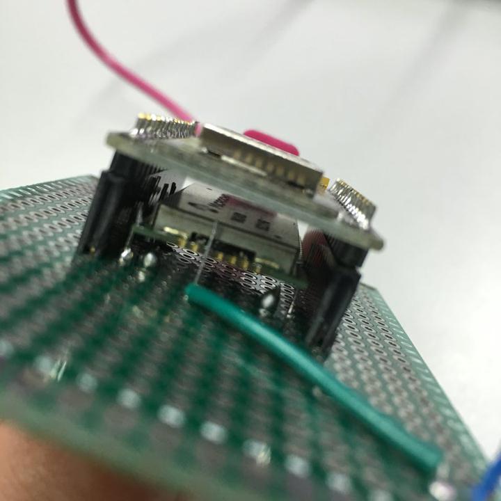
The RN2483 is with a smaller form factor than the NodeMCU and it can perfectly fit underneath it. This is what I did:


Code
Before you go off coding, first do some preparations:
– get the latest Arduino IDE
– install the nodemcu devkit driver
– install the esp8266 board in the Boards manager (or update to the latest)
– install the RN2483 library
– install the ESPSoftwareSerial library
The code I’m using is a modification of this nice tutorial done by jpmeiers.
#include <rn2483.h> #include <SoftwareSerial.h> #define RST D7 SoftwareSerial mySerial(D6, D5); // RX, TX //create an instance of the rn2483 library, //giving the software UART as stream to use, //and using LoRa WAN rn2483 myLora(mySerial); // the setup routine runs once when you press reset: void setup() { // Open serial communications and wait for port to open: Serial.begin(57600); mySerial.begin(9600); Serial.println("Startup"); //reset rn2483 pinMode(RST, OUTPUT); digitalWrite(RST, LOW); delay(500); digitalWrite(RST, HIGH); //initialise the rn2483 module myLora.autobaud(); //print out the HWEUI so that we can register it via ttnctl Serial.println("When using OTAA, register this DevEUI: "); Serial.println(myLora.hweui()); Serial.println("RN2483 version number:"); Serial.println(myLora.sysver()); //OTAA: init(String AppEUI, String AppKey); myLora.init("<Insert you app EUI key here>", "<insert your default app key here>"); delay(2000); } // the loop routine runs over and over again forever: void loop() { //Do your stuff here //Measure things if you're working with a sensor //and pack them into an output string String toSend = "DataHere"; Serial.println("TXing: " + toSend); myLora.txUncnf(toSend ); //send the data Serial.println("TXed."); delay(60000); //Send every minute (maybe you need to tune this) }*) this is the bare minimum you need in order to start things working. I got it by modifying the original code and removing the other parts afterwards, so let me know if something is not right.
When you got all packed, choose NodeMCU to be your current board, fire the serial monitor, set it to 57600 baud rate, and flash the code to the device. If everything is fine, you should see nice messages in the serial log, and by refreshing the app page on TTN, you should see your device registered and messages arriving every minute.
Extend and pack
The final product I made with all this is a Dust, Temperature and humidity TTN sensor node. You can do that by combining DHT22 (tutorial here) and sharp dust sensor (arduino tutorial here). However, the code still looks a bit shaky, and the dust sensor might need some extra work and/or calibration, so I don’t dare yet to publish it.

And as a final touch, I designed a custom enclosure in OpenSCAD (a mix of this design by b2vn) and I 3D printed it. I just made it longer and wider, and put holes for the DHT and the dust sensor opening, to have air circulating.
The final result:
