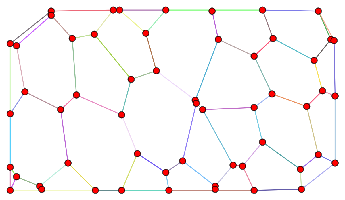
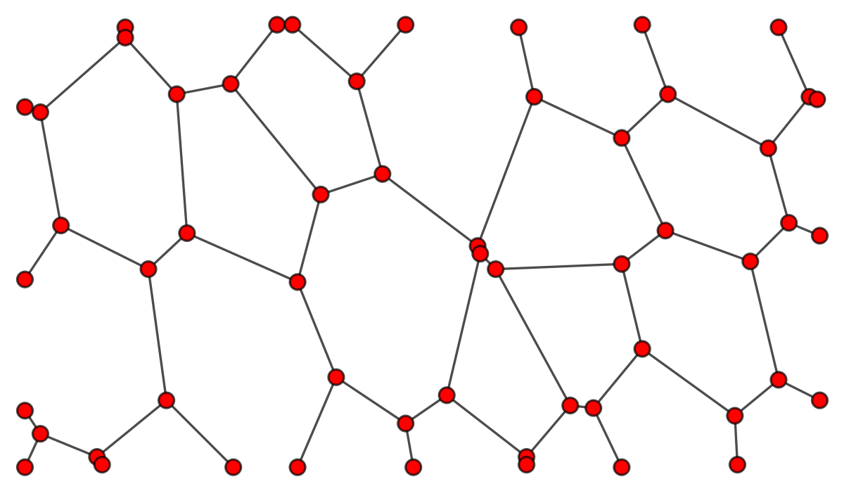
The graph g in the example:
With direct application of ConvexHullMesh and usage of the generated Lines there are missing edges at the boundary. The graph below colors edges randomly but as we see there are many supposed edges at the boundary that are actually the same edge as they have the same color. They are simply long edges that traverse the vertices due to the imposed geometry for the graph.
With the codecodes below all edges are included depending on the definition one takes. Note
Definition A
The boundary is the set of degree 1 vertices that are not encircled by other vertices in the geometrical graph embedding."
In other words they are the outer vertices that randomly coloringare of degree 1. This definition works nicely in the edges a few times, accidental same color adjacent edgesexample above as most of the outer vertices are removedof degree 1.
Definition B
The boundary is the set of vertices that belong to the convex hull.
Note that this might not be your preferred definition given that you gave a non convex example. In particular some of the outer degree 1 vertices will not be included in the boundary.
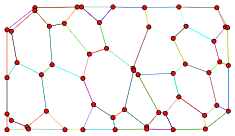
Definition A : Focus on the degree 1 vertices
The image below is generated from the code in the last section.
Note that randomly coloring the edges a few times, accidental same color adjacent edges are removed.
Definition B: focus on the convex hull
The change is minor in this case as only the blue vertices are not on the convex hull. The change would be more significant for a "less convex" graph:
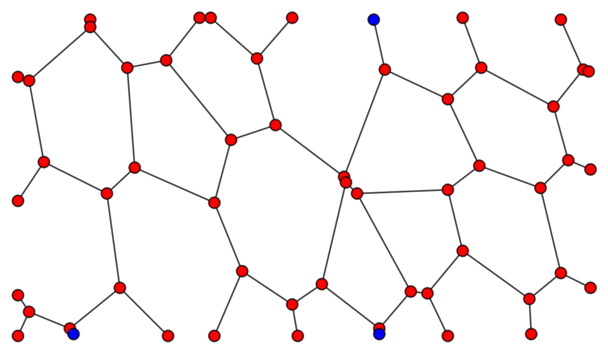
Nevertheless these are the edges for this definition:

Issue with application of ConvexHull
Issue with direct application of ConvexHull
Solution to OP's question
Possible solution
TL;DR: Extract degree 1 vertices at the boundary either by their degree or whether they belong to the convex hull (may lead to different results depending on the graph), use FindCurvePath and PathGraph to connect them and then add them to the original graph with a graph position to geometrical postion mapping.
Method 1: Exploit the vertex degree of the vertices at the boundary.
The vertices atAll of the boundary are all degree one1 vertices in the example provided are "outer vertices" hence we shall not impose the constraint that the vertex should not be encircled by others. TheyFor another graph one might have to add the no encircling constraint.
Degree 1 vertices can be extracted using:
KVertexConnectedGraphQ[completed…graph, 2]
(* True *)
Method 2: Extract points from the boundary of the convex hull.
Note : Mainly only the code for boundary…vertices⎵positions is changed, the rest is copy pasted for those that did not read method 1 and I will indicate when the rest is copy pasted.
The boundary of the convex hull as a list lines:
lines = ConvexHullMesh[GraphEmbedding[g]] // MeshPrimitives[#, 1] &;
Geometric positions of vertices in the graph can be found using the rule:
VertexPos = Thread[VertexList[g] -> GraphEmbedding[g]]
A function that checks whether a point belongs to the boundary:
boundaryPoint[point_] := AnyTrue[lines, RegionMember[#, point] &];
Select the positions of boundary vertices in the graph embedding :
boundary…vertices⎵positions = Select[VertexList[g] /. VertexPos, boundaryPoint]
The following is identical to method 1 and so has been copy pasted for convenience:
One may order these vertices along a path using FindCurvePath
path…ordering = FindCurvePath[boundary…vertices⎵positions]; path = boundary…vertices⎵positions[[path…ordering[[1]]]]
Then one may construct edges from those ordered points using PathGraph and EdgeList. Note that we first had to order the edges before using PathGraph.
path⎵edges = path // PathGraph // EdgeList;
Those are written as spatial points we have to convert them back to vertex positions by inverting VertexPos above. We then add those edges to the original graph:
completed…graph = EdgeAdd[g, path⎵edges /. Reverse /@ VertexPos]
We can check the result with:
HighlightGraph[completed…graph, Style[#, RandomColor[]] & /@ EdgeList@completed…graph]
Note: some edges at the boundary might randomly have a similar color, evaluate the code again to change colors and check that the edges no longer have the same color.