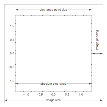
As per the comment section of the OP I assume that the image padding is a constant number of printer points, though it is not necessarily known. I use the rasterize trick to obtain the size of the plotting range in printer points:
printerPointsPlotRange = (#[[2]] - #[[1]] &)@ (Rasterize[Show[#, Epilog -> {Annotation[Rectangle[Scaled[{0, 0}], Scaled[{1, 1}]], "Two", "Region"]}], "Regions"][[-1, 2]]) &
Similarly, my own implementation of ImageDimensions. It gives the size of the rectangle defined by Rectangle[ImageScaled[{0,0}],ImageScaled[{1,1}]] in printer points, which does not always match ImageDimensions if ImageSize and AspectRatio lead to conflicting results:
realImageDimensions = (#[[2]] - #[[1]] &)@ (Rasterize[Show[#, Epilog -> {Annotation[Rectangle[ImageScaled[{0, 0}], ImageScaled[{1, 1}]], "Two", "Region"]}], "Regions"][[-1, 2]]) &
I implement a modified version of PlotRange to account for PlotRangePadding.
realPlotRange = Module[ {padding = Total /@ (Options[#, PlotRangePadding][[-1, 2]] /. None -> 0), baserange = (#[[2]] - #[[1]] &) /@ PlotRange[#], range}, range = (baserange + padding) /. {a_ Scaled[b_] :> Scaled[a b], Scaled[a_] + Scaled[b_] :> Scaled[a + b]} /. {a_ + Scaled[b_] :> a/(1 - b)}; range] &
It appears to fail for mixed specifications, such as {{1,Scaled[.1]},{Scaled[.02],Scaled[.02]}}. However if the left and right paddings are both given either in Scaled form or in the coordinates of the plot and the same holds for the top and bottom padding specs, the function works fine.
plotRangeRatio = realPlotRange[#1]/realPlotRange[#2] &
Setting everything up:
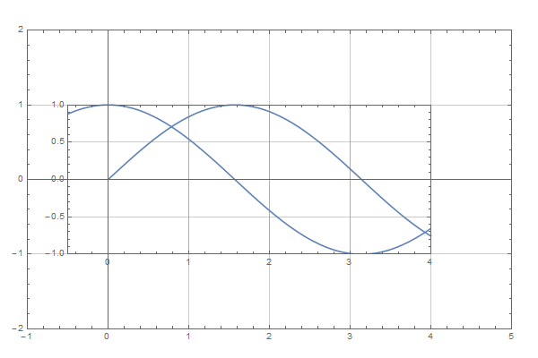
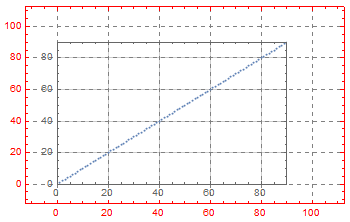
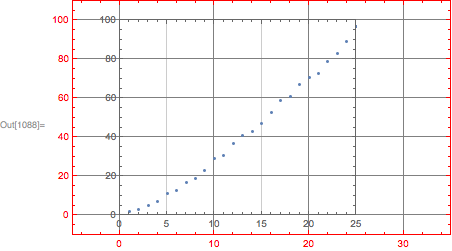
SetOptions[Plot, {GridLines -> Automatic, Frame -> True}] gr1 = Plot[Sin[x], {x, 0, 4}, PlotRange -> {{-1, 5}, {-2, 2}}, PlotRangeClipping -> False, ImageSize -> {600, 400}, ImagePadding -> 30] gr2 = Plot[Cos[x], {x, -.5, 4}, ImageSize -> {400, 300}, ImagePadding -> 30, PlotRange -> {{-.5, 4}, {-1, 1}}]
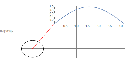
And producing the image:
Show[gr1, Epilog -> Inset[Show[gr2, ImageSize -> plotRangeRatio[gr2, gr1] printerPointsPlotRange[gr1] + (realImageDimensions[gr2] - printerPointsPlotRange[gr2]), AspectRatio -> (Last[#]/First[#] &)@ (plotRangeRatio[gr2, gr1] printerPointsPlotRange[gr1])], {0, 0}, {0, 0}, Automatic]]
The main assumption here is that the image padding is fixed and does not change upon resizing the image. It should then be always equal to
(realImageDimensions[gr2] - printerPointsPlotRange[gr2])
where I do not even care, how wide the padding is on which side, all I care is how much bigger the image is, compared to the size of the plot range. So for plots with ImagePadding of 30, or {{5,55},{20,40}} or {{35,25},{50,10}} the above code will in all cases return {60,60}.
Upon aligning the coordinates the aspect ratio of the graphic being enclosed may change depending on the coordinate scales of the enclosing graphic. It is thus calculated beforehand and set to the appropriate value.
AspectRationis notAutomaticand both the inset and enclosing graphics have non-zeroImagePadding. $\endgroup$ImagePaddingof the inset (valid and expected behavior, but somewhat complicates things). Does your question, nonetheless imply, that we know the padding of the inset anyway? Is it necessarily given as a fixed amount of printer points, or could it be inScaledorImageScaledcoordinates? Could it beAutomaticas well? $\endgroup$ImagePaddingaccepts only explicit values in printer's points orAll. Life would be much easier if this option would accept scaled specification. I assume thatImagePaddingfor the inset is specified in printer's points and is known. $\endgroup$