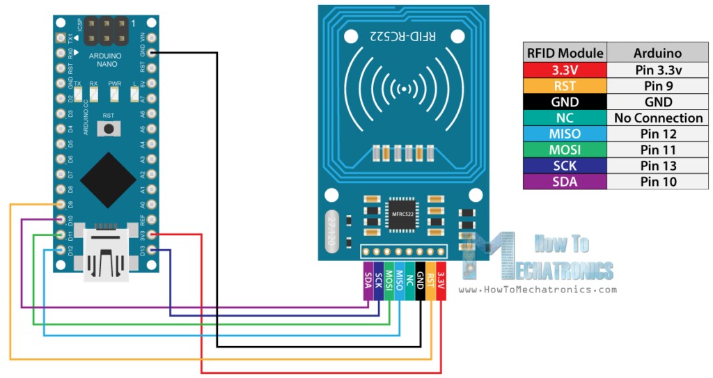
Hardware
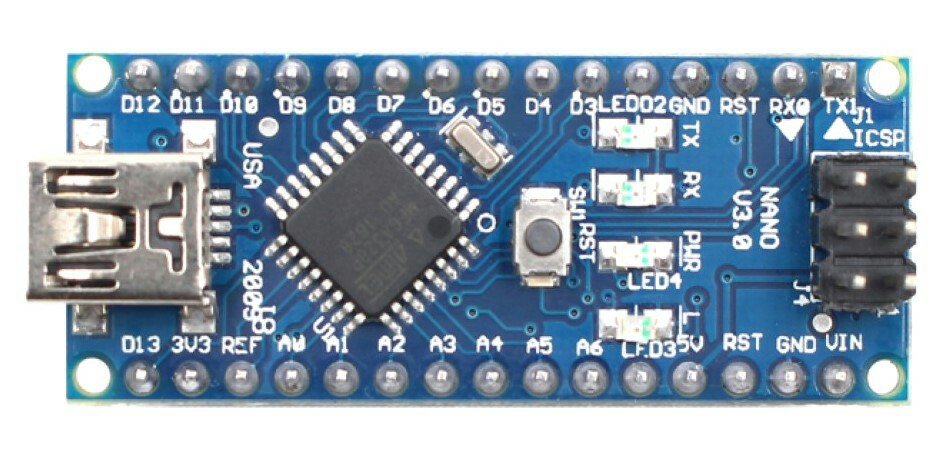
Dev Board: Arduino Nano V3.0
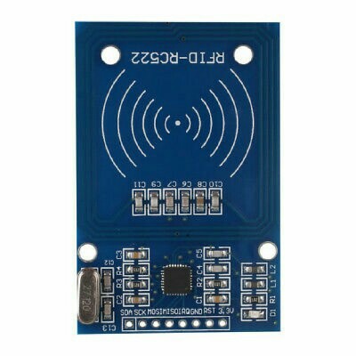
Module: RFID-RC522 13.56 MHz
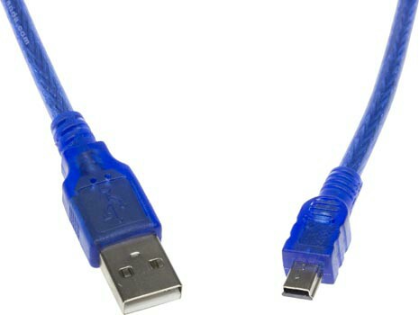
Cable: USB A - USB Mini B
Configuration
Physical
Code
/* * -------------------------------------------------------------------------------------------------------------------- * Example sketch/program showing how to read data from a PICC to serial. * -------------------------------------------------------------------------------------------------------------------- * This is a MFRC522 library example; for further details and other examples see: https://github.com/miguelbalboa/rfid * * Example sketch/program showing how to read data from a PICC (that is: a RFID Tag or Card) using a MFRC522 based RFID * Reader on the Arduino SPI interface. * * When the Arduino and the MFRC522 module are connected (see the pin layout below), load this sketch into Arduino IDE * then verify/compile and upload it. To see the output: use Tools, Serial Monitor of the IDE (hit Ctrl+Shft+M). When * you present a PICC (that is: a RFID Tag or Card) at reading distance of the MFRC522 Reader/PCD, the serial output * will show the ID/UID, type and any data blocks it can read. Note: you may see "Timeout in communication" messages * when removing the PICC from reading distance too early. * * If your reader supports it, this sketch/program will read all the PICCs presented (that is: multiple tag reading). * So if you stack two or more PICCs on top of each other and present them to the reader, it will first output all * details of the first and then the next PICC. Note that this may take some time as all data blocks are dumped, so * keep the PICCs at reading distance until complete. * * @license Released into the public domain. * * Typical pin layout used: * ----------------------------------------------------------------------------------------- * MFRC522 Arduino Arduino Arduino Arduino Arduino * Reader/PCD Uno/101 Mega Nano v3 Leonardo/Micro Pro Micro * Signal Pin Pin Pin Pin Pin Pin * ----------------------------------------------------------------------------------------- * RST/Reset RST 9 5 D9 RESET/ICSP-5 RST * SPI SS SDA(SS) 10 53 D10 10 10 * SPI MOSI MOSI 11 / ICSP-4 51 D11 ICSP-4 16 * SPI MISO MISO 12 / ICSP-1 50 D12 ICSP-1 14 * SPI SCK SCK 13 / ICSP-3 52 D13 ICSP-3 15 */ #include <SPI.h> #include <MFRC522.h> #define RST_PIN 9 // Configurable, see typical pin layout above #define SS_PIN 10 // Configurable, see typical pin layout above MFRC522 mfrc522(SS_PIN, RST_PIN); // Create MFRC522 instance void setup() { Serial.begin(9600); // Initialize serial communications with the PC while (!Serial); // Do nothing if no serial port is opened (added for Arduinos based on ATMEGA32U4) SPI.begin(); // Init SPI bus mfrc522.PCD_Init(); // Init MFRC522 mfrc522.PCD_DumpVersionToSerial(); // Show details of PCD - MFRC522 Card Reader details Serial.println(F("Scan PICC to see UID, SAK, type, and data blocks...")); } void loop() { // Look for new cards if ( ! mfrc522.PICC_IsNewCardPresent()) { return; } // Select one of the cards if ( ! mfrc522.PICC_ReadCardSerial()) { return; } // Dump debug info about the card; PICC_HaltA() is automatically called mfrc522.PICC_DumpToSerial(&(mfrc522.uid)); } See: https://github.com/miguelbalboa/rfid/tree/master/examples
Goal
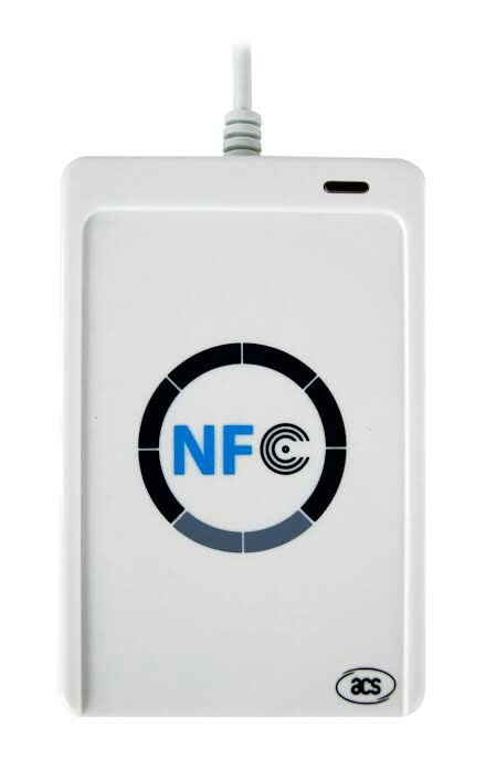
Generic USB-Compatible Mifare NFC Read/Writer
So, you can get these devices that just plug directly into your regular computer via USB, and basically function as an ordinary HID or peripheral device. I have various different ones from when I was investigating the security implications associated with CRYPTO-1 & MiFare Classic access control cards. They all basically work the same, and produce/dump the same standard output.
The thing is, I have little experience with Arduino, and hardware development in general. The Arduino USB Port is obviously used for serial communication with the IDE for programming the MEGA328P, and I can use the IDE's serial interface, plotter, etc. But it doesn't seem to want to play with any of the other applications (MiFare Classic Universal tooKit, etc.) that "just work" with the (unaffiliated) commercial/store-bought devices.