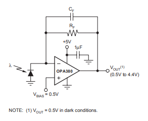
I'm in need of a different perspective here on how to approach the circuit I'm designing. Currently I have a PD that I want to reverse bias with 2V and measure the current from the PD. This is easy enough to do using a TIA IC like OPA380. I can even easily apply voltage to the INPUT+ to reverse bias the PD.
Unfortunately, this would only work for measuring the current in this condition. I don't think I can forward bias the PD and measure the current using this. One thought I had is to use 2 analog MUX ICs to just swap the PD polarity around. I think that will work since the current direction is still the same and I don't have to worry about voltage being negative.
Why am I measuring PD in a forward voltage mode? Well, I'm actually doing an IV characterization of the PD and trying to plot a current vs. voltage curve going from -1 Bias to +1 Bias on the PD. The design I have now would require having to measure from 0 to +1 twice to get my data (switching the polarity at 0V).
Are there other more elegant ways to measure the PD reverse and forward biased using the same TIA?