4
\$\begingroup\$

I know there are lots of similar questions and read them, but I need a simpler and clearer answer.

I understand why and how to use a pull up/down resistor when using a button (GPIO input). But while configuring a GPIO pin which will be connected to an LED, what is the use of these settings?

I tried no pull-up and pull-down and pull-up for example, but I could not see a difference in the implementation.

I am using STM32F407-DISC.

\$\endgroup\$
1

1 Answer 1

6
\$\begingroup\$

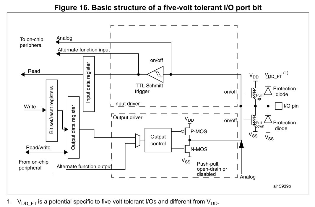
The pull up/down is only effective in Input or Open Drain configuration.
When set as output there is always an output MOSFET active, the pull up/down is then wasting energy.

The exception is open drain mode, this disables the P-MOS, then pull-up can be useful again.

Figure 25. Basic structure of a five-volt tolerant I/O port bit

\$\endgroup\$
2
  • \$\begingroup\$ But the raising edge will be quite slow with the internal (on chip) pull-up resistor(?). \$\endgroup\$ Commented Jul 29, 2019 at 19:38
  • \$\begingroup\$ @PeterMortensen Yes. It's ~40 kOhm. But if it's all you've got then it's at least something to keep the pin in a defined state. \$\endgroup\$ Commented Jul 29, 2019 at 20:17

Start asking to get answers

Find the answer to your question by asking.

Ask question

Explore related questions

See similar questions with these tags.