1
\$\begingroup\$

Can Someone clear this confusion... I have some Arduino pinout diagram, with the same logo "bq.com"...

I just find out, there are two types of pinout in those images... "MISO" & "MOSI" are altered.

Now I'm confused, and which one I used previously... Which one is correct? And why there are different pinout images by bq.com?

enter image description here

Full image:

https://i.sstatic.net/XE5Aw.png

https://i.sstatic.net/t51g9.jpg

https://i.sstatic.net/l2X02.png

https://i.sstatic.net/h4uNJ.png

\$\endgroup\$

2 Answers 2

2
\$\begingroup\$

If your Arduino is the official one, it should match the official documentation for the Arduino nano and Arduino mini pro (Check its version).

However, if it was produced by a third party, in order to avoid any problem you can just probe the pins and make sure that they are correctly wired to the MCU according to the following:

Arduino Nano AND Pro mini (normally) use a ATMEGA328 controller with MOSI, MISO and SCK connected respectively to the pins 15 (PB3), 16 (PB4) and 17(PB5).

\$\endgroup\$
1
  • \$\begingroup\$ Oh, thanks, I can just check by probe with ICSP pins...!!! \$\endgroup\$ Commented May 8, 2020 at 6:39
0
\$\begingroup\$

The Arduino Nano 3.2 schematic (here) shows:

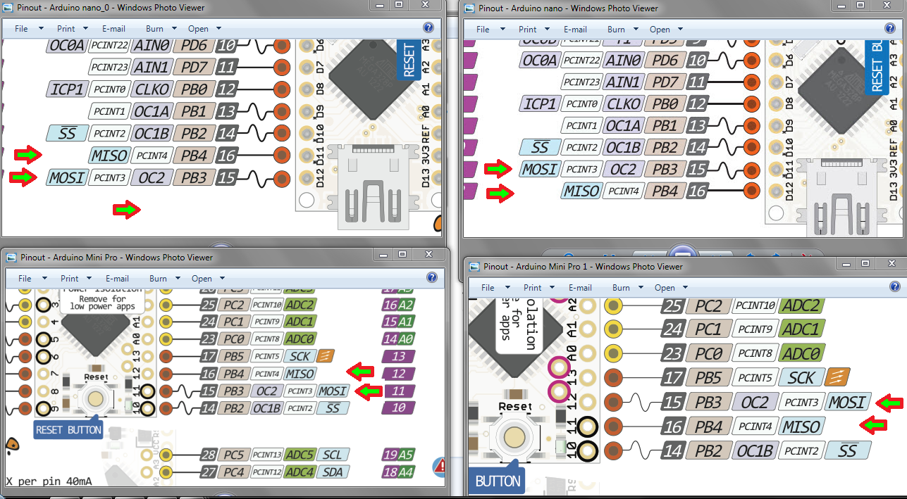
  • J2-15, D13: PB5 (which is SCK)
  • J1-15, D12: PB4 (which is MISO)
  • J1-14, D11: PB3 (which is MOSI)

The Arduino Pro Mini schematic (here) shows:

  • JP6-9, D13: PB5 (which is SCK)
  • JP6-10, D12: PB4 (which is MISO)
  • JP6-11, D11: PB3 (which is MOSI)

I would consider the schematics to be authoritative since the boards were laid out with them. The graphic, on the other hand, is someone's pretty doc that may or may not reflect the actual design.

Knowing how the ATMega328 pinout flows, the ones that go PB5/3/4 seem... odd. Like a mistake. And that sequence doesn't follow the 'D' numbering as marked on the board.

I suggest you get the schematic from bq.com, check it against the rev of board that you have. They seem to have swapped those pins somewhere. tsk, tsk... naughty of them.

\$\endgroup\$
2
  • \$\begingroup\$ Yes, I refer digital pin to connection, I checked schematic, so, D11 is MOSI.. In the images, Digital pins and description doesn't match... I think some of the images are wrong or custom made for some reason... \$\endgroup\$ Commented May 9, 2020 at 21:35
  • \$\begingroup\$ And I just find this post...lab.dejaworks.com/arduino-nano-pinouts \$\endgroup\$ Commented May 9, 2020 at 21:57

Start asking to get answers

Find the answer to your question by asking.

Ask question

Explore related questions

See similar questions with these tags.