I am trying to control 13 different servos with my Spartan3 FPGA. For that, I need 13 independent PWM signals generated by my FPGA. The PWM module that I am using works perfectly fine when only one output pin is controlled (instantiated as follows).
SERVO_1 : entity work.Servo(Behavioral) port map ( clk => clk, rst => rst, position => s_pos_1, -- integer from 0 to 255 (256 steps from 0° to 180°) pwm => pwm_1 -- output pin of FPGA ); But as soon as I add more servo entities, the output of the PWM pins behave unexpectedly. Some are constantly high, low, or are constant in their pulse width (frozen). Overall, the behaviour is (for me) kind of random (talking about actual hardware behavior). I instantiate the entities as follows:
SERVO_1 : entity work.Servo(Behavioral) port map ( clk => clk, rst => rst, position => s_pos_1, pwm => pwm_1 ); SERVO_2 : entity work.Servo(Behavioral) port map ( clk => clk, rst => rst, position => s_pos_2, pwm => pwm_2 ); SERVO_3 : entity work.Servo(Behavioral) port map ( clk => clk, rst => rst, position => s_pos_3, pwm => pwm_3 ); -- ... and so on What I checked so far
- The simulation works as expected, every pwm output behaves correctly.
- I can safely say that the problem has nothing to do with the servos/current/power supply/drivers.
- I am checking the outputs on a scope all the time.
- Checked that there are no signals without default value
- Changed multiplication in VHDL to accessing a ROM with the needed values (which were multiplicated before, I thought that maybe the multiplication part caused the problems)
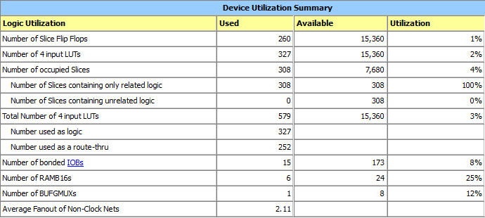
- Checked the logic utilization of my FPGA, which is rather low
- Checked the timing report of ISE Webpack, no errors
Besides that I get no errors during synthesis.
There are two infos regarding timing:
- Timing:3390 - This architecture does not support a default System Jitter value, please add SYSTEM_JITTER constraint to the UCF to modify the Clock Uncertainty calculation.
- Timing:3389 - This architecture does not support 'Discrete Jitter' and 'Phase Error' calculations, these terms will be zero in the Clock Uncertainty calculation. Please make appropriate modification to SYSTEM_JITTER to account for the unsupported Discrete Jitter and Phase Error
Source code of Servo.vhd:
library ieee; use ieee.std_logic_1164.all; use ieee.numeric_std.all; use ieee.math_real.round; entity Servo is port ( clk : in std_logic; rst : in std_logic; position : in integer range 0 to 255; pwm : out std_logic ); end Servo; architecture Behavioral of Servo is constant clk_hz : real := 50.0e6; -- 50 MHz Spartan3 constant pulse_hz : real := 50.0; -- 50 Hz PWM-Signal constant min_pulse_us : real := 500.0; -- 0° pulse width constant max_pulse_us : real := 2500.0; -- 180° pulse width constant step_bits : positive := 8; -- 0 to 255 constant step_count : positive := 2**step_bits; -- Number of clock cycles in Microseconds function cycles_per_us (us_count : real) return integer is begin return integer(round(clk_hz / 1.0e6 * us_count)); end function; constant min_count : integer := cycles_per_us(min_pulse_us); -- 0° in clock cycles constant max_count : integer := cycles_per_us(max_pulse_us); -- 180° in clock cycles constant min_max_range_us : real := max_pulse_us - min_pulse_us; constant step_us : real := min_max_range_us / real(step_count - 1); constant cycles_per_step : positive := cycles_per_us(step_us); -- clock cycles per step (1/256) constant counter_max : integer := integer(round(clk_hz / pulse_hz)) - 1; -- clock cycles for 20 ms (50 Hz) signal counter : integer range 0 to counter_max; signal duty_cycle : integer range 0 to max_count; begin -- position <= to_integer(rom_data); COUNTER_PROC : process(clk) -- basic counter begin if rising_edge(clk) then if rst = '1' then counter <= 0; else if counter < counter_max then counter <= counter + 1; else counter <= 0; end if; end if; end if; end process; PWM_PROC : process(clk) -- Setting the pwm pin according to duty_cycle begin if rising_edge(clk) then if rst = '1' then pwm <= '0'; else pwm <= '0'; if counter < duty_cycle then pwm <= '1'; end if; end if; end if; end process; DUTY_CYCLE_PROC : process(clk) -- Setting the duty_cycle begin if rising_edge(clk) then if rst = '1' then duty_cycle <= min_count; else duty_cycle <= position * cycles_per_step + min_count; end if; end if; end process; end Behavioral; 'clk' is connected to the 50 MHz oscillator pin. 'rst' is a signal and comes from a reset module that synchronizes everything with 3 FFs.