0
\$\begingroup\$

LM317HV data sheet provides following reference circuit for use as a "simple, fixed-current regulator" in section 9.2.9.

1-A Current Regulator

It also specifies typical load regulation of 0.1%. I don't think the formula from Wikipedia applies to the above circuit.

enter image description here

So how would the change in load or R1 resistance due to temperature fluctuation or other factors affect the current output?

\$\endgroup\$

3 Answers 3

1
\$\begingroup\$

You have two separate questions. First, the formula (with currents at miminum and maximum load resistances substituted for voltages) is applicable. This is only the effect of changing current with load resistance. Everything else is understood to be held constant, including the input voltage, the junction temperature of the LM317HV and the resistance of R1.

Of course they have made some (unstated) assumptions about the minimum voltage across the LM317HV and therefore the minimum and maximum resistances and input voltage. If we assume a minimum load of 0Ω and a maximum of 10Ω, then we would need to apply a minimum of 10.4 + 1.25 + 3 or about 15V to have a minimum of 3V across the regulator chip. Vin-Vout would change from 3V to almost 14V as the load resistance changes, or about 11V. The datasheet suggests the resulting change in output voltage will be about 0.01%/V or about 0.11%.

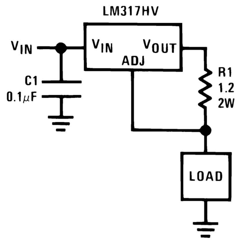
There is an additional term in the current regulator circuit- the adjustment current is added to the nominal output current of Vref/R1. The ADJ current, however, is only 50uA typically so it's a small percentage of the nominal 1.04A output current of the given circuit. So if one scales down the output current (say to 20mA) by increasing R1 to about 62.5Ω, the ADJ current will represent more than 50x as much error in the output current. There is not much information in the datasheet on what happens with the ADJ current as the voltage Vin-Vout changes.

You ask about the effects of R1, temperature etc. Those effects are all additive. They may add positively or negatively. For example, the datasheet does give typical change of ADJ current with temperature. The reference voltage will change with temperature (typical and maximum figures given in the datsheet). And, of course, if R1 changes by 1%, the output current will change by almost exactly 1%. Since the given circuit is operating at a relatively high power dissipation (minimum ~3W dissipation in the regulator and about 1W in the resistor), the junction temperature and the resistor temperature will change significantly as the parts heat up. There is also the effect of input voltage (line regulation), which in turn, has a great effect on the junction temperature of the LM317HV (and therefore the reference voltage and ADJ current). A subtle effect is the change of junction temperature with load resistance. There will be a long (thermal time constant) tail to the effect of change in load resistance as the junction temperature changes. The 0.1% may be true for 100usec after the load resistance changes from max to min, but after a few minutes it might be much, much more.

In general, as a comment, this is not really a suitable circuit for a "0.1%" stable current source, nor is it great if you need good compliance (low minimum voltage drop across the current regulator) or decent performance at much lower currents than 1A. It is simple, relatively cheap and makes a good datasheet example, but there are good reasons it's very seldom, if ever, used in real life in the form shown.

\$\endgroup\$
3
  • \$\begingroup\$ So, if you were to calibrate it by adjusting R1 to produce 10mA across 1k load, then change the load to 2k, you wouldn't get exactly 10mA, you would get less, right? I can't quite calculate how much less exactly. I'm assuming constant temperature for this. \$\endgroup\$ Commented Nov 10, 2023 at 12:36
  • \$\begingroup\$ Yes, you would get less. At such a low current the 50uA (typical) ADJ current is a much bigger factor than at ~1A (100x more effect). If you ignore that (and you shouldn't if you want a correct answer, but there's not enough information in the datasheet to include it) you can calculate the change from the line regulation figures in the datasheet, as I did above. Really if you want a quick 'typical' figure, just build it and measure it. I would not depend on simulation to get the ADJ current variation correct. If you need guarantees, a different circuit would be a good idea. \$\endgroup\$ Commented Nov 10, 2023 at 12:41
  • \$\begingroup\$ Fair enough. What circuits do you recommend I look into? I know it depends on my requirements, but I'm looking to learn a bunch of stuff about different constant current sources as well. Ideally I'd have ~300V 10-500mA precision adjustable constant current source/sink. \$\endgroup\$ Commented Nov 10, 2023 at 14:08
1
\$\begingroup\$

The wikipedia formula does apply, with the obvious change as you have a current output

Load regulation % = \$100 \frac{I_{min-load}-I_{max-load}}{I_{nom-load}}\$

As R1 controls the output current, changes in R1 would linearly affect the output current.

You would need to look at the 317 data sheet to see how temperature fluctuations affect the adjust pin current, which is added to the output current. Also check how input voltage, output voltage, and temperature, all affect the adjust pin voltage, which changes the voltage across R1, and hence the output current.

\$\endgroup\$
0
\$\begingroup\$

It also specifies typical load regulation of 0.1%. I don't think the formula from Wikipedia applies to the above circuit.

That formula applies to constant current sources as well because the output voltage (or load resistance) can be used to rate the load regulation of a CC regulator i.e. if the output voltage reaches its max the constant output current shouldn't change:

$$ LR_{\text{%}} =100\ \frac{I_{omax}-I_{omin}}{I_{onom}} $$

For example, if I had a 1-Amp constant current source for an output voltage range of, say, 1~100V, I want its output current to be 1.00A for a 1-Ohm load or a 100-Ohm load.

However, the load regulation spec of 0.1% may not apply to the given CC configuration because 1) the rating heavily depends on the external component, R1, since not all 2W 1R2 resistors change by the same amount with temperature, and also the test conditions mention only the junction temperature of 25°C, and 2) we normally expect to see specific test circuits for some datasheet specs yet there's none given. I presume the spec is given for the CV config, but can't say if it applies to CC config as well.

So how would the change in load or R1 resistance due to temperature fluctuation or other factors affect the current output?

That's totally a different story. The load regulation formula applies to CV and CC regulators in general. So the effect of resistance change should be included in the LR percentage. As I mentioned above, 0.1% of load regulation may not apply to the given CC configuration.

\$\endgroup\$

Start asking to get answers

Find the answer to your question by asking.

Ask question

Explore related questions

See similar questions with these tags.