2
\$\begingroup\$

I'm trying to adapt a current limiter design that I found, and I'm having trouble understanding the "current sense" part of it.

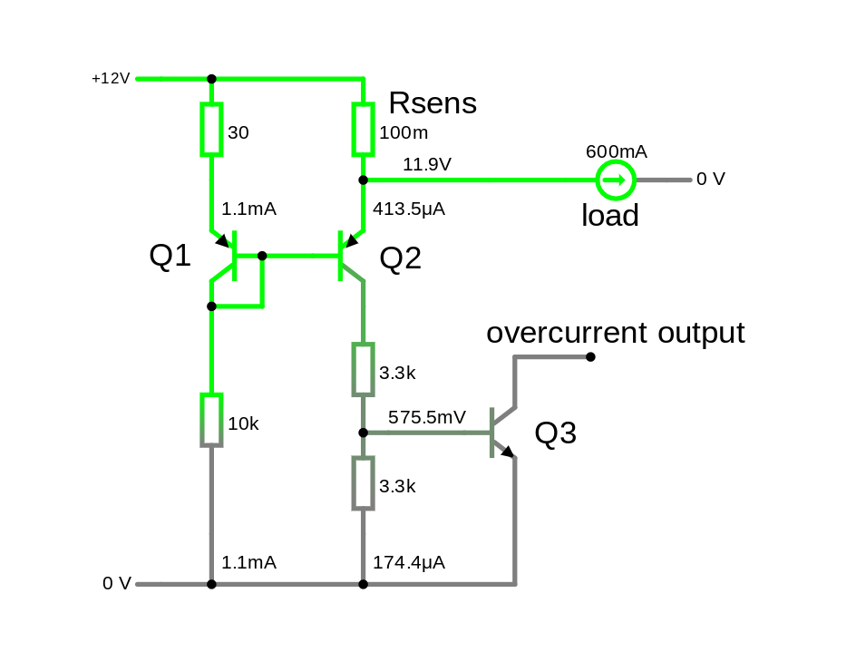
The current sensing is implemented using a shunt resistor, which is then measured using a current mirror using the circuit below.

schematic

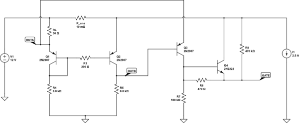
simulate this circuit – Schematic created using CircuitLab

The designated output nodes (OUTA, OUTB) are then fed into a simple amplifier, which in turn drives the a high-side PMOS FET gate (GATE).

In theory this circuit should allow current to pass up-to a limit that is set by RL, and afterwards put the high-side FET into linear region to limit the current.

I'm trying to understand how the current sense part of this circuit works, and how one would analyze and select the resistor values for a given current limit, input voltage, etc.

Most of the designs for current sensing using a current mirror I've seen employ a emitter resistor on Q1 (e.g. 1), which is used to set the quiescent current based on the maximum sense voltage deviation, but this design does not have this so I'm having trouble to start with the analysis.

Any pointers would be highly appreciated.

EDIT: updated schematics to fix gate short and provide easy simulation

\$\endgroup\$
7
  • 2
    \$\begingroup\$ @Malte The question editor has a schematic editor button that will insert a CircuitLab schematic and let you edit it. Please use it instead of pasting images of circuits from the CircuitLab.com site. Then your circuits can be simulated easily, and anyone answering your question could copy them to their answer and set up whatever simulations and/or changes needed. \$\endgroup\$ Commented Feb 12, 2024 at 17:17
  • 2
    \$\begingroup\$ Q2 in the second schematic will just burn out directly connected across 12 V. Why is GATE connected to GND? \$\endgroup\$ Commented Feb 12, 2024 at 19:17
  • 2
    \$\begingroup\$ You may find this of interest: electronics.stackexchange.com/a/700329/311631 \$\endgroup\$ Commented Feb 12, 2024 at 21:35
  • 2
    \$\begingroup\$ Also: electronics.stackexchange.com/questions/277399/… \$\endgroup\$ Commented Feb 12, 2024 at 21:36
  • 2
    \$\begingroup\$ One more: electronics.stackexchange.com/questions/410074/… \$\endgroup\$ Commented Feb 12, 2024 at 21:37

1 Answer 1

1
\$\begingroup\$

Below is what I think is the general idea of this type of circuit (clickable link). aaa

When the V drop across the 30ohm and R_sens are equal, then Q1 and Q2 are in balance, and about 1mA comes out of Q2's collector. The the open-collector output at Q3 is normally on in this case. It's also normally on when there isn't any V drop in Rsens.

As load increases beyond that balance point, larger V drop across R_sens gradually reduces Q2's Vbe, Q2 current falls, and eventually Q3's open-collector output turns off.

The 30 ohm isn't really necessary but lets you add an offset to the balance point, i.e. change the threshold without having to play with the typical load in Q1 and Q2.

The top 3.3k resistor is possibly redundant, but in case a large reverse load current flows, it should limit current thru Q2 into Q3's base.

Finally, depending on how it's set up, this concept might not be the best when applied as an overcurrent circuit (vs when applied within a feedback loop), because Q2 could be saturated in the normal-load condition, so it mightn't be fast enough turning off the output.

\$\endgroup\$
3
  • \$\begingroup\$ Thank you very much Pete, that already helps quite a bit. A few more questions if I may: - How would I set the balance point current in this circuit? Do I change the 10k resistor below Q1? And how can I calculate the resistance value for a given current. - How does the value of my sense resistor play into this, does it need to be selected to a certain max voltage drop for my maximum load current? If so, how does that correlate to the other resistance values in the circuit In general I'm trying to get a bit more of a mathematical understanding of how to size this circuit. \$\endgroup\$ Commented Feb 13, 2024 at 8:32
  • 1
    \$\begingroup\$ @Malte - you can tune using the 30ohm. The 10k can in principle also be used, but that one should really be just to set the bias current (and thus power consumption. So it's probably easier to leave all those alone, and use the 30ohm. The turn-off condition is when the Vbe of Q3 falls below some nominal value, like maybe 450mV. (depends on what the output is going into of course, and Q3 temperature etc). Take a look at the links Tim Williams added in the comments, I think some of them have formulas. \$\endgroup\$ Commented Feb 13, 2024 at 15:15
  • 1
    \$\begingroup\$ also note, your circuit has the "output" of the balance, which comes is the V at the top of R5, going into a PNP ... so it's all different after that. \$\endgroup\$ Commented Feb 13, 2024 at 15:22

Start asking to get answers

Find the answer to your question by asking.

Ask question

Explore related questions

See similar questions with these tags.