


A 7-segment display is commonly used in electronic display devices for decimal numbers from 0 to 9 and in some cases, basic characters. The use of light-emitting diodes (LEDs) in seven-segment displays made it more popular, whereas of late liquid crystal displays (LCD) have also come into use.
Electronic devices like microwave ovens, calculators, washing machines, radios, digital clocks, etc. to display numeric information are the most common applications. Let’s take a look at the seven display pinout to have a better understanding.

Table of Contents
7-Segment Display Pinout
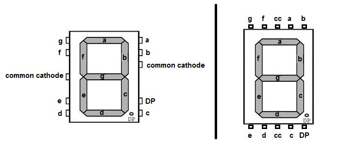
A seven-segment display is made of seven different illuminating segments. These are arranged in a way to form numbers and characters by displaying different combinations of segments.
The binary information is displayed using these seven segments. LED is a P-N junction diode that emits energy in the form of light, different from a standard P-N junction diode which emits in the form of heat.
Whereas LCD uses liquid crystal properties for displaying and does not emit light directly. These LEDs or LCDs are used to display the required numeral or alphabet.
Seven Segment Display Types
There are basically 2 types of seven-segment LED displays:
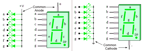
1. Common Anode 7 Segment Display:
All the Negative terminals (Anode) of all the 8 LEDs are connected together. All the positive terminals are left alone.
2. Common Cathode 7 Segment Display:
All the positive terminals (Cathode) of all the 8 LEDs are connected together. All the negative thermals are left alone.
Seven-Segment Display Working
Seven-segment devices are generally made up of LEDs. These LEDs will glow when they are forward-biased. The intensity of the LEDs depends on the forward current.
So, a sufficient forward current has to be provided to these LEDs to glow with full intensity. This is provided by the driver and is applied to the seven segments.
7-Segment Display Codes
The below table shows the 0-9 codes for the seven-segment LED display.
| Number | g f e d c b a | Hex code |
| 0 | 1000000 | C0 |
| 1 | 1111001 | F9 |
| 2 | 0100100 | A4 |
| 3 | 0110000 | B0 |
| 4 | 0011001 | 99 |
| 5 | 0010010 | 92 |
| 6 | 0000010 | 82 |
| 7 | 1111000 | F8 |
| 8 | 0000000 | 80 |
| 9 | 0010000 | 90 |
Table: Display numbers on a seven-segment display in common anode configuration
Things change for common cathode configuration.
| Number | g f e d c b a | Hex Code |
| 0 | 0111111 | 3F |
| 1 | 0000110 | 06 |
| 2 | 1011011 | 5B |
| 3 | 1001111 | 4F |
| 4 | 1100110 | 66 |
| 5 | 1101101 | 6D |
| 6 | 1111101 | 7D |
| 7 | 0000111 | 07 |
| 8 | 1111111 | 7F |
| 9 | 1001111 | 4F |
Table: Display numbers on a seven-segment display in common cathode configuration
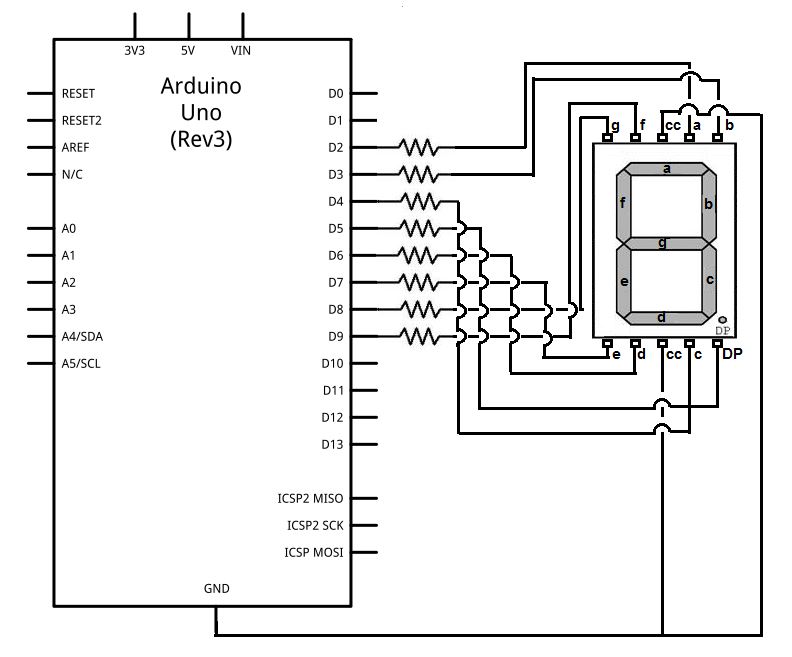
Below we are interfacing a 7-segment display to Arduino UNO for reference.
7-Segment Display-based Projects
For more technical information, you can refer to the 7-Segment Display Datasheet.
People Also Ask
Which segments are switched on to display the digit 6 on a seven-segment display?
Segments a, b, d, e, f, g are ON; segment c is OFF.
How does a 7-segment display unit work?
Each segment in a 7-segment display is individually controlled to turn on or off. By selectively activating specific segments, you can form the desired digit or character. For example, to display the digit ‘5’, you would activate the segments necessary to create its visual representation.
How many seven-segment displays are needed to show numbers from 0 to 15 (binary system)?
You need 4 displays (since 0–15 is 4-bit binary).
How many seven-segment displays are needed to show integers from –10 to +10?
You need 3 displays (minus sign + two digits).
How many seven-segment displays are needed to indicate integers from 0 to 10?
You need 2 displays (two-digit numbers needed for 10).
In a common-anode seven-segment display, segments a–g and the dot must be connected to what?
They must connect to logic LOW (ground) to turn ON.
How many pins does a typical common-cathode seven-segment display have?
Usually 10 pins (8 segment pins + 2 common cathodes).
In a common-cathode display, segments a–g and the dot must be connected to what?
They must be connected to logic HIGH to turn ON.
Which Arduino function is used to turn ON/OFF segments of a seven-segment display?
Use digitalWrite().
Which LEDs (segments) must be HIGH/LOW to display digit 2?
Segments a, b, d, e, g ON; segments c, f OFF.
A seven-segment display has how many segments?
7 segments (plus an optional decimal point).
How many function tables are needed for a seven-segment decoder?
Seven (one for each output segment a–g).
Which segments light up to display the number 5?
Segments a, c, d, f, g ON.
In a common-cathode type display, the negative terminals are connected to what?
Connected to common pins (ground).
A simple numeric display made of bar-shaped LEDs is called what?
A seven-segment display.
In a common-anode display, the common pin is connected to what logic level?
To HIGH (VCC).
How many seven-segment indicators are needed to display 0–15 using hexadecimal?
You need 2 (two-digit hex numbers: 00–0F to FF).
What is the purpose of a seven-segment display in Arduino projects?
To display numerical digits.
How many seven-segment displays are required to show values from –1 to +1?
2 displays (minus sign + digit).
What circuit converts binary input into seven-segment patterns?
A seven-segment decoder (BCD-to-7-segment decoder).
How many displays are needed to show values from 0 to 7 (binary)?
3 displays (since 0–7 requires three binary digits).
To design expressions for 7-segment outputs, how many-variable Karnaugh maps are used?
Four-variable K-maps (inputs A, B, C, D).
Which Arduino function is used to display numbers on a 7-segment display?
digitalWrite() (to control pins).
A seven-segment display used in digital clocks and meters is also known as what?
A numeric display.
This article was first published on 29 December 2016 and updated in November 2025.
In common anode, All the Positive terminals (Anode) of all the 8 LEDs are connected together. All the negative terminals are left alone.
Common Cathode: All the negative terminals (Cathode) of all the 8 LEDs are connected together. All the positive thermals are left alone.
For the cathode 9’s hexcode will be 6f instead of 4f.
Can someone in charge of this page fix this?
You say: “Types of 7 segments
There are basically 2 types of 7 segment LED display.
Common Anode: All the Negative terminals (cathode) of all the 8 LEDs are connected together. All the positive terminals are left alone.
Common Cathode: All the positive terminals (anode) of all the 8 LEDs are connected together. All the negative thermals are left alone.”
This is backwards.