advanced raiway security system based on zigbee communication for track fault
This document describes a proposed crack detection robot system for railway tracks. It would use sensors to detect cracks in the rails and send alert messages using Zigbee communication. The system aims to address safety issues caused by undetected rail cracks. It proposes using a microcontroller and sensors to detect cracks, and Zigbee to wirelessly transmit warnings to nearby stations. The document discusses related work on visual, vibration, and gauge inspection methods, and outlines the components and advantages of the proposed robotic crack detection system.
The slide lists the contents to be covered in the presentation, including abstract, literature survey, problem identification, and others.
The abstract discusses a crack detector robot utilizing ZIGBEE communication to identify faults in railway tracks to enhance safety.
A survey of existing technologies for automatic visual inspection of railroad tracks to improve safety and efficiency.
Details on methods using vibration sensors and computer vision for inspecting railway track conditions and gauge irregularities.
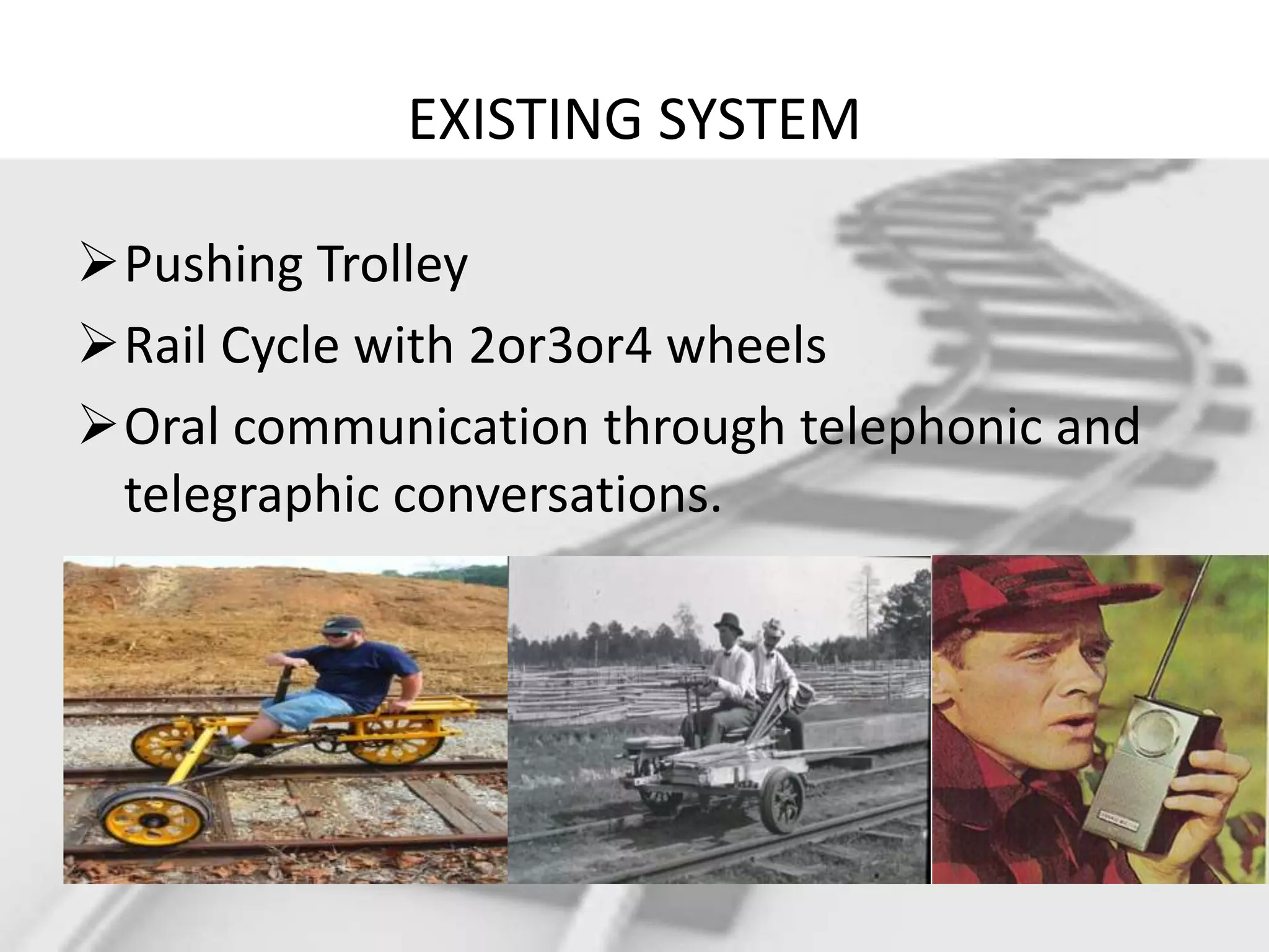
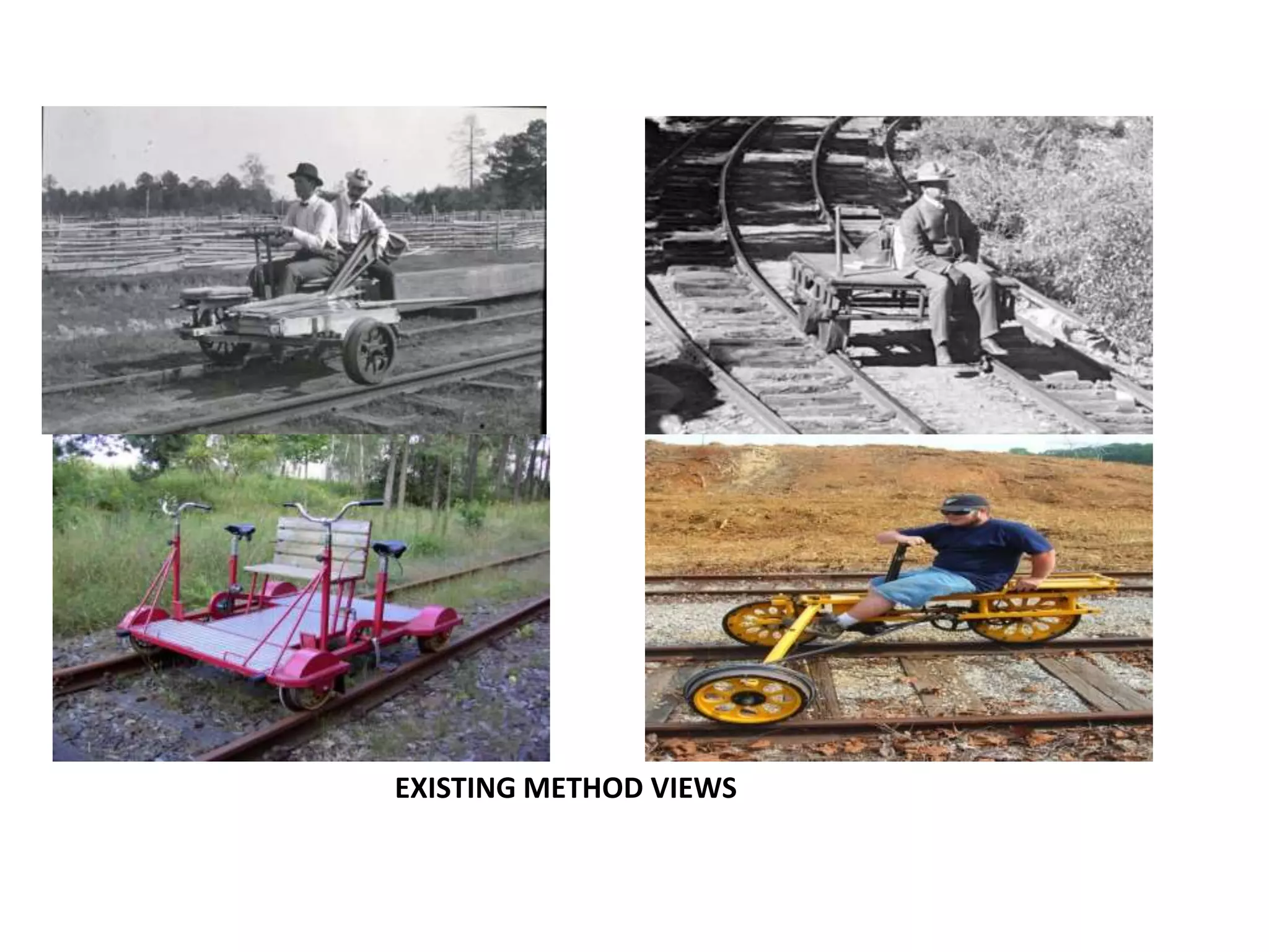
Description of traditional systems for rail inspection, like pushing trolleys and rail cycles.
Identification of issues with cracks in railway tracks and the proposed design for a robotic crack detection system.
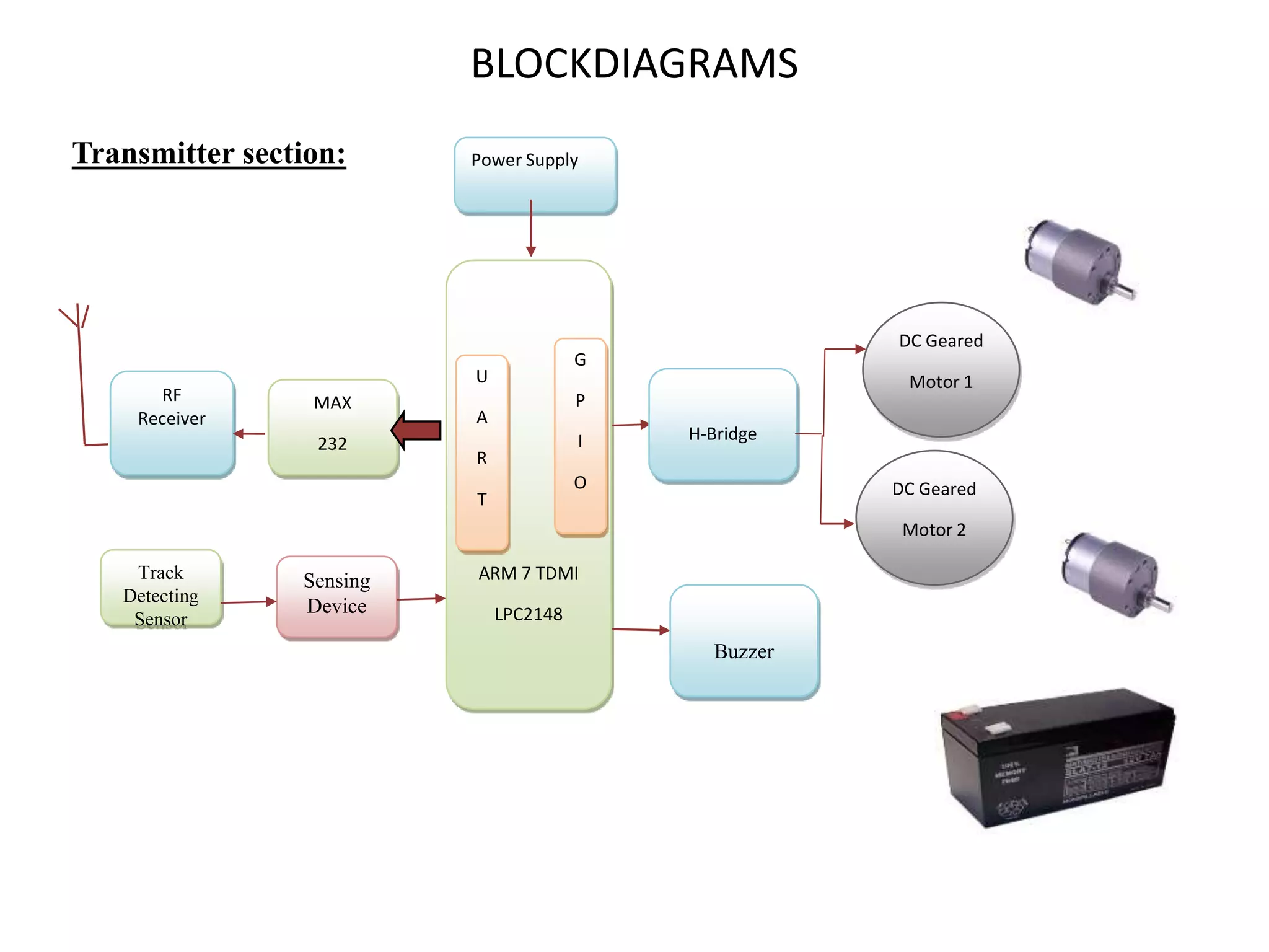
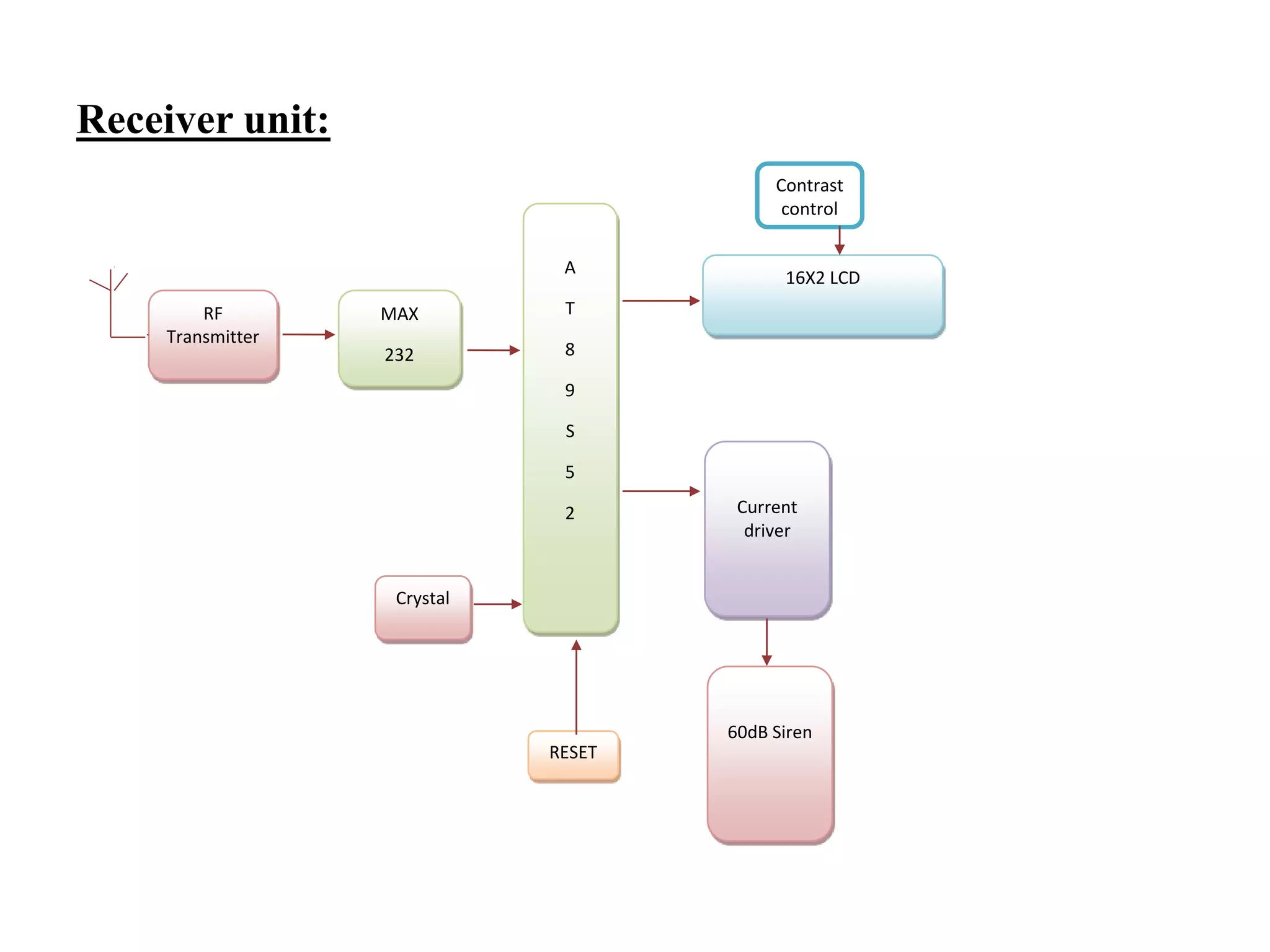
Block diagrams illustrating the design and components of the proposed crack detection robot, including various sensors.
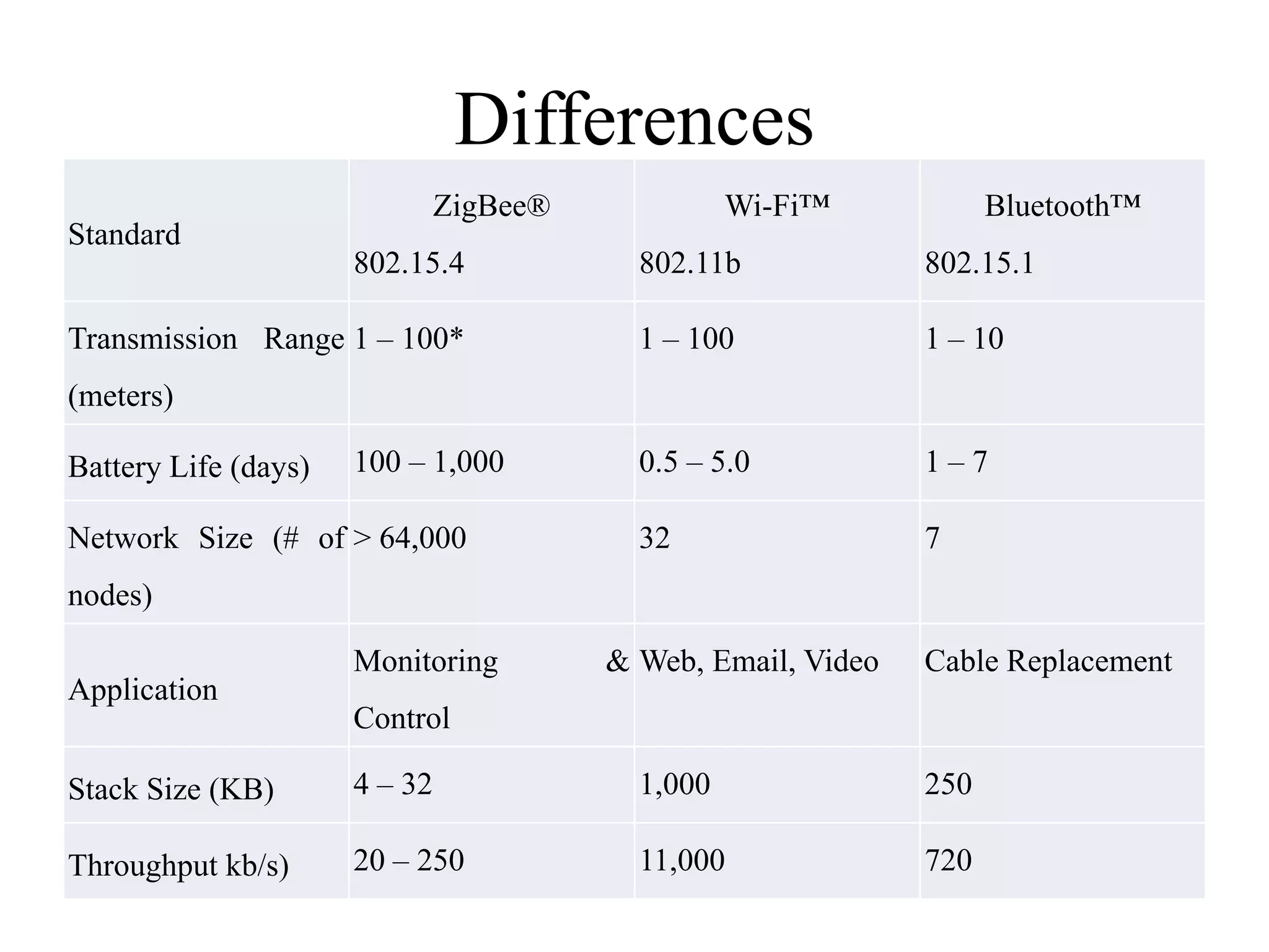
Explanation of the ZigBee protocol for wireless communication in low-power applications, comparing it with other standards.
Descriptions of components like MAX232, LPC 2148, AT89S52, UART, and GPIO related to the robotic system.Discussion on traditional inspection methods and the advantages of using a crack detector robot for improved fault detection.
Outlines the advantages of robotic systems in rail inspections, highlighting efficiency, manpower reduction, and high accuracy.
Proposal for geographical sensors on trains to track their locations and enhance track fault detection.
Emphasizes the need for continuous monitoring of railway tracks to prevent accidents and ensure safety.
A list of scholarly references that support the research and findings presented in the presentation.
Concluding slide thanking the audience for their attention.
ABSTRACT • The Transportationof train always depends on railway tracks (rails) only. If there is a crack in these rails, it creates a major problem. Most of the accidents in the train are caused due to cracks in the railway tracks, which cannot be easily identified. In order to avoid this problem, we are using the crack detector robot,By the using of this method to identifying rail track fault sending message to near station using ZIGBEE communication.
5.
LITERATURE SURVEY VISUAL INSPECTIONMETHOD by Ashwini Belkhade, Snehal Kathale First organized a survey of existing technologies of automatic visual inspection of railroad track and track components. This gave understanding with respect to which assignments were best suited to vision based assessment for which technology was not already under development. This survey encompassed well-established inspection technologies and experimental technologies currently under development.
6.
• Safety inrailways is one of the major issues for public transportation organization and a fast and efficient inspection system is vital to ensure the safety of railways. Authors had tried to provide effective solution on the problem.
7.
• Automatic railroadtrack inspection with the help of vision based method. Vision based system there are some cameras for collecting the images or videos of rail track and process the frame image by using image processing. • In such manner it could enhance the efficiency of the traditional methods. • The System challenges the following addressed: detection,fragmentation,deformity evaluation of track components whose physically appearance vary across number of tracks and the identification and inspection of track areas such as track turnouts.
8.
VIBRATION BASED METHOD M.Singh, S.Singh1,J.Jaiswal In this method a sensors will sense the vibration with the help of vibration sensor and after that it will pass to the op-amplifier filter for removing external noise and microcontroller for programming. There is one communication protocol to establish the connection between the hardware and system .In system processing will be done and than it will broadcast to the server through wireless medium.
9.
RAIWAYGAUGE INSPECTION METHOD S.Zheng,X.An, X.Chai • Railway track gauge irregularity severely reduces the service life of rail and vehicle, and even result in vehicle falling off rail or wheel trapping, which causes driving accidents. In this project a dynamic inspection method of track gauge based on computer vision is presented. According to the method, the inspection system could be constructed by using four CCD (Charge-coupled Device) cameras and two red laser sector lights. • The inspection principle and corresponding calibration method of inspection system are analyzed. In order to get the gauge points, several image processing technologies, including image component extraction, differential, adaptive iteration threshold, dilation and thinning are adopted. • At last, the experiment results prove that this inspection method is capable of fast obtaining track gauge value with high accuracy and repeatability, and meeting the requirement of dynamic inspection for track gauge.
PROPOSED SYSTEM thedesign of crack finding robot for finding cracks in railway tracks,This system uses controller for interfacing the robotic vehicle and crack detection sensor. The sensing device senses the voltage variations from the crack sensor(IR) and then it gives the signal to the microcontroller from that connected to zibgee communication.
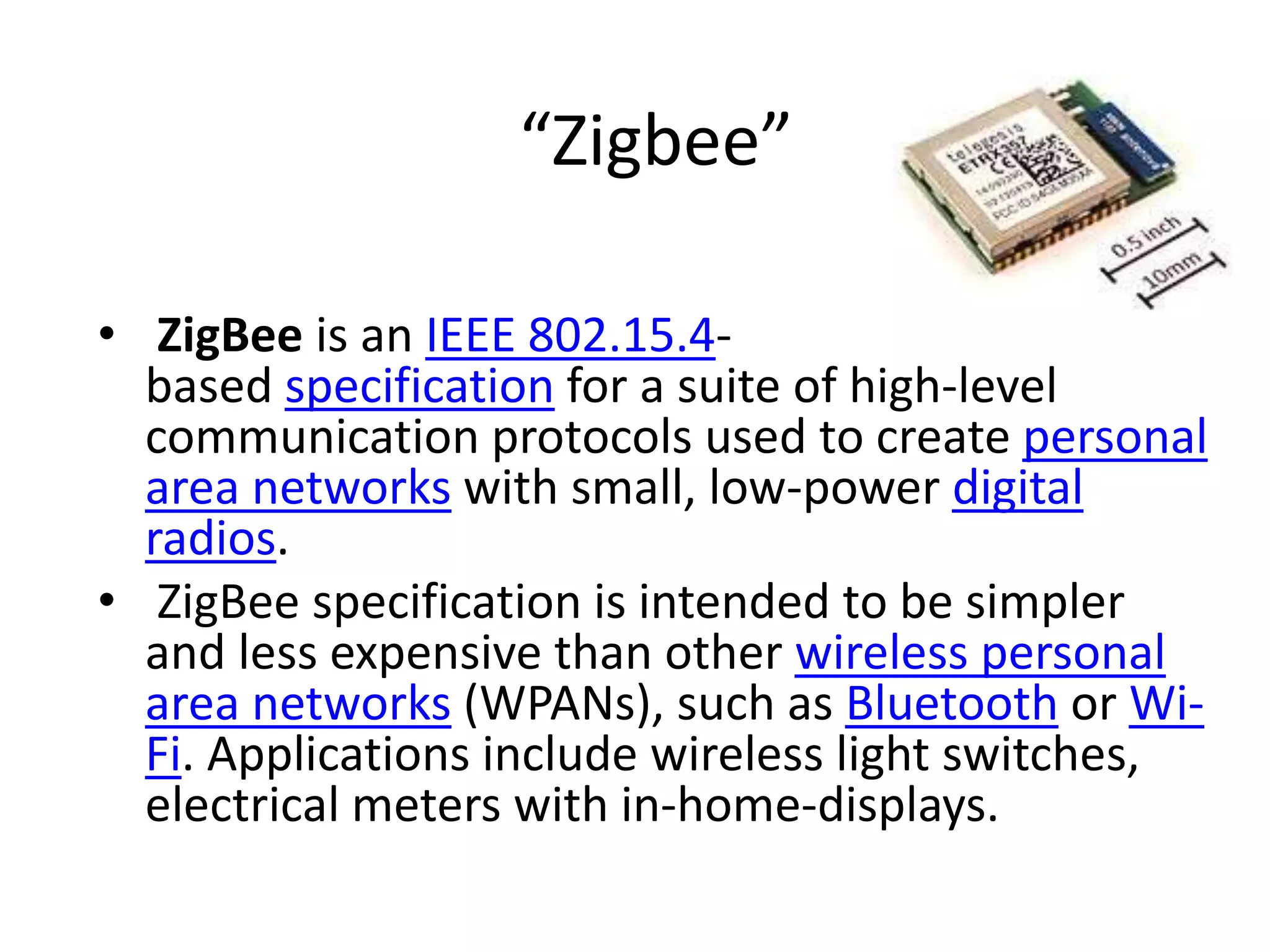
“Zigbee” • ZigBee isan IEEE 802.15.4- based specification for a suite of high-level communication protocols used to create personal area networks with small, low-power digital radios. • ZigBee specification is intended to be simpler and less expensive than other wireless personal area networks (WPANs), such as Bluetooth or Wi- Fi. Applications include wireless light switches, electrical meters with in-home-displays.
17.
• Its lowpower consumption limits transmission distances to 10–100 meters line-of-sight, depending on power output and environmental characteristics. • ZigBee devices can transmit data over long distances by passing data through a mesh network of intermediate devices to reach more distant ones. • ZigBee is typically used in low data rate applications that require long battery life
Max232 The MAX232 isan integrated circuit by Maxim Integrated Products that converts signals from a TIA-232 (RS-232) serial port to signals suitable for use in TTL compatible digital logic circuits. The MAX232 is a dual driver/receiver and typically converts the RX, TX, CTS and RTS signals.
20.
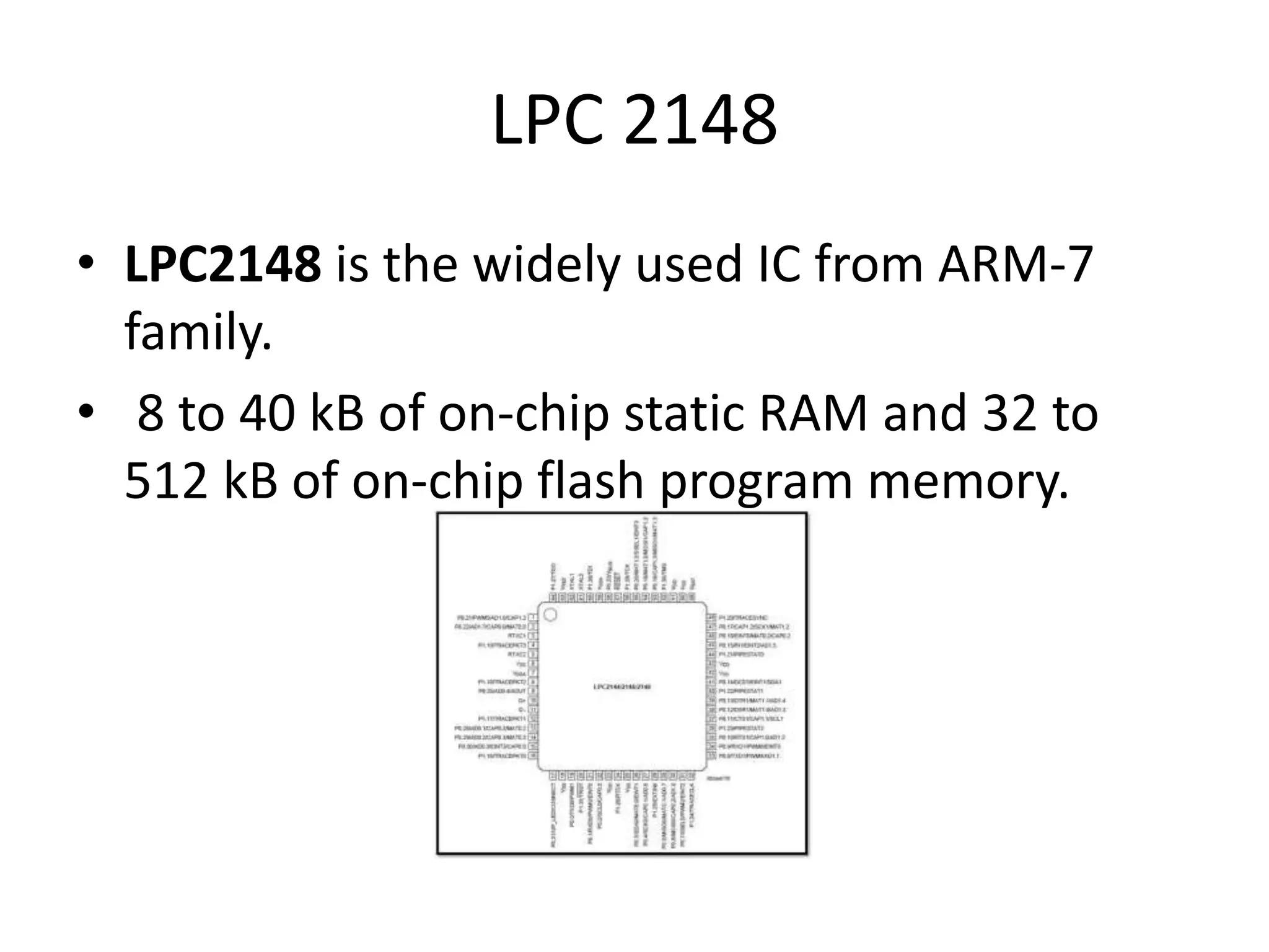
LPC 2148 • LPC2148is the widely used IC from ARM-7 family. • 8 to 40 kB of on-chip static RAM and 32 to 512 kB of on-chip flash program memory.
21.
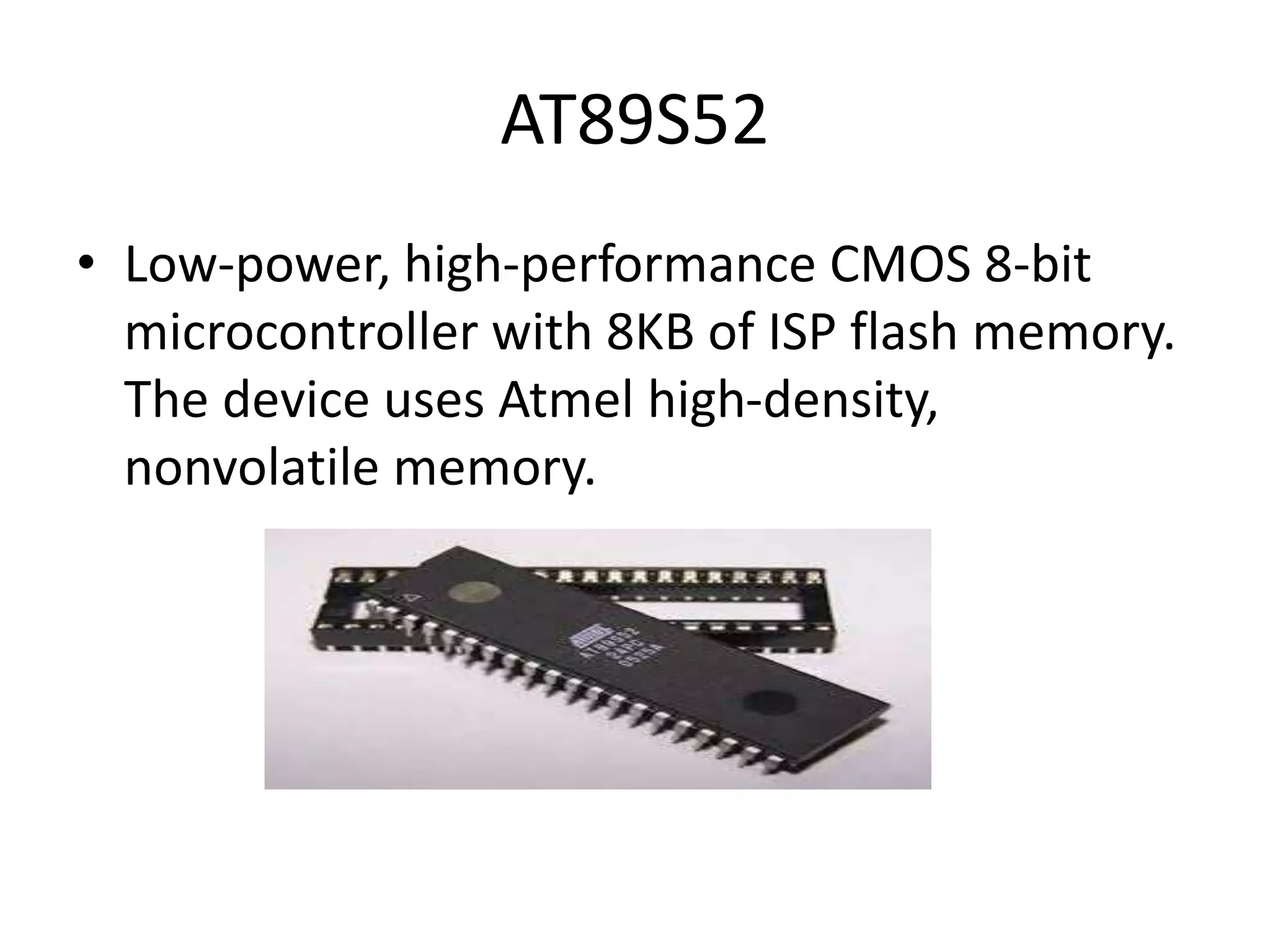
AT89S52 • Low-power, high-performanceCMOS 8-bit microcontroller with 8KB of ISP flash memory. The device uses Atmel high-density, nonvolatile memory.
22.
UART • A universalasynchronous receiver/transmitter, A UART is a computer hardware device that translates data between parallel and serial forms. UARTs are commonly used in conjunction with communication standards such as TIA (formerly EIA) RS-232, RS-422.
23.
GPIO • General-purpose input/output(GPIO) is a generic pin on an integrated circuit whose behaviour including whether it is an input or output pin is controllable by the user at run time.
24.
CURRENT DRIVER • Inelectronics, a driver is an electrical circuit or other electronic component used to control another circuit or component, such as a high- power transistor, liquid crystal display (LCD), and numerous others.
25.
Problem-solutions (ABOUT TRACK FAULTDETECTION) Let us discuss problem and solution. Previous, rail inspection methods include destructive techniques, such as coring, and non-destructive techniques, such as hammer sounding. But these methods just “cover limited space and have limited effectiveness in identifying the faults. Further non-destructive evaluation techniques for rail track inspection had developed. These technologies include visual inspection, ground penetrating radar (GPR), X-ray and laser light.
26.
• In orderto avoid this problem, we are using the crack detector robot, which detects the crack in the rails and gives an alarm.A robot is an apparently human automation, intelligent and obedient but impersonal machine
FUTURE SCOPE • Thegeographical positioning sensors are placed on the trains. These sensors send the train’s geographic location • Track fault detection solve the robot.
30.
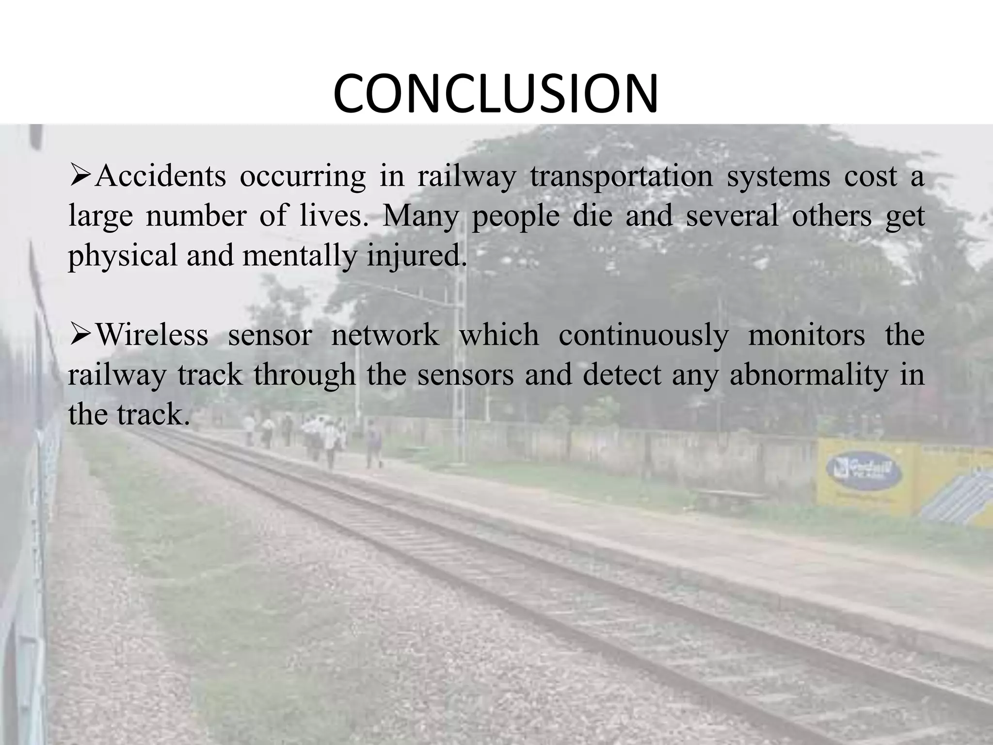
CONCLUSION Accidents occurring inrailway transportation systems cost a large number of lives. Many people die and several others get physical and mentally injured. Wireless sensor network which continuously monitors the railway track through the sensors and detect any abnormality in the track.
31.
REFERENCES • C. Campos-Castellanos,Y.Gharaibeh, P. Mudge *, V. Kappatos, “The application of long range ultrasonic testing (LRUT) For examination of hard to access areas on railway tracks”. IEEE Railway Condition Monitoring and NonDestructive Testing (RCM 2011) Nov 2011. • M. Singh, S.Singh1,J.Jaiswal, J. Hempshall “Autonomus rail track inspection using vision based system” .IEEE International Conference on Computational Intelligence for Homeland Security and Personal Safety pp 5659 .October 2006. • S.Zheng, X.An, X.Chai, L. Li “Railway track gauge inspection method based on computer vision” IEEE International Conference on Mechatronics and Automation, pp 1292-1296 year of 2012. • D.Hesse “Rail inspection using ultrasonic surface waves” Thesis ,Imperial College of London,2007