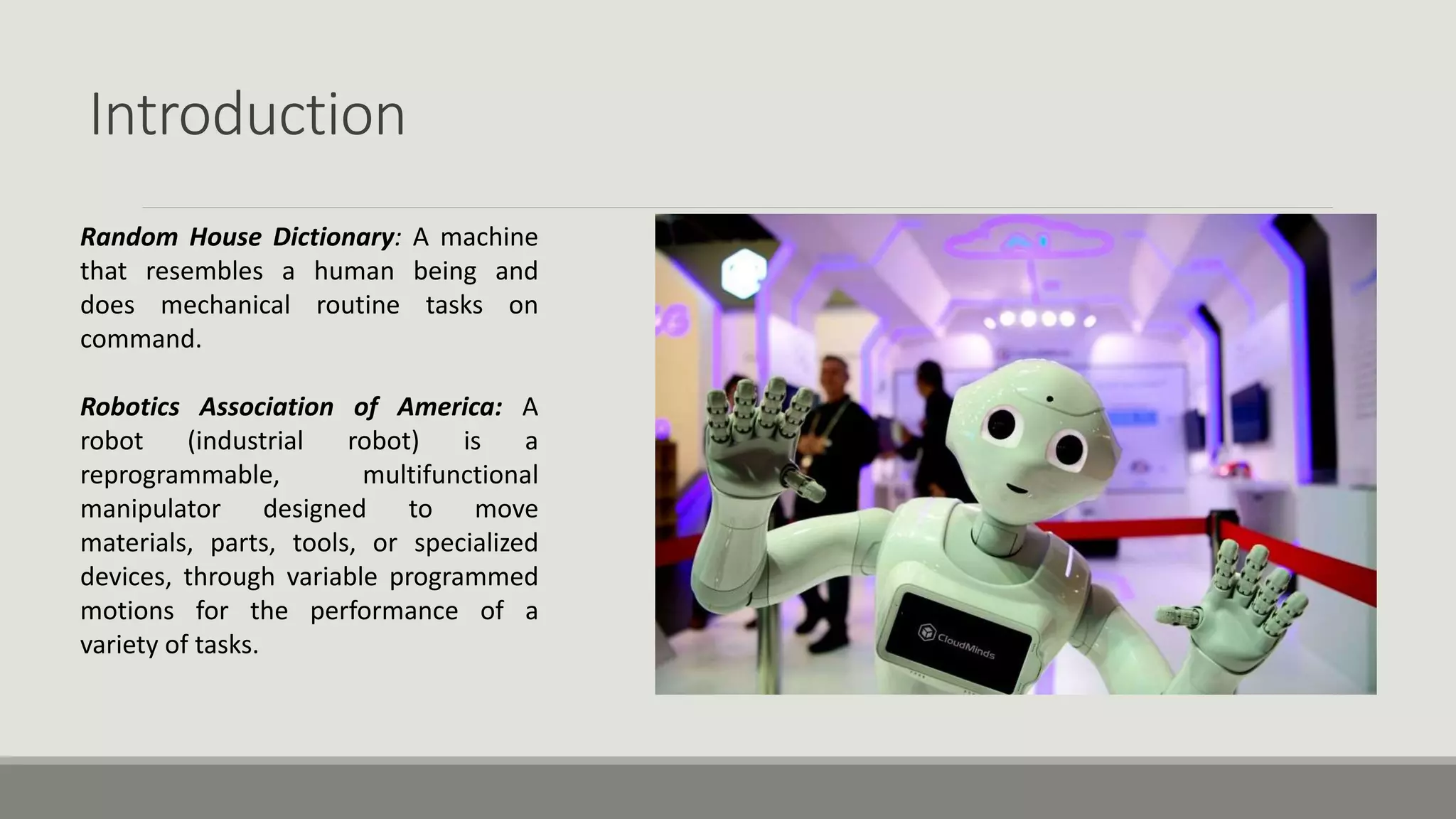
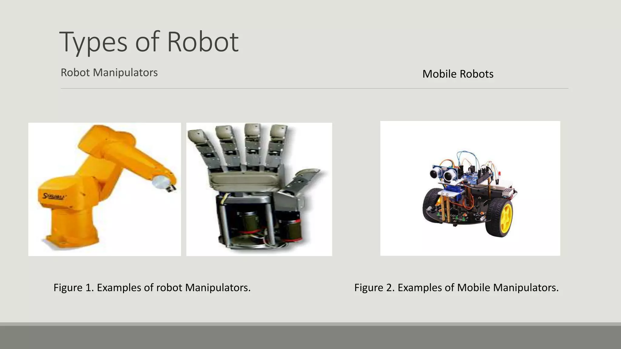
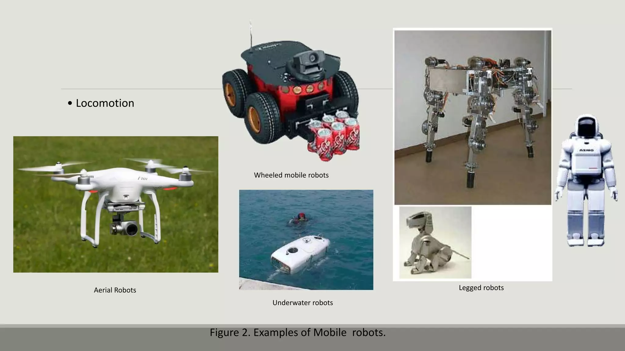
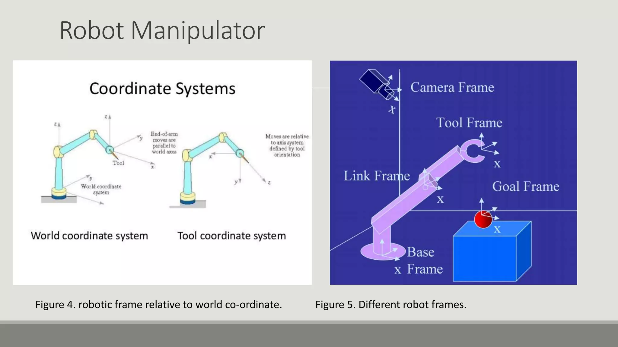
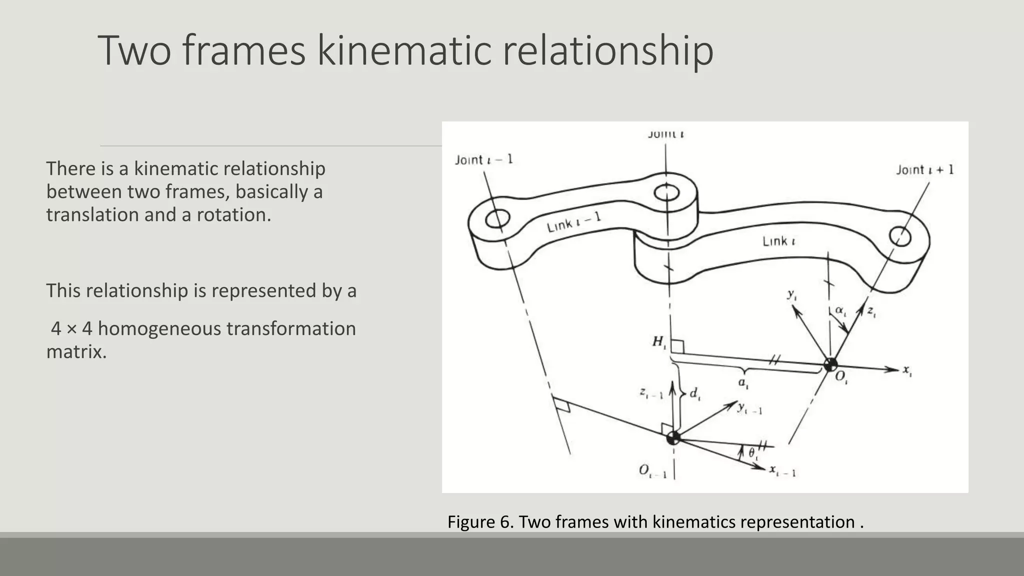
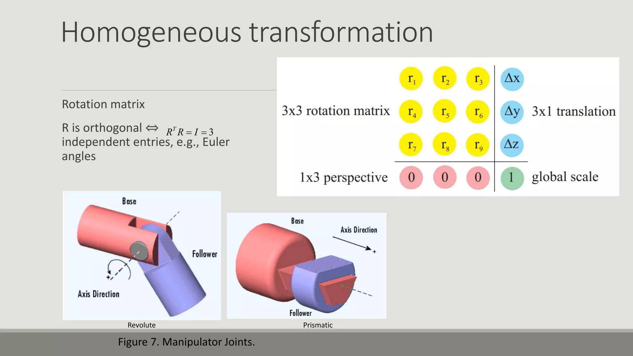
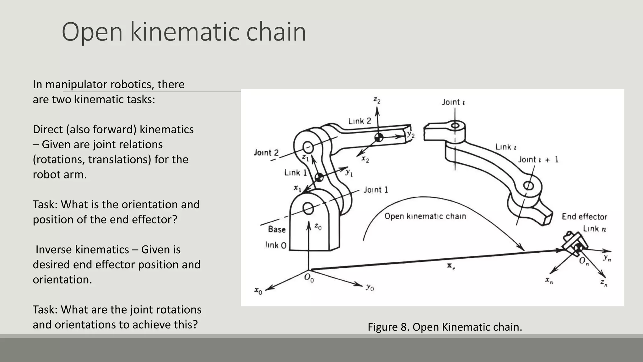
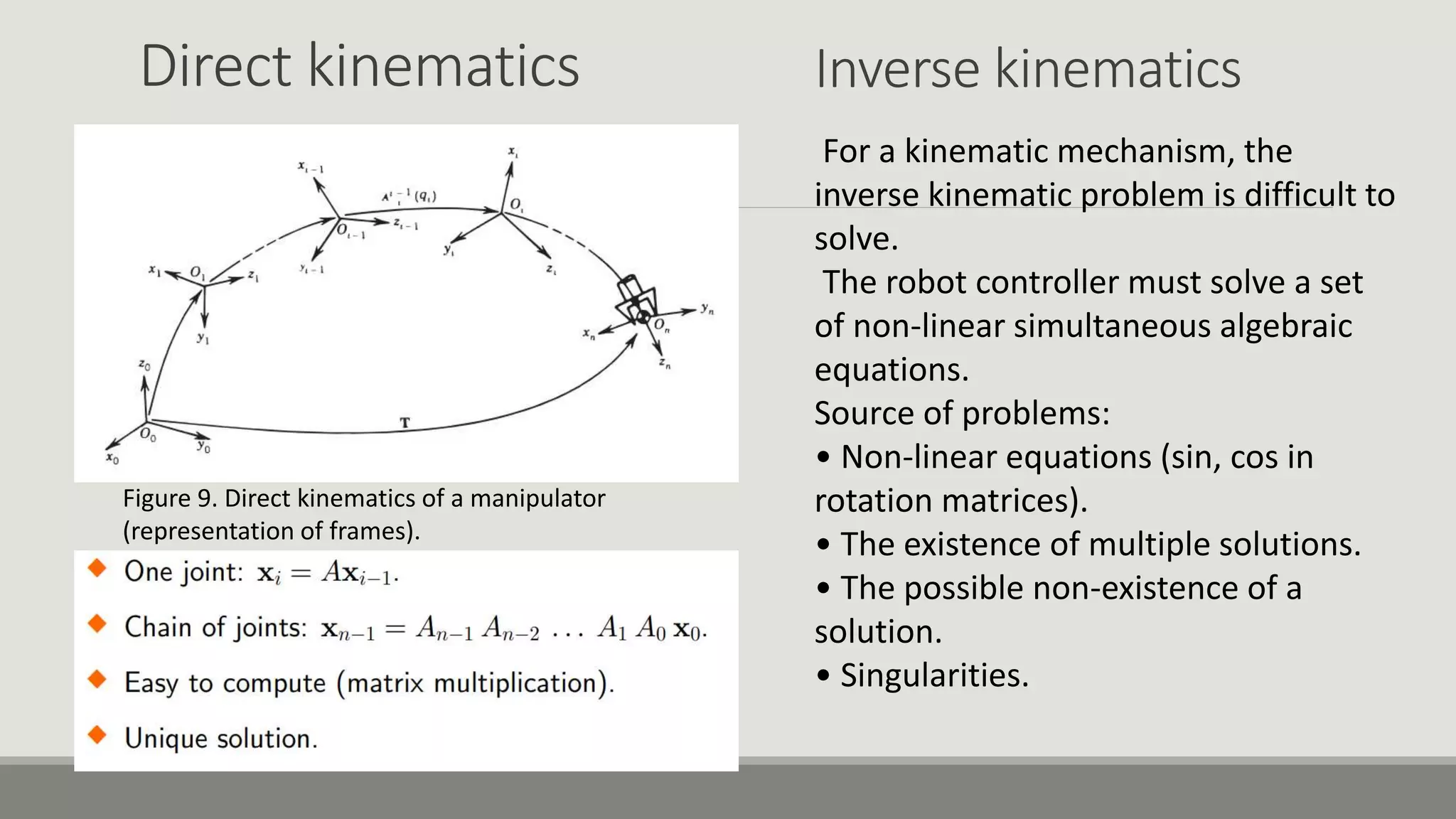
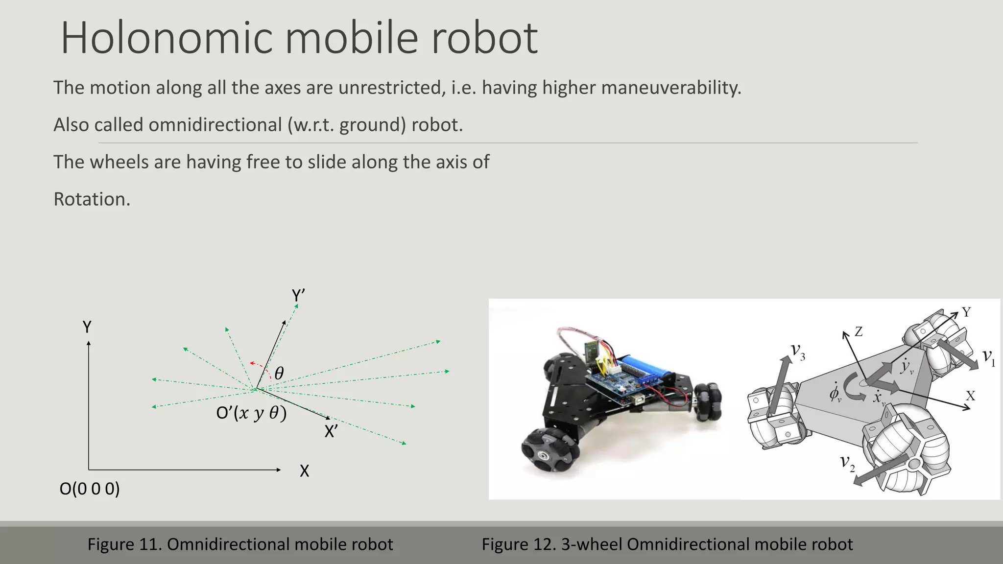
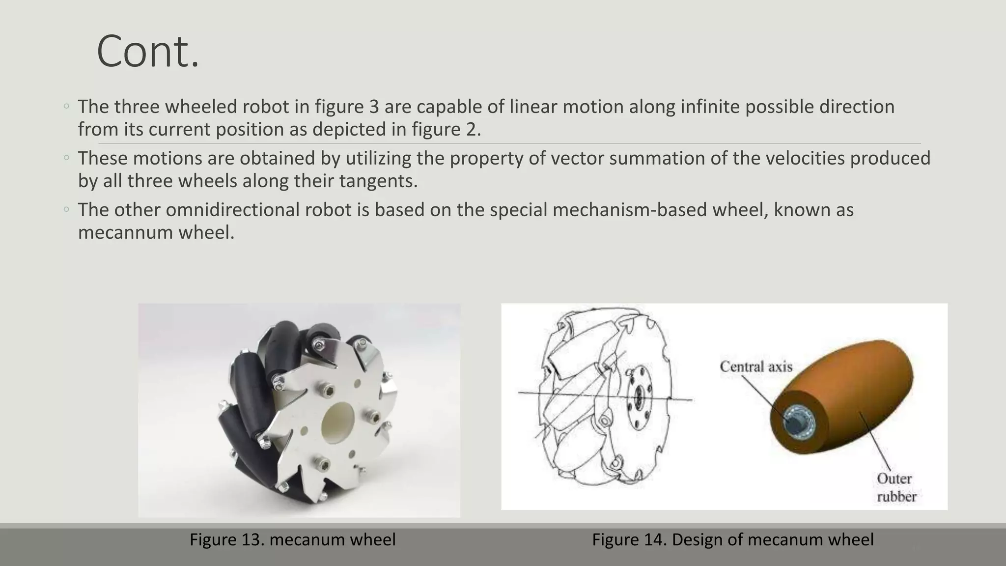
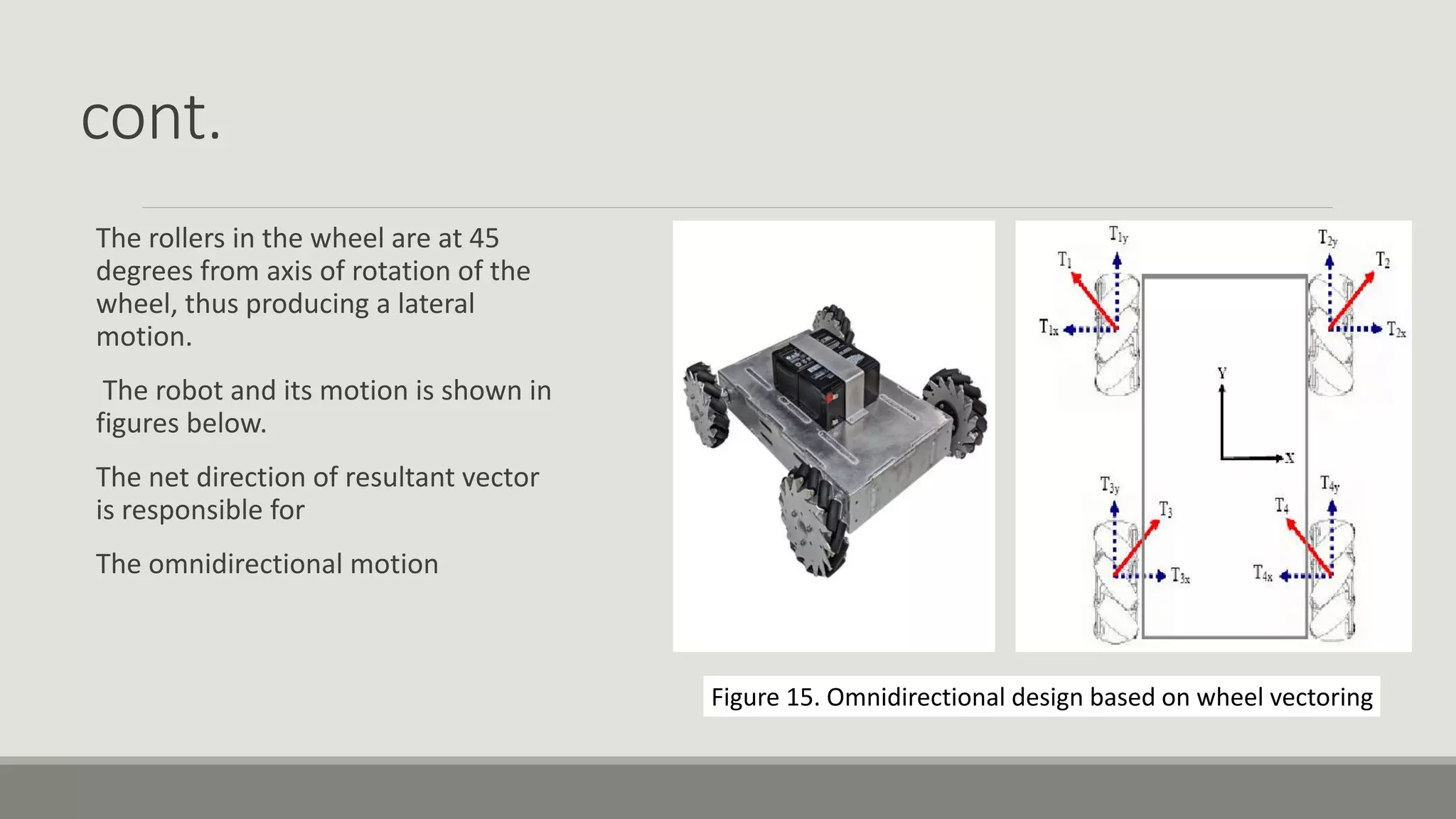
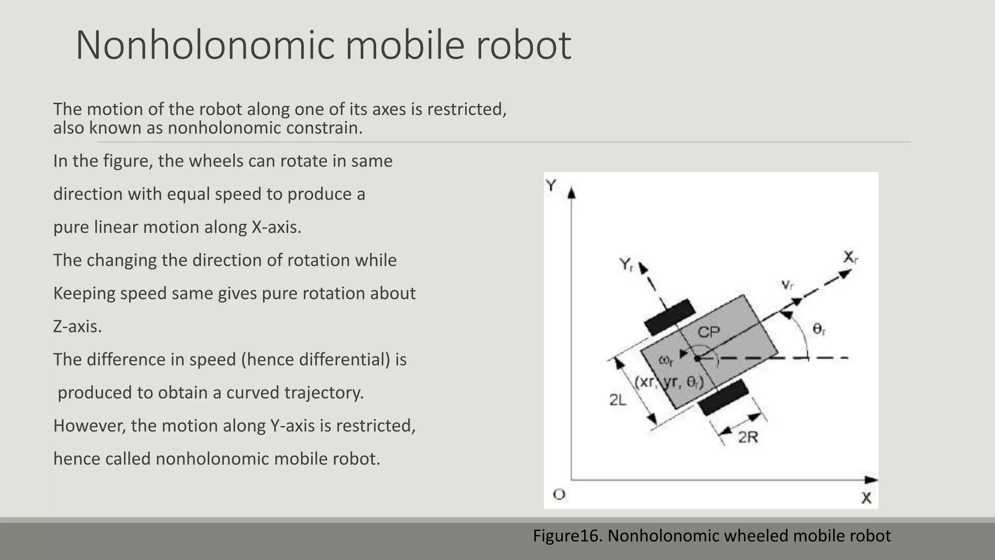
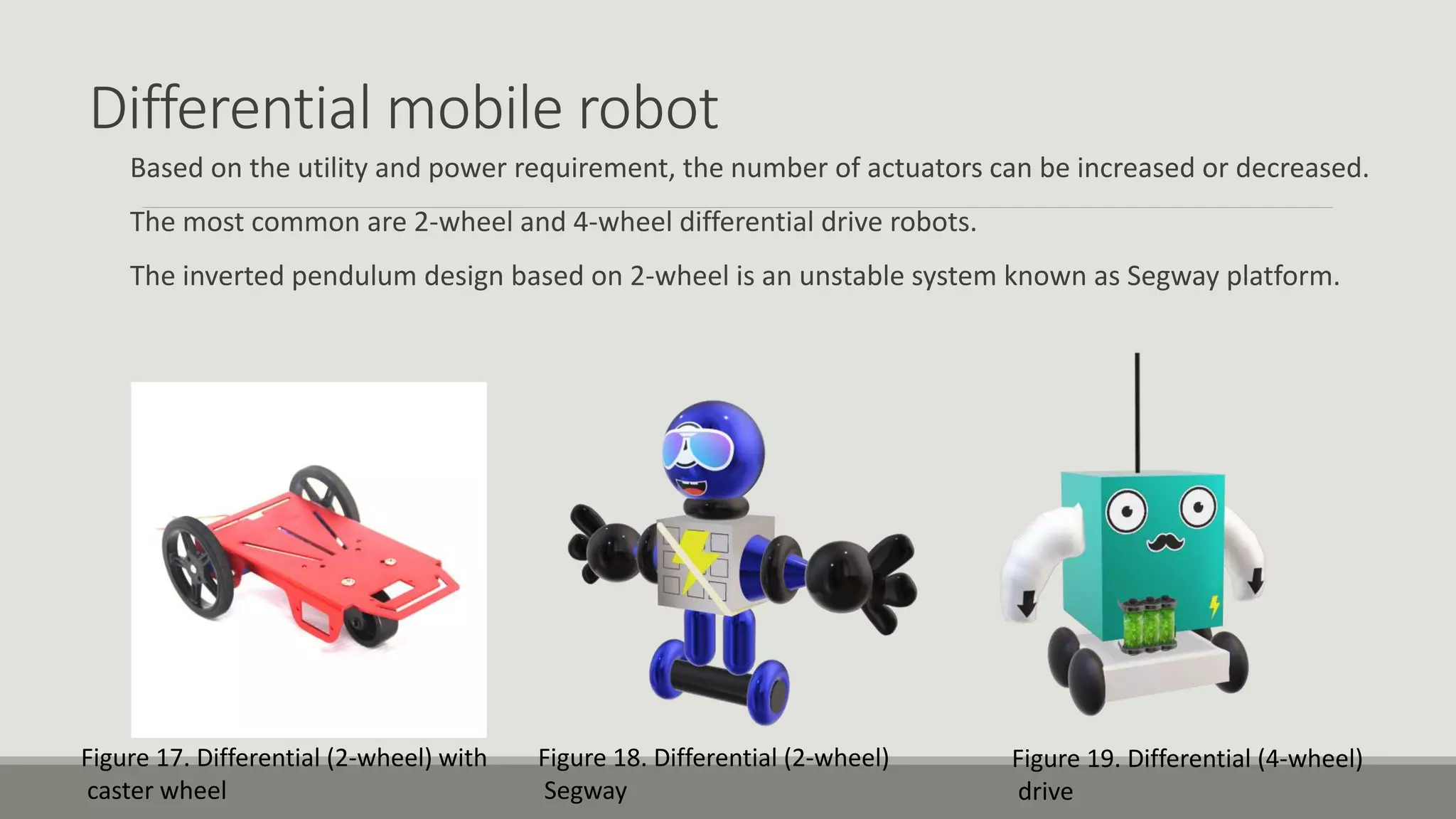
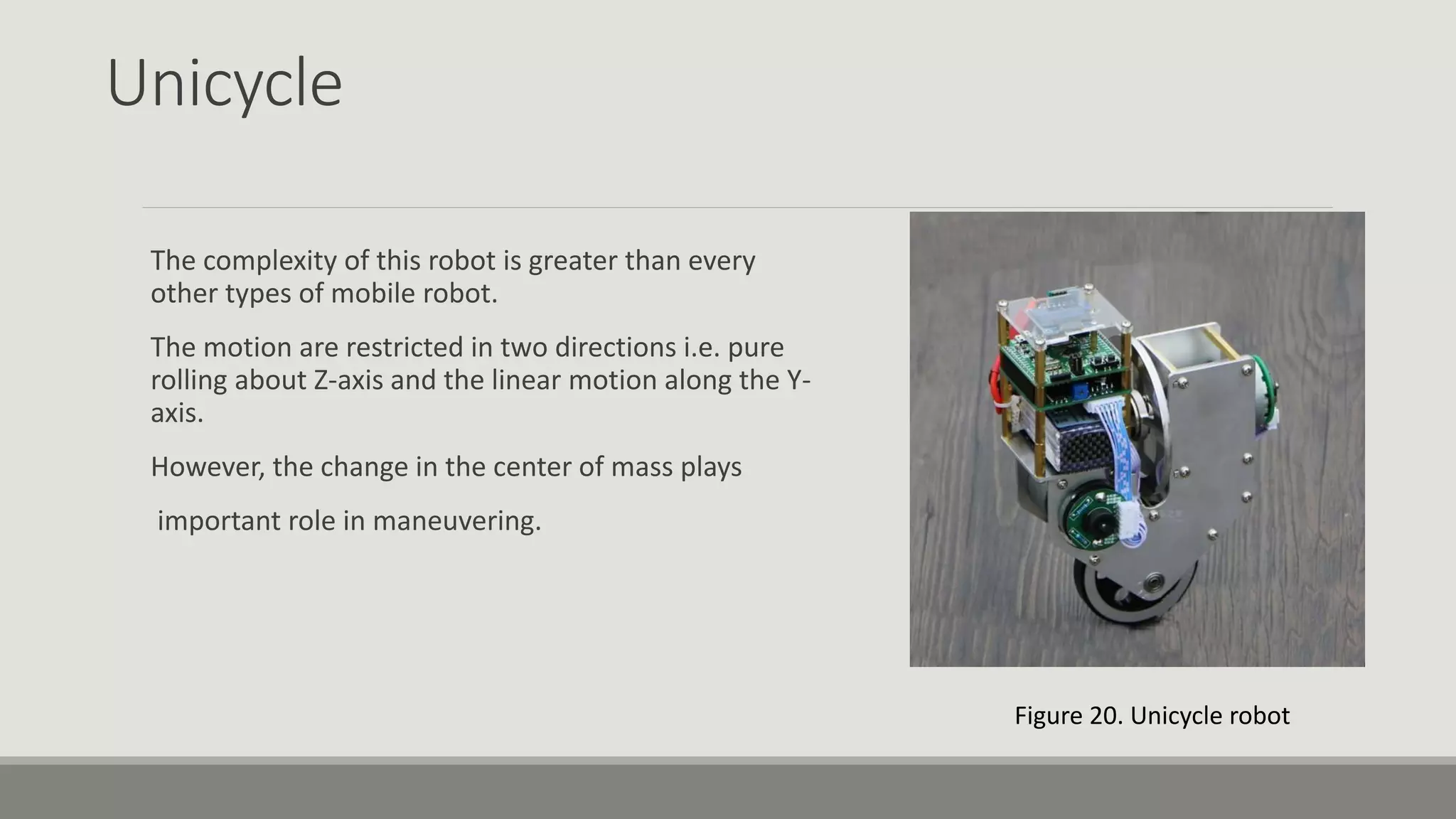
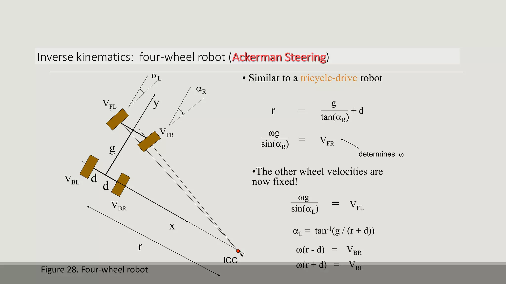
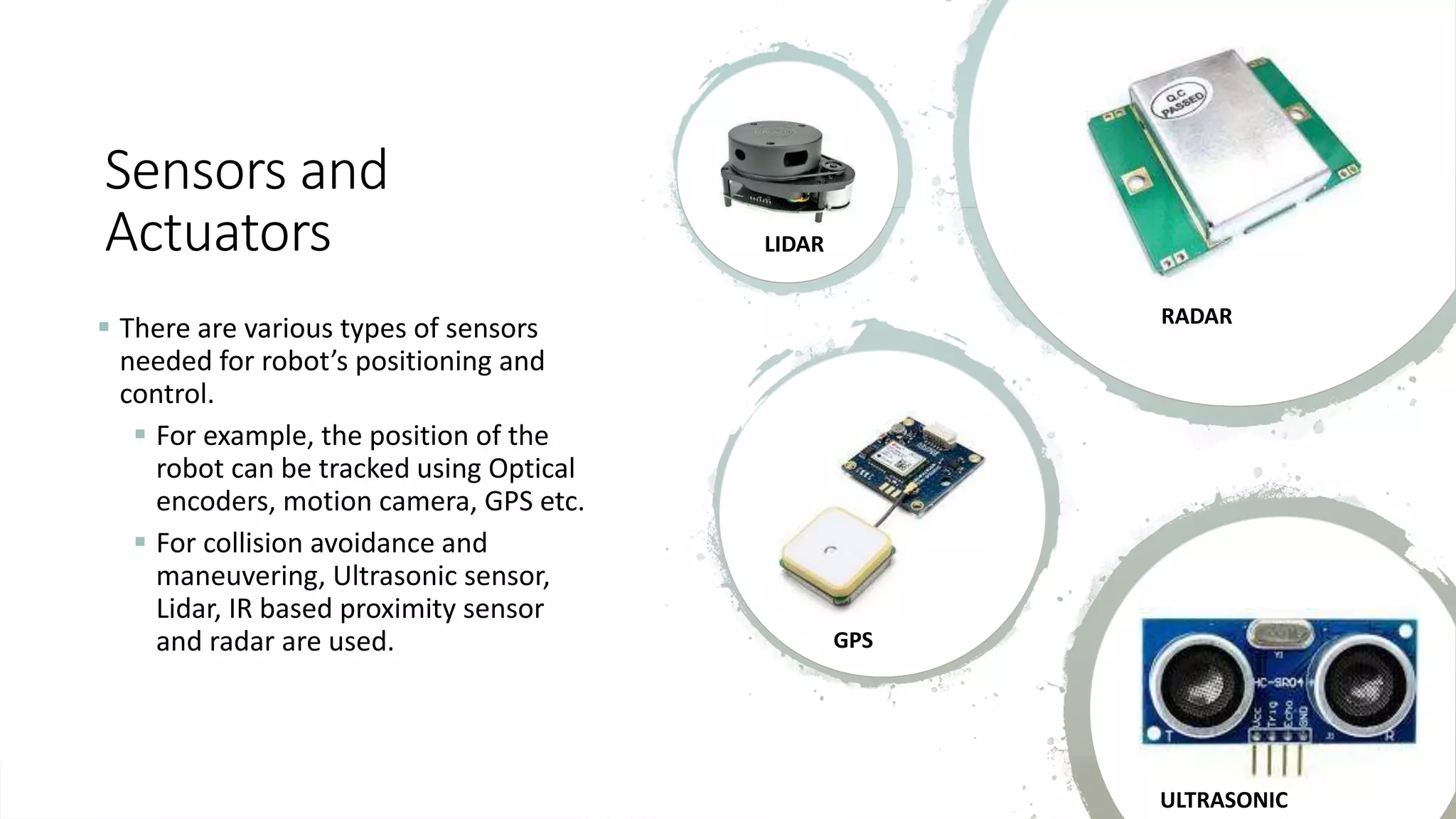
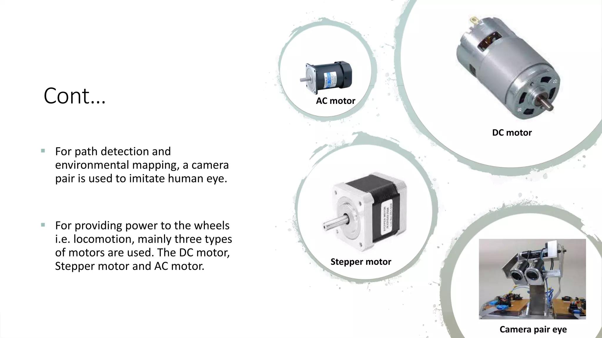
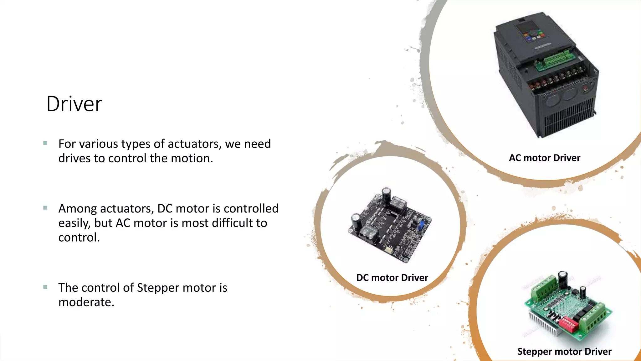
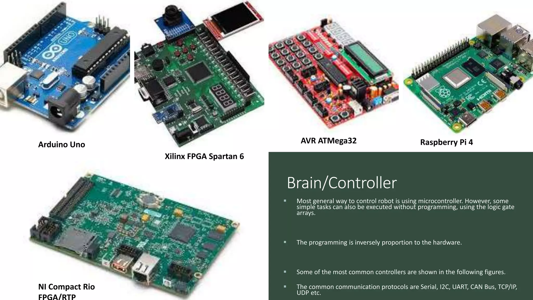
Nikhil Shrivas Assistant professor Department of Mechatronics Engg. Manipal University Jaipur AN I NTRODUCTI ON TO ROBOTICS Classification, Kinematics and hardware
Contents 1) Why robotics? 2) Types of robots. 3) Robot Manipulator 4) Mobile Robots 5) Sensors and actuators.
Introduction Random House Dictionary: A machine that resembles a human being and does mechanical routine tasks on command. Robotics Association of America: A robot (industrial robot) is a reprogrammable, multifunctional manipulator designed to move materials, parts, tools, or specialized devices, through variable programmed motions for the performance of a variety of tasks.
Types of Robot Robot Manipulators Mobile Robots Figure 1. Examples of robot Manipulators. Figure 2. Examples of Mobile Manipulators.
Legged robots Underwater robots Wheeled mobile robots Aerial Robots • Locomotion Figure 2. Examples of Mobile robots.
Robot Manipulator Figure 4. robotic frame relative to world co-ordinate. Figure 5. Different robot frames.
Two frames kinematic relationship There is a kinematic relationship between two frames, basically a translation and a rotation. This relationship is represented by a 4 × 4 homogeneous transformation matrix. Figure 6. Two frames with kinematics representation .
Homogeneous transformation Rotation matrix R is orthogonal ⇔ independent entries, e.g., Euler angles 3 T R R I   Revolute Prismatic Figure 7. Manipulator Joints.
Open kinematic chain In manipulator robotics, there are two kinematic tasks: Direct (also forward) kinematics – Given are joint relations (rotations, translations) for the robot arm. Task: What is the orientation and position of the end effector? Inverse kinematics – Given is desired end effector position and orientation. Task: What are the joint rotations and orientations to achieve this? Figure 8. Open Kinematic chain.
Direct kinematics Inverse kinematics For a kinematic mechanism, the inverse kinematic problem is difficult to solve. The robot controller must solve a set of non-linear simultaneous algebraic equations. Source of problems: • Non-linear equations (sin, cos in rotation matrices). • The existence of multiple solutions. • The possible non-existence of a solution. • Singularities. Figure 9. Direct kinematics of a manipulator (representation of frames).
Types of mobile robot The types are classified based on the actuation, locomotion and wheel configurations. Figure 10. Different types of mobile robots Mobile robot Holonomic 3-wheel 4-wheel Nonholonomic Differential 2-wheel Caster support Inverted pendulum 4-wheel Steering Tri-cycle Ackerman steering unicycle
Holonomic mobile robot The motion along all the axes are unrestricted, i.e. having higher maneuverability. Also called omnidirectional (w.r.t. ground) robot. The wheels are having free to slide along the axis of Rotation. X Y Y’ X’ 𝜃 O(0 0 0) O’(𝑥 𝑦 𝜃) Figure 12. 3-wheel Omnidirectional mobile robot Figure 11. Omnidirectional mobile robot
Cont. ◦ The three wheeled robot in figure 3 are capable of linear motion along infinite possible direction from its current position as depicted in figure 2. ◦ These motions are obtained by utilizing the property of vector summation of the velocities produced by all three wheels along their tangents. ◦ The other omnidirectional robot is based on the special mechanism-based wheel, known as mecannum wheel. 13 Figure 13. mecanum wheel Figure 14. Design of mecanum wheel
cont. The rollers in the wheel are at 45 degrees from axis of rotation of the wheel, thus producing a lateral motion. The robot and its motion is shown in figures below. The net direction of resultant vector is responsible for The omnidirectional motion Figure 15. Omnidirectional design based on wheel vectoring
Nonholonomic mobile robot The motion of the robot along one of its axes is restricted, also known as nonholonomic constrain. In the figure, the wheels can rotate in same direction with equal speed to produce a pure linear motion along X-axis. The changing the direction of rotation while Keeping speed same gives pure rotation about Z-axis. The difference in speed (hence differential) is produced to obtain a curved trajectory. However, the motion along Y-axis is restricted, hence called nonholonomic mobile robot. Figure16. Nonholonomic wheeled mobile robot
Differential mobile robot Based on the utility and power requirement, the number of actuators can be increased or decreased. The most common are 2-wheel and 4-wheel differential drive robots. The inverted pendulum design based on 2-wheel is an unstable system known as Segway platform. Figure 19. Differential (4-wheel) drive Figure 17. Differential (2-wheel) with caster wheel Figure 18. Differential (2-wheel) Segway
Unicycle The complexity of this robot is greater than every other types of mobile robot. The motion are restricted in two directions i.e. pure rolling about Z-axis and the linear motion along the Y- axis. However, the change in the center of mass plays important role in maneuvering. Figure 20. Unicycle robot
Steering based robot The steering can be applied to single front wheel (in tri-cycle), double front wheel (Ackerman steering). The robot’s curved motion is obtained about a point in the plane also known as instantaneous Centre of curvature/rotation (ICC/ICR). Figure 21. tri-cycle robot Figure 22. Ackerman steering robot
Mobile Robot Maneuverability  The maneuverability of a mobile robot is the combination  of the mobility available based on the sliding constraints  plus additional freedom contributed by the steering  Three wheels is sufficient for static stability  additional wheels need to be synchronized  this is also the case for some arrangements with three wheels  It can be derived using the equation seen before  Degree of mobility  Degree of steerability  Robots maneuverability m s M m s
The basic types of 3-wheel robot Based on different designs, the robot’s ability to perform motion i.e. its maneuverability is obtained for tri-cycle robot. Figure 23. Maneuverability of tricycle mobile robot with different designs
Locomotion of mobile robot The locomotion is defined by the number of actuators, types of wheels and design of the robot.  Assumptions in wheels  Movement on a horizontal plane  Point contact of the wheels  Wheels not deformable  Pure rolling (vc = 0 at contact point)  No slipping, skidding or sliding  No friction for rotation around contact point  Steering axes orthogonal to the surface  Wheels connected by rigid frame (chassis)  .r v YR XR  P YI XI Figure 24. Mobile robot in 2-D plane
Kinematics of Differential drive 1) Specify system measurements 2) Consider possible coordinate systems 3) each wheel must be traveling at the same angular velocity around the ICC 4) Determine the robot’s speed around the ICC and then linear velocity 5) Determine the point (the radius) around which the robot is turning. w(R+d) = VL w(R-d) = VR Thus, w = ( VR - VL ) / 2d R = 2d ( VR + VL ) / ( VR - VL ) So, the robot’s velocity is V = wR = ( VR + VL ) / 2 Figure 25. ICC“ instantaneous center of curvature” x y VR VL 2d ICC R w V
Figure 26. Nomad 200 • Wheel velocities are linearly related with actuators speed. • Have to obtain position and orientation w.r.t. given velocities Vrobot = Vwheels wrobot = wwheels x(t) =  Vwheels(t) cos((t)) dt y(t) =  Vwheels(t) sin((t)) dt (t) =  w(t) dt position velocity y x  w Vwheels ICC at  Forward kinematics, velocity and position
Inverse kinematics: differential drive Key question: Given a desired position or velocity, what can we do to achieve it? Figure 27(a). starting position Figure 27 (b). final position x VR(t) VL (t) y 𝑃𝑖
Turn so that the wheels are parallel to the line between the original and final position of the robot origin i.e. line connection the robot and desired point. Drive straight until the robot’s origin coincides with the destination. Rotate again in order to achieve the desired final orientation. Usual approach: decompose the problem and control only a few DOF at a time -VL (t) = VR (t) = Vmax VL (t) = VR (t) = Vmax VL (t) t VR (t) -VL (t) = VR (t) = Vmax Figure 28. set of motion of actuators
Inverse kinematics: four-wheel robot (Ackerman Steering) VBL VBR VFR VFL x y ICC aR aL • Similar to a tricycle-drive robot wg r g d d VFR = sin(aR) r = g tan(aR) + d determines w Figure 28. Four-wheel robot •The other wheel velocities are now fixed! wg VFL = sin(aL) aL = tan-1(g / (r + d)) w(r - d) = VBR w(r + d) = VBL
cont. After finding out the front and real wheel velocities, the net velocities for the differential mode can be obtained as 𝑉𝐿 𝑡 = 𝑉𝐹𝐿 + 𝑉𝐵𝐿 and 𝑉𝑅 𝑡 = 𝑉𝐹𝑅 + 𝑉𝐵𝑅 The obtained left and right velocities can be converted to respective wheels angular velocities. With the help of proper actuation and control, the robot can be maneuvered easily to obtain desired position. Inverse kinematics: four-wheel robot (Ackerman Steering)
Sensors and Actuators  There are various types of sensors needed for robot’s positioning and control.  For example, the position of the robot can be tracked using Optical encoders, motion camera, GPS etc.  For collision avoidance and maneuvering, Ultrasonic sensor, Lidar, IR based proximity sensor and radar are used. LIDAR RADAR GPS ULTRASONIC
Cont…  For path detection and environmental mapping, a camera pair is used to imitate human eye.  For providing power to the wheels i.e. locomotion, mainly three types of motors are used. The DC motor, Stepper motor and AC motor. AC motor DC motor Stepper motor Camera pair eye
Driver  For various types of actuators, we need drives to control the motion.  Among actuators, DC motor is controlled easily, but AC motor is most difficult to control.  The control of Stepper motor is moderate. AC motor Driver DC motor Driver Stepper motor Driver
Brain/Controller  Most general way to control robot is using microcontroller. However, some simple tasks can also be executed without programming, using the logic gate arrays.  The programming is inversely proportion to the hardware.  Some of the most common controllers are shown in the following figures.  The common communication protocols are Serial, I2C, UART, CAN Bus, TCP/IP, UDP etc. Arduino Uno Xilinx FPGA Spartan 6 AVR ATMega32 Raspberry Pi 4 NI Compact Rio
Thank you

An introduction to robotics classification, kinematics and hardware

  • 1.
    Nikhil Shrivas Assistant professor Departmentof Mechatronics Engg. Manipal University Jaipur AN I NTRODUCTI ON TO ROBOTICS Classification, Kinematics and hardware
  • 2.
    Contents 1) Why robotics? 2)Types of robots. 3) Robot Manipulator 4) Mobile Robots 5) Sensors and actuators.
  • 3.
    Introduction Random House Dictionary:A machine that resembles a human being and does mechanical routine tasks on command. Robotics Association of America: A robot (industrial robot) is a reprogrammable, multifunctional manipulator designed to move materials, parts, tools, or specialized devices, through variable programmed motions for the performance of a variety of tasks.
  • 4.
    Types of Robot RobotManipulators Mobile Robots Figure 1. Examples of robot Manipulators. Figure 2. Examples of Mobile Manipulators.
  • 5.
    Legged robots Underwater robots Wheeledmobile robots Aerial Robots • Locomotion Figure 2. Examples of Mobile robots.
  • 6.
    Robot Manipulator Figure 4.robotic frame relative to world co-ordinate. Figure 5. Different robot frames.
  • 7.
    Two frames kinematicrelationship There is a kinematic relationship between two frames, basically a translation and a rotation. This relationship is represented by a 4 × 4 homogeneous transformation matrix. Figure 6. Two frames with kinematics representation .
  • 8.
    Homogeneous transformation Rotation matrix Ris orthogonal ⇔ independent entries, e.g., Euler angles 3 T R R I   Revolute Prismatic Figure 7. Manipulator Joints.
  • 9.
    Open kinematic chain Inmanipulator robotics, there are two kinematic tasks: Direct (also forward) kinematics – Given are joint relations (rotations, translations) for the robot arm. Task: What is the orientation and position of the end effector? Inverse kinematics – Given is desired end effector position and orientation. Task: What are the joint rotations and orientations to achieve this? Figure 8. Open Kinematic chain.
  • 10.
    Direct kinematics Inversekinematics For a kinematic mechanism, the inverse kinematic problem is difficult to solve. The robot controller must solve a set of non-linear simultaneous algebraic equations. Source of problems: • Non-linear equations (sin, cos in rotation matrices). • The existence of multiple solutions. • The possible non-existence of a solution. • Singularities. Figure 9. Direct kinematics of a manipulator (representation of frames).
  • 11.
    Types of mobilerobot The types are classified based on the actuation, locomotion and wheel configurations. Figure 10. Different types of mobile robots Mobile robot Holonomic 3-wheel 4-wheel Nonholonomic Differential 2-wheel Caster support Inverted pendulum 4-wheel Steering Tri-cycle Ackerman steering unicycle
  • 12.
    Holonomic mobile robot Themotion along all the axes are unrestricted, i.e. having higher maneuverability. Also called omnidirectional (w.r.t. ground) robot. The wheels are having free to slide along the axis of Rotation. X Y Y’ X’ 𝜃 O(0 0 0) O’(𝑥 𝑦 𝜃) Figure 12. 3-wheel Omnidirectional mobile robot Figure 11. Omnidirectional mobile robot
  • 13.
    Cont. ◦ The threewheeled robot in figure 3 are capable of linear motion along infinite possible direction from its current position as depicted in figure 2. ◦ These motions are obtained by utilizing the property of vector summation of the velocities produced by all three wheels along their tangents. ◦ The other omnidirectional robot is based on the special mechanism-based wheel, known as mecannum wheel. 13 Figure 13. mecanum wheel Figure 14. Design of mecanum wheel
  • 14.
    cont. The rollers inthe wheel are at 45 degrees from axis of rotation of the wheel, thus producing a lateral motion. The robot and its motion is shown in figures below. The net direction of resultant vector is responsible for The omnidirectional motion Figure 15. Omnidirectional design based on wheel vectoring
  • 15.
    Nonholonomic mobile robot Themotion of the robot along one of its axes is restricted, also known as nonholonomic constrain. In the figure, the wheels can rotate in same direction with equal speed to produce a pure linear motion along X-axis. The changing the direction of rotation while Keeping speed same gives pure rotation about Z-axis. The difference in speed (hence differential) is produced to obtain a curved trajectory. However, the motion along Y-axis is restricted, hence called nonholonomic mobile robot. Figure16. Nonholonomic wheeled mobile robot
  • 16.
    Differential mobile robot Basedon the utility and power requirement, the number of actuators can be increased or decreased. The most common are 2-wheel and 4-wheel differential drive robots. The inverted pendulum design based on 2-wheel is an unstable system known as Segway platform. Figure 19. Differential (4-wheel) drive Figure 17. Differential (2-wheel) with caster wheel Figure 18. Differential (2-wheel) Segway
  • 17.
    Unicycle The complexity ofthis robot is greater than every other types of mobile robot. The motion are restricted in two directions i.e. pure rolling about Z-axis and the linear motion along the Y- axis. However, the change in the center of mass plays important role in maneuvering. Figure 20. Unicycle robot
  • 18.
    Steering based robot Thesteering can be applied to single front wheel (in tri-cycle), double front wheel (Ackerman steering). The robot’s curved motion is obtained about a point in the plane also known as instantaneous Centre of curvature/rotation (ICC/ICR). Figure 21. tri-cycle robot Figure 22. Ackerman steering robot
  • 19.
    Mobile Robot Maneuverability The maneuverability of a mobile robot is the combination  of the mobility available based on the sliding constraints  plus additional freedom contributed by the steering  Three wheels is sufficient for static stability  additional wheels need to be synchronized  this is also the case for some arrangements with three wheels  It can be derived using the equation seen before  Degree of mobility  Degree of steerability  Robots maneuverability m s M m s
  • 20.
    The basic typesof 3-wheel robot Based on different designs, the robot’s ability to perform motion i.e. its maneuverability is obtained for tri-cycle robot. Figure 23. Maneuverability of tricycle mobile robot with different designs
  • 21.
    Locomotion of mobilerobot The locomotion is defined by the number of actuators, types of wheels and design of the robot.  Assumptions in wheels  Movement on a horizontal plane  Point contact of the wheels  Wheels not deformable  Pure rolling (vc = 0 at contact point)  No slipping, skidding or sliding  No friction for rotation around contact point  Steering axes orthogonal to the surface  Wheels connected by rigid frame (chassis)  .r v YR XR  P YI XI Figure 24. Mobile robot in 2-D plane
  • 22.
    Kinematics of Differentialdrive 1) Specify system measurements 2) Consider possible coordinate systems 3) each wheel must be traveling at the same angular velocity around the ICC 4) Determine the robot’s speed around the ICC and then linear velocity 5) Determine the point (the radius) around which the robot is turning. w(R+d) = VL w(R-d) = VR Thus, w = ( VR - VL ) / 2d R = 2d ( VR + VL ) / ( VR - VL ) So, the robot’s velocity is V = wR = ( VR + VL ) / 2 Figure 25. ICC“ instantaneous center of curvature” x y VR VL 2d ICC R w V
  • 23.
    Figure 26. Nomad200 • Wheel velocities are linearly related with actuators speed. • Have to obtain position and orientation w.r.t. given velocities Vrobot = Vwheels wrobot = wwheels x(t) =  Vwheels(t) cos((t)) dt y(t) =  Vwheels(t) sin((t)) dt (t) =  w(t) dt position velocity y x  w Vwheels ICC at  Forward kinematics, velocity and position
  • 24.
    Inverse kinematics: differentialdrive Key question: Given a desired position or velocity, what can we do to achieve it? Figure 27(a). starting position Figure 27 (b). final position x VR(t) VL (t) y 𝑃𝑖
  • 25.
    Turn so thatthe wheels are parallel to the line between the original and final position of the robot origin i.e. line connection the robot and desired point. Drive straight until the robot’s origin coincides with the destination. Rotate again in order to achieve the desired final orientation. Usual approach: decompose the problem and control only a few DOF at a time -VL (t) = VR (t) = Vmax VL (t) = VR (t) = Vmax VL (t) t VR (t) -VL (t) = VR (t) = Vmax Figure 28. set of motion of actuators
  • 26.
    Inverse kinematics: four-wheelrobot (Ackerman Steering) VBL VBR VFR VFL x y ICC aR aL • Similar to a tricycle-drive robot wg r g d d VFR = sin(aR) r = g tan(aR) + d determines w Figure 28. Four-wheel robot •The other wheel velocities are now fixed! wg VFL = sin(aL) aL = tan-1(g / (r + d)) w(r - d) = VBR w(r + d) = VBL
  • 27.
    cont. After finding outthe front and real wheel velocities, the net velocities for the differential mode can be obtained as 𝑉𝐿 𝑡 = 𝑉𝐹𝐿 + 𝑉𝐵𝐿 and 𝑉𝑅 𝑡 = 𝑉𝐹𝑅 + 𝑉𝐵𝑅 The obtained left and right velocities can be converted to respective wheels angular velocities. With the help of proper actuation and control, the robot can be maneuvered easily to obtain desired position. Inverse kinematics: four-wheel robot (Ackerman Steering)
  • 28.
    Sensors and Actuators  Thereare various types of sensors needed for robot’s positioning and control.  For example, the position of the robot can be tracked using Optical encoders, motion camera, GPS etc.  For collision avoidance and maneuvering, Ultrasonic sensor, Lidar, IR based proximity sensor and radar are used. LIDAR RADAR GPS ULTRASONIC
  • 29.
    Cont…  For pathdetection and environmental mapping, a camera pair is used to imitate human eye.  For providing power to the wheels i.e. locomotion, mainly three types of motors are used. The DC motor, Stepper motor and AC motor. AC motor DC motor Stepper motor Camera pair eye
  • 30.
    Driver  For varioustypes of actuators, we need drives to control the motion.  Among actuators, DC motor is controlled easily, but AC motor is most difficult to control.  The control of Stepper motor is moderate. AC motor Driver DC motor Driver Stepper motor Driver
  • 31.
    Brain/Controller  Most generalway to control robot is using microcontroller. However, some simple tasks can also be executed without programming, using the logic gate arrays.  The programming is inversely proportion to the hardware.  Some of the most common controllers are shown in the following figures.  The common communication protocols are Serial, I2C, UART, CAN Bus, TCP/IP, UDP etc. Arduino Uno Xilinx FPGA Spartan 6 AVR ATMega32 Raspberry Pi 4 NI Compact Rio
  • 32.