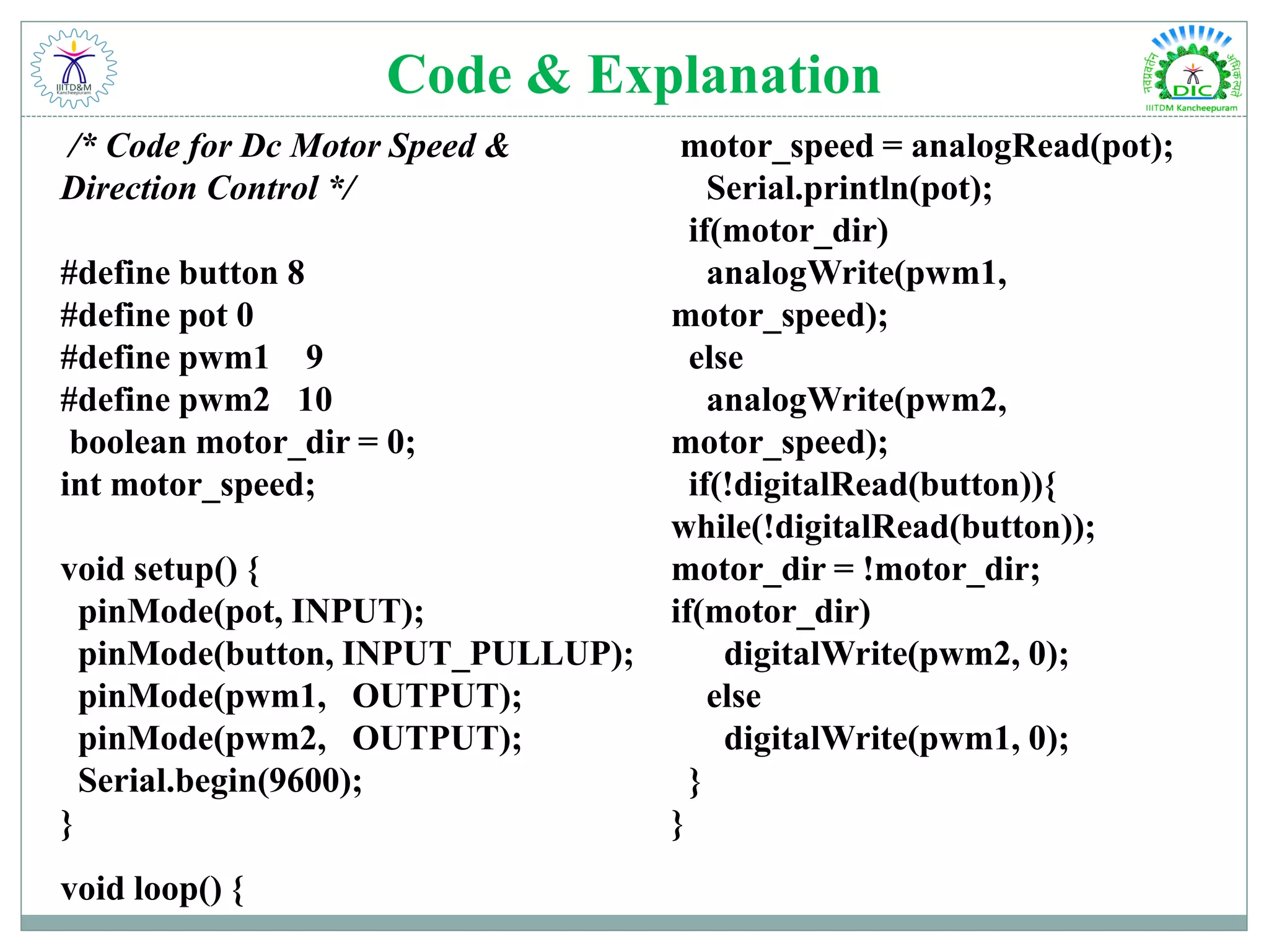
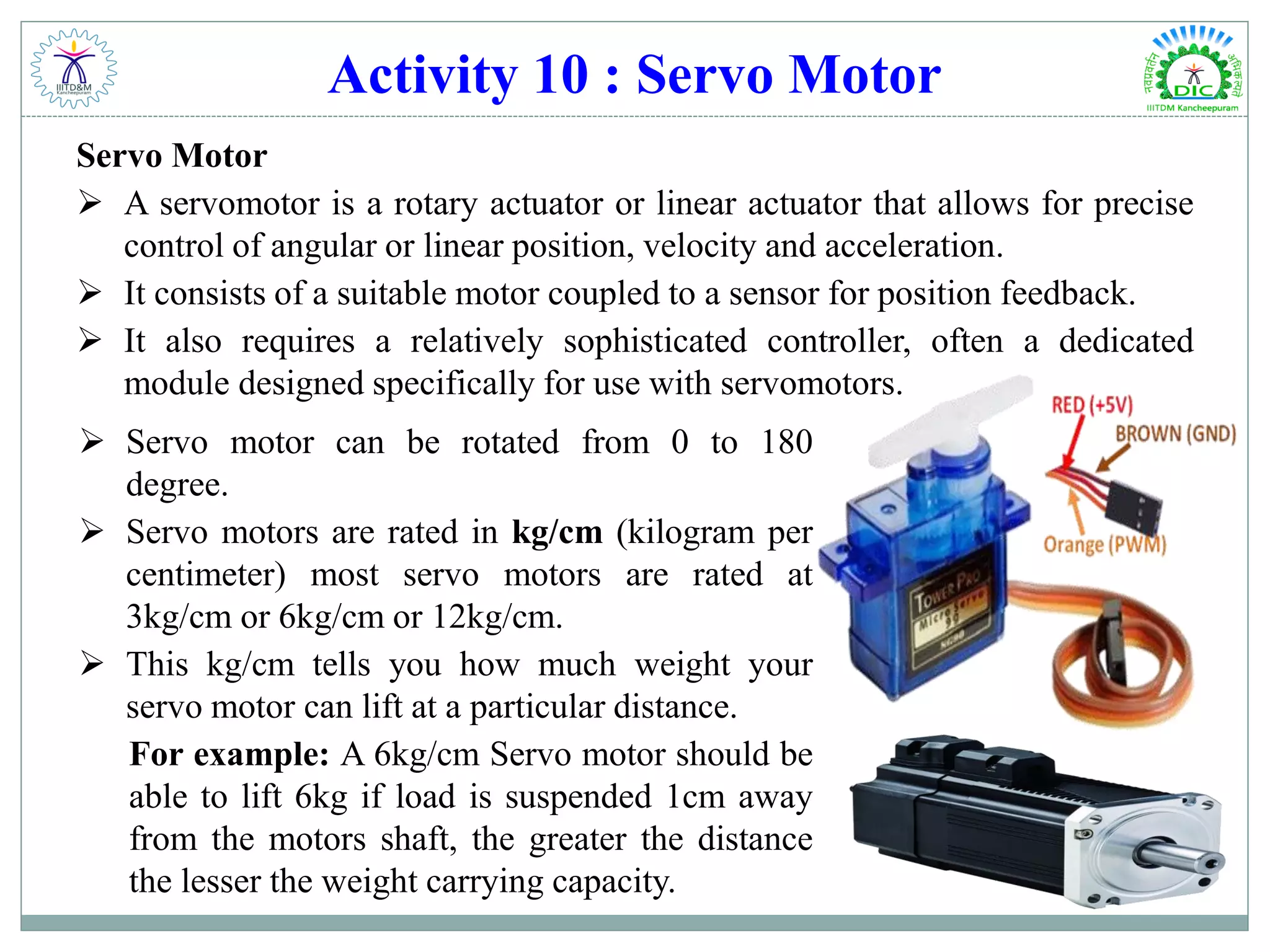
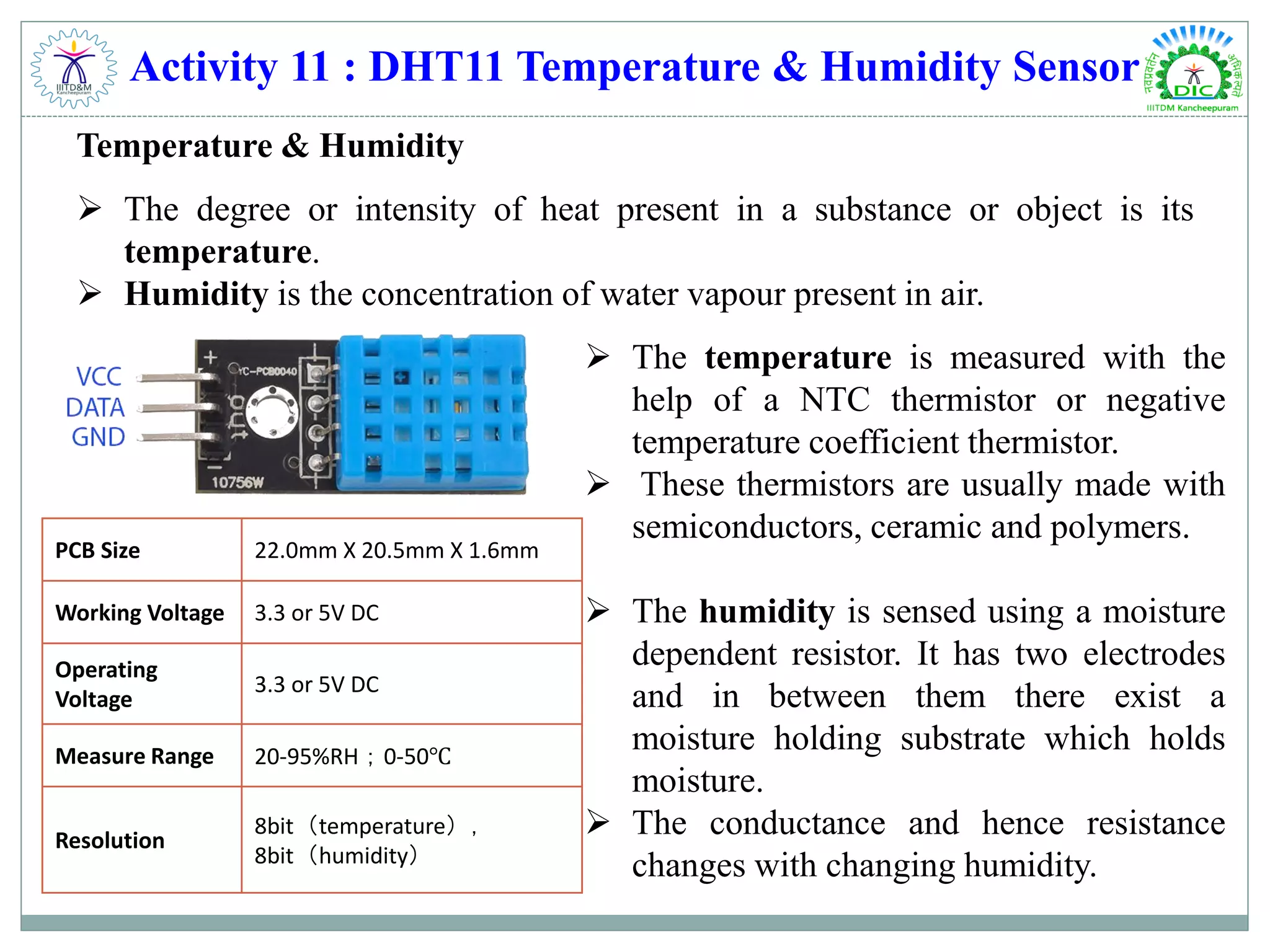
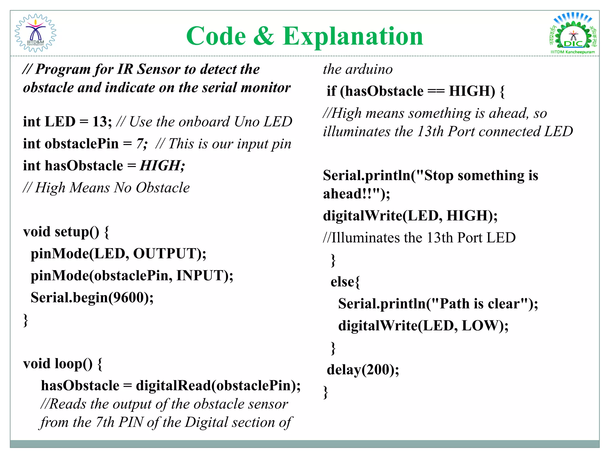
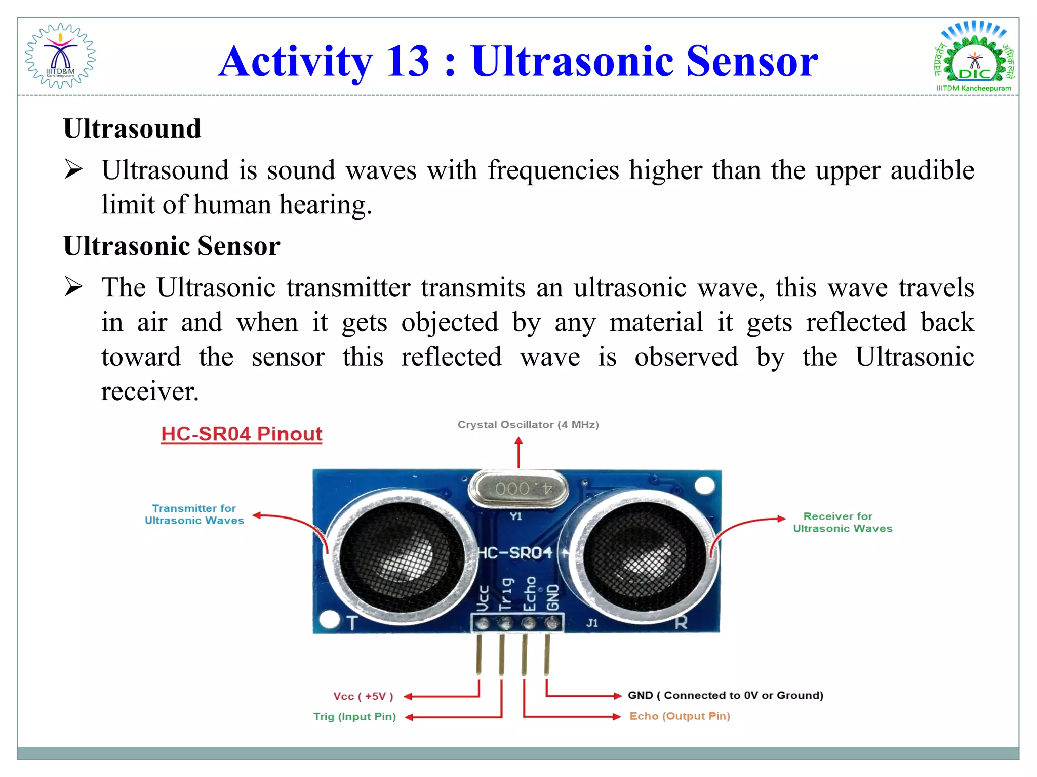
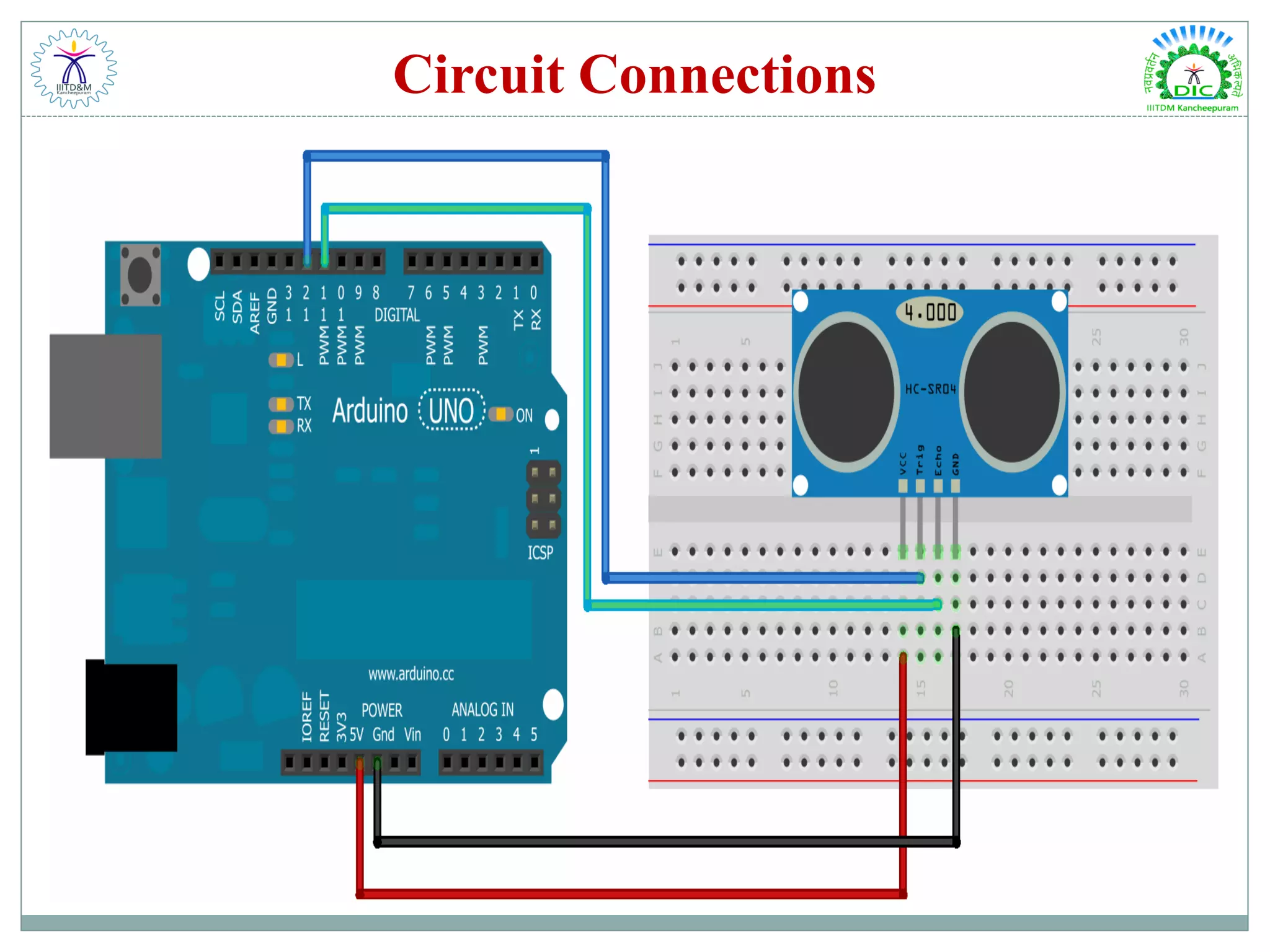
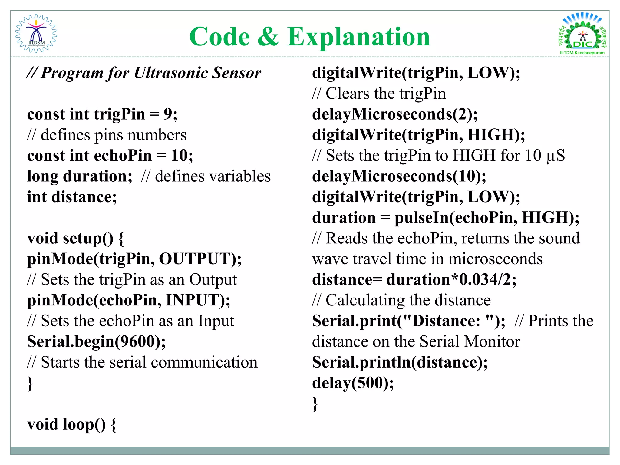
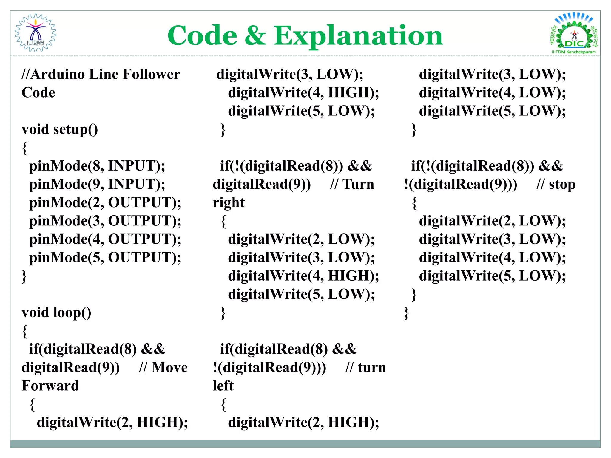
WORKSHOP ON ARDUINO DAY – 2: ADVANCE ARDUINO DESIGN INNOVATION CENTRE
Activity 9 : DC Motor Speed & Direction Control Motor: An electric motor is an electrical machine that converts electrical energy into mechanical energy. Most electric motors operate through the interaction between the motor's magnetic field and electric current in a wire winding to generate force in the form of rotation of a shaft. DC Motor The electric motor operated by direct current is called a DC Motor. This is a device that converts DC electrical energy into a mechanical energy.
DC Motor Driver What is Motor Driver?  A motor driver IC is an integrated circuit chip which is usually used to control motors in autonomous robots.  Motor driver ICs act as an interface between the microprocessor and the motors in a robot.  The most commonly used motor driver IC’s are from the L293 series such as L293D, L293NE, etc. Why Motor Driver?  Most microprocessors operate at low voltages and require a small amount of current to operate while the motors require a relatively higher voltages and current .  Thus current cannot be supplied to the motors from the microprocessor.  This is the primary need for the motor driver IC.
Circuit Connections
Code & Explanation /* Code for Dc Motor Speed & Direction Control */ #define button 8 #define pot 0 #define pwm1 9 #define pwm2 10 boolean motor_dir = 0; int motor_speed; void setup() { pinMode(pot, INPUT); pinMode(button, INPUT_PULLUP); pinMode(pwm1, OUTPUT); pinMode(pwm2, OUTPUT); Serial.begin(9600); } void loop() { motor_speed = analogRead(pot); Serial.println(pot); if(motor_dir) analogWrite(pwm1, motor_speed); else analogWrite(pwm2, motor_speed); if(!digitalRead(button)){ while(!digitalRead(button)); motor_dir = !motor_dir; if(motor_dir) digitalWrite(pwm2, 0); else digitalWrite(pwm1, 0); } }
Activity 10 : Servo Motor Servo Motor  A servomotor is a rotary actuator or linear actuator that allows for precise control of angular or linear position, velocity and acceleration.  It consists of a suitable motor coupled to a sensor for position feedback.  It also requires a relatively sophisticated controller, often a dedicated module designed specifically for use with servomotors.  Servo motor can be rotated from 0 to 180 degree.  Servo motors are rated in kg/cm (kilogram per centimeter) most servo motors are rated at 3kg/cm or 6kg/cm or 12kg/cm.  This kg/cm tells you how much weight your servo motor can lift at a particular distance. For example: A 6kg/cm Servo motor should be able to lift 6kg if load is suspended 1cm away from the motors shaft, the greater the distance the lesser the weight carrying capacity.
Circuit Connections
Code & Explanation /* Program to control Servo Motor*/ #include <Servo.h> Servo myservo; // create servo object to control a servo int pos = 0; // variable to store the servo position void setup() { myservo.attach(9); // attaches the servo on pin 9 to the servo object } void loop() { for (pos = 0; pos <= 180; pos += 1) { // goes from 0 degrees to 180 degrees in steps of 1 degree myservo.write(pos); // tell servo to go to position in variable 'pos' delay(15); // waits 15ms for the servo to reach the position } for (pos = 180; pos >= 0; pos -= 1) { // goes from 180 degrees to 0 degrees myservo.write(pos); // tell servo to go to position in variable 'pos' delay(15); // waits 15ms for the servo to reach the position } }
Activity 11 : DHT11 Temperature & Humidity Sensor Temperature & Humidity  The degree or intensity of heat present in a substance or object is its temperature.  Humidity is the concentration of water vapour present in air.  The temperature is measured with the help of a NTC thermistor or negative temperature coefficient thermistor.  These thermistors are usually made with semiconductors, ceramic and polymers.  The humidity is sensed using a moisture dependent resistor. It has two electrodes and in between them there exist a moisture holding substrate which holds moisture.  The conductance and hence resistance changes with changing humidity. PCB Size 22.0mm X 20.5mm X 1.6mm Working Voltage 3.3 or 5V DC Operating Voltage 3.3 or 5V DC Measure Range 20-95%RH;0-50℃ Resolution 8bit(temperature), 8bit(humidity)
Circuit Connections
Code & Explanation // Program for DHT11 #include "dht.h" #define dht_apin A0 // Pin sensor is connected to dht DHT; void setup(){ Serial.begin(9600); delay(500); //Delay to let system boot Serial.println("DHT11 Humidity & temperature Sensornn"); delay(1000); //Wait before accessing Sensor } //end void loop(){ //Start of Program DHT.read11(dht_apin); Serial.print("Current Humidity = "); Serial.print(DHT.humidity); Serial.print("% "); Serial.print("Temperature = "); Serial.print(DHT.temperature); Serial.println("C "); delay(2000); //Wait 2 seconds before accessing sensor again. //Fastest should be once every two seconds. } // end loop()
Activity 12 : Infrared Sensor Infrared (IR) Communication  Infrared (IR) is a wireless technology used for device communication over short ranges. IR transceivers are quite cheap and serve as short-range communication solution.  Infrared band of the electromagnet corresponds to 430THz to 300GHz and a wavelength of 980nm. IR Sensor Module  An IR sensor is a device which detects IR radiation falling on it. Applications: Night Vision, Surveillance, Thermography, Short – range communication, Astronomy, etc.
Circuit Connections
Code & Explanation // Program for IR Sensor to detect the obstacle and indicate on the serial monitor int LED = 13; // Use the onboard Uno LED int obstaclePin = 7; // This is our input pin int hasObstacle = HIGH; // High Means No Obstacle void setup() { pinMode(LED, OUTPUT); pinMode(obstaclePin, INPUT); Serial.begin(9600); } void loop() { hasObstacle = digitalRead(obstaclePin); //Reads the output of the obstacle sensor from the 7th PIN of the Digital section of the arduino if (hasObstacle == HIGH) { //High means something is ahead, so illuminates the 13th Port connected LED Serial.println("Stop something is ahead!!"); digitalWrite(LED, HIGH); //Illuminates the 13th Port LED } else{ Serial.println("Path is clear"); digitalWrite(LED, LOW); } delay(200); }
Activity 13 : Ultrasonic Sensor Ultrasound  Ultrasound is sound waves with frequencies higher than the upper audible limit of human hearing. Ultrasonic Sensor  The Ultrasonic transmitter transmits an ultrasonic wave, this wave travels in air and when it gets objected by any material it gets reflected back toward the sensor this reflected wave is observed by the Ultrasonic receiver.
Circuit Connections
Code & Explanation // Program for Ultrasonic Sensor const int trigPin = 9; // defines pins numbers const int echoPin = 10; long duration; // defines variables int distance; void setup() { pinMode(trigPin, OUTPUT); // Sets the trigPin as an Output pinMode(echoPin, INPUT); // Sets the echoPin as an Input Serial.begin(9600); // Starts the serial communication } void loop() { digitalWrite(trigPin, LOW); // Clears the trigPin delayMicroseconds(2); digitalWrite(trigPin, HIGH); // Sets the trigPin to HIGH for 10 µS delayMicroseconds(10); digitalWrite(trigPin, LOW); duration = pulseIn(echoPin, HIGH); // Reads the echoPin, returns the sound wave travel time in microseconds distance= duration*0.034/2; // Calculating the distance Serial.print("Distance: "); // Prints the distance on the Serial Monitor Serial.println(distance); delay(500); }
Ultrasonic Distance Calculation
Do It Yourself - Line Follower Line Follower  Line follower is an autonomous robot which follows either black line in white are or white line in black area. Robot must be able to detect particular line and keep following it. Concepts of Line Follower  Concept of working of line follower is related to light.  When light fall on a white surface it is almost fully reflected and in case of black surface, light is completely absorbed. This behaviour of light is used in building a line follower robot.
IR Sensor Principle
Block Diagram of Line Follower
Line Follower Working
Components
Line Follower Robot
Code & Explanation //Arduino Line Follower Code void setup() { pinMode(8, INPUT); pinMode(9, INPUT); pinMode(2, OUTPUT); pinMode(3, OUTPUT); pinMode(4, OUTPUT); pinMode(5, OUTPUT); } void loop() { if(digitalRead(8) && digitalRead(9)) // Move Forward { digitalWrite(2, HIGH); digitalWrite(3, LOW); digitalWrite(4, HIGH); digitalWrite(5, LOW); } if(!(digitalRead(8)) && digitalRead(9)) // Turn right { digitalWrite(2, LOW); digitalWrite(3, LOW); digitalWrite(4, HIGH); digitalWrite(5, LOW); } if(digitalRead(8) && !(digitalRead(9))) // turn left { digitalWrite(2, HIGH); digitalWrite(3, LOW); digitalWrite(4, LOW); digitalWrite(5, LOW); } if(!(digitalRead(8)) && !(digitalRead(9))) // stop { digitalWrite(2, LOW); digitalWrite(3, LOW); digitalWrite(4, LOW); digitalWrite(5, LOW); } }
Do It Yourself – Light Follower Light Follower A light follower robot is a light-seeking robot that moves toward areas of bright light. Light Dependent Resistor An LDR is a component that has a (variable) resistance that changes with the light intensity that falls upon it. This allows them to be used in light sensing circuits.
Code & Explanation //Light Follower Code void setup() { pinMode(A0,INPUT); //Right Sensor output to arduino input pinMode(2,OUTPUT); pinMode(3,OUTPUT); pinMode(4,OUTPUT); pinMode(5,OUTPUT); Serial.begin(9600); } void loop() { int sensor=analogRead(A0); delay(100); Serial.println(sensor); if (sensor >= 200){ digitalWrite(2,HIGH); digitalWrite(3,LOW); digitalWrite(4,HIGH); digitalWrite(5,LOW); } else{ digitalWrite(2,LOW); digitalWrite(3,LOW); digitalWrite(4,LOW); digitalWrite(5,LOW); } }
Do It Yourself – Obstacle Avoider Obstacle Avoider  This obstacle avoidance robot changes its path left or right depending on the point of obstacles in its way.  Here an Ultrasonic sensor is used to sense the obstacles in the path by calculating the distance between the robot and obstacle. If robot finds any obstacle it changes the direction and continue moving. Applications:  Mobile Robot Navigation Systems,  Automatic Vacuum Cleaning,  Unmanned Aerial Vehicles, etc.
Code & Explanation const int trigPin = 9; const int echoPin = 10; void setup() { pinMode(trigPin, OUTPUT); pinMode(echoPin, INPUT); pinMode (2, OUTPUT); pinMode (3, OUTPUT); pinMode (4, OUTPUT); pinMode (5, OUTPUT); Serial.begin(9600); } long duration, distance; void loop() { digitalWrite(trigPin, LOW); delayMicroseconds(3); digitalWrite(trigPin, HIGH); delayMicroseconds(12); digitalWrite(trigPin, LOW); duration = pulseIn(echoPin, HIGH); distance = duration/58.2; Serial.print(distance); Serial.println("CM"); delay(10); if(distance<20) { digitalWrite(2, LOW); digitalWrite(3, HIGH); digitalWrite(4, HIGH); digitalWrite(5, LOW); } else { digitalWrite(2, HIGH); digitalWrite(3, LOW); digitalWrite(4, HIGH); digitalWrite(5, LOW); } delay(90); }
Recommended Books
Additional Resources 1. https://www.arduino.cc/ - Arduino.cc is the home of Arduino platform. It has extensive learning materials such as Tutorials, References, code for using Arduino, Forum where you can post questions on issues/problems you have in your projects, etc. 2. http://makezine.com/ - Online page of Maker magazine, with lots of information on innovative technology projects including Arduino. 3. http://www.instructables.com/ - Lots of projects on technology and arts (including cooking), with step-by-instructions, photographs, and videos 4. http://appinventor.mit.edu/ - It allows the budding computer programmers to build their own apps that can be run on Android devices. It used a user-friendly graphical user-interface that allows drag-and-drop technique to build applications that impacts the world. 5. http://fritzing.org/ - Fritzing is open source computer aided design (CAD) software for electronic circuit design and printed circuit board (PCB) fabrication, especially with Arduino prototyping. It is an electronic design automation (EDA) tool for circuit designers.
Desgin Innovation Centre, Indian Institute of Information Technology, Design & Manufacturing, Kancheepuram, Chennai – 600127 E-mail: designinnovationcentre@gmail.com

Arduino Workshop Day 2 - Advance Arduino & DIY

  • 1.
    WORKSHOP ON ARDUINO DAY– 2: ADVANCE ARDUINO DESIGN INNOVATION CENTRE
  • 2.
    Activity 9 :DC Motor Speed & Direction Control Motor: An electric motor is an electrical machine that converts electrical energy into mechanical energy. Most electric motors operate through the interaction between the motor's magnetic field and electric current in a wire winding to generate force in the form of rotation of a shaft. DC Motor The electric motor operated by direct current is called a DC Motor. This is a device that converts DC electrical energy into a mechanical energy.
  • 3.
    DC Motor Driver Whatis Motor Driver?  A motor driver IC is an integrated circuit chip which is usually used to control motors in autonomous robots.  Motor driver ICs act as an interface between the microprocessor and the motors in a robot.  The most commonly used motor driver IC’s are from the L293 series such as L293D, L293NE, etc. Why Motor Driver?  Most microprocessors operate at low voltages and require a small amount of current to operate while the motors require a relatively higher voltages and current .  Thus current cannot be supplied to the motors from the microprocessor.  This is the primary need for the motor driver IC.
  • 4.
  • 5.
    Code & Explanation /*Code for Dc Motor Speed & Direction Control */ #define button 8 #define pot 0 #define pwm1 9 #define pwm2 10 boolean motor_dir = 0; int motor_speed; void setup() { pinMode(pot, INPUT); pinMode(button, INPUT_PULLUP); pinMode(pwm1, OUTPUT); pinMode(pwm2, OUTPUT); Serial.begin(9600); } void loop() { motor_speed = analogRead(pot); Serial.println(pot); if(motor_dir) analogWrite(pwm1, motor_speed); else analogWrite(pwm2, motor_speed); if(!digitalRead(button)){ while(!digitalRead(button)); motor_dir = !motor_dir; if(motor_dir) digitalWrite(pwm2, 0); else digitalWrite(pwm1, 0); } }
  • 6.
    Activity 10 :Servo Motor Servo Motor  A servomotor is a rotary actuator or linear actuator that allows for precise control of angular or linear position, velocity and acceleration.  It consists of a suitable motor coupled to a sensor for position feedback.  It also requires a relatively sophisticated controller, often a dedicated module designed specifically for use with servomotors.  Servo motor can be rotated from 0 to 180 degree.  Servo motors are rated in kg/cm (kilogram per centimeter) most servo motors are rated at 3kg/cm or 6kg/cm or 12kg/cm.  This kg/cm tells you how much weight your servo motor can lift at a particular distance. For example: A 6kg/cm Servo motor should be able to lift 6kg if load is suspended 1cm away from the motors shaft, the greater the distance the lesser the weight carrying capacity.
  • 7.
  • 8.
    Code & Explanation /*Program to control Servo Motor*/ #include <Servo.h> Servo myservo; // create servo object to control a servo int pos = 0; // variable to store the servo position void setup() { myservo.attach(9); // attaches the servo on pin 9 to the servo object } void loop() { for (pos = 0; pos <= 180; pos += 1) { // goes from 0 degrees to 180 degrees in steps of 1 degree myservo.write(pos); // tell servo to go to position in variable 'pos' delay(15); // waits 15ms for the servo to reach the position } for (pos = 180; pos >= 0; pos -= 1) { // goes from 180 degrees to 0 degrees myservo.write(pos); // tell servo to go to position in variable 'pos' delay(15); // waits 15ms for the servo to reach the position } }
  • 9.
    Activity 11 :DHT11 Temperature & Humidity Sensor Temperature & Humidity  The degree or intensity of heat present in a substance or object is its temperature.  Humidity is the concentration of water vapour present in air.  The temperature is measured with the help of a NTC thermistor or negative temperature coefficient thermistor.  These thermistors are usually made with semiconductors, ceramic and polymers.  The humidity is sensed using a moisture dependent resistor. It has two electrodes and in between them there exist a moisture holding substrate which holds moisture.  The conductance and hence resistance changes with changing humidity. PCB Size 22.0mm X 20.5mm X 1.6mm Working Voltage 3.3 or 5V DC Operating Voltage 3.3 or 5V DC Measure Range 20-95%RH;0-50℃ Resolution 8bit(temperature), 8bit(humidity)
  • 10.
  • 11.
    Code & Explanation //Program for DHT11 #include "dht.h" #define dht_apin A0 // Pin sensor is connected to dht DHT; void setup(){ Serial.begin(9600); delay(500); //Delay to let system boot Serial.println("DHT11 Humidity & temperature Sensornn"); delay(1000); //Wait before accessing Sensor } //end void loop(){ //Start of Program DHT.read11(dht_apin); Serial.print("Current Humidity = "); Serial.print(DHT.humidity); Serial.print("% "); Serial.print("Temperature = "); Serial.print(DHT.temperature); Serial.println("C "); delay(2000); //Wait 2 seconds before accessing sensor again. //Fastest should be once every two seconds. } // end loop()
  • 12.
    Activity 12 :Infrared Sensor Infrared (IR) Communication  Infrared (IR) is a wireless technology used for device communication over short ranges. IR transceivers are quite cheap and serve as short-range communication solution.  Infrared band of the electromagnet corresponds to 430THz to 300GHz and a wavelength of 980nm. IR Sensor Module  An IR sensor is a device which detects IR radiation falling on it. Applications: Night Vision, Surveillance, Thermography, Short – range communication, Astronomy, etc.
  • 13.
  • 14.
    Code & Explanation //Program for IR Sensor to detect the obstacle and indicate on the serial monitor int LED = 13; // Use the onboard Uno LED int obstaclePin = 7; // This is our input pin int hasObstacle = HIGH; // High Means No Obstacle void setup() { pinMode(LED, OUTPUT); pinMode(obstaclePin, INPUT); Serial.begin(9600); } void loop() { hasObstacle = digitalRead(obstaclePin); //Reads the output of the obstacle sensor from the 7th PIN of the Digital section of the arduino if (hasObstacle == HIGH) { //High means something is ahead, so illuminates the 13th Port connected LED Serial.println("Stop something is ahead!!"); digitalWrite(LED, HIGH); //Illuminates the 13th Port LED } else{ Serial.println("Path is clear"); digitalWrite(LED, LOW); } delay(200); }
  • 15.
    Activity 13 :Ultrasonic Sensor Ultrasound  Ultrasound is sound waves with frequencies higher than the upper audible limit of human hearing. Ultrasonic Sensor  The Ultrasonic transmitter transmits an ultrasonic wave, this wave travels in air and when it gets objected by any material it gets reflected back toward the sensor this reflected wave is observed by the Ultrasonic receiver.
  • 16.
  • 17.
    Code & Explanation //Program for Ultrasonic Sensor const int trigPin = 9; // defines pins numbers const int echoPin = 10; long duration; // defines variables int distance; void setup() { pinMode(trigPin, OUTPUT); // Sets the trigPin as an Output pinMode(echoPin, INPUT); // Sets the echoPin as an Input Serial.begin(9600); // Starts the serial communication } void loop() { digitalWrite(trigPin, LOW); // Clears the trigPin delayMicroseconds(2); digitalWrite(trigPin, HIGH); // Sets the trigPin to HIGH for 10 µS delayMicroseconds(10); digitalWrite(trigPin, LOW); duration = pulseIn(echoPin, HIGH); // Reads the echoPin, returns the sound wave travel time in microseconds distance= duration*0.034/2; // Calculating the distance Serial.print("Distance: "); // Prints the distance on the Serial Monitor Serial.println(distance); delay(500); }
  • 18.
  • 19.
    Do It Yourself- Line Follower Line Follower  Line follower is an autonomous robot which follows either black line in white are or white line in black area. Robot must be able to detect particular line and keep following it. Concepts of Line Follower  Concept of working of line follower is related to light.  When light fall on a white surface it is almost fully reflected and in case of black surface, light is completely absorbed. This behaviour of light is used in building a line follower robot.
  • 20.
  • 21.
    Block Diagram ofLine Follower
  • 22.
  • 23.
  • 24.
  • 25.
    Code & Explanation //ArduinoLine Follower Code void setup() { pinMode(8, INPUT); pinMode(9, INPUT); pinMode(2, OUTPUT); pinMode(3, OUTPUT); pinMode(4, OUTPUT); pinMode(5, OUTPUT); } void loop() { if(digitalRead(8) && digitalRead(9)) // Move Forward { digitalWrite(2, HIGH); digitalWrite(3, LOW); digitalWrite(4, HIGH); digitalWrite(5, LOW); } if(!(digitalRead(8)) && digitalRead(9)) // Turn right { digitalWrite(2, LOW); digitalWrite(3, LOW); digitalWrite(4, HIGH); digitalWrite(5, LOW); } if(digitalRead(8) && !(digitalRead(9))) // turn left { digitalWrite(2, HIGH); digitalWrite(3, LOW); digitalWrite(4, LOW); digitalWrite(5, LOW); } if(!(digitalRead(8)) && !(digitalRead(9))) // stop { digitalWrite(2, LOW); digitalWrite(3, LOW); digitalWrite(4, LOW); digitalWrite(5, LOW); } }
  • 26.
    Do It Yourself– Light Follower Light Follower A light follower robot is a light-seeking robot that moves toward areas of bright light. Light Dependent Resistor An LDR is a component that has a (variable) resistance that changes with the light intensity that falls upon it. This allows them to be used in light sensing circuits.
  • 27.
    Code & Explanation //LightFollower Code void setup() { pinMode(A0,INPUT); //Right Sensor output to arduino input pinMode(2,OUTPUT); pinMode(3,OUTPUT); pinMode(4,OUTPUT); pinMode(5,OUTPUT); Serial.begin(9600); } void loop() { int sensor=analogRead(A0); delay(100); Serial.println(sensor); if (sensor >= 200){ digitalWrite(2,HIGH); digitalWrite(3,LOW); digitalWrite(4,HIGH); digitalWrite(5,LOW); } else{ digitalWrite(2,LOW); digitalWrite(3,LOW); digitalWrite(4,LOW); digitalWrite(5,LOW); } }
  • 28.
    Do It Yourself– Obstacle Avoider Obstacle Avoider  This obstacle avoidance robot changes its path left or right depending on the point of obstacles in its way.  Here an Ultrasonic sensor is used to sense the obstacles in the path by calculating the distance between the robot and obstacle. If robot finds any obstacle it changes the direction and continue moving. Applications:  Mobile Robot Navigation Systems,  Automatic Vacuum Cleaning,  Unmanned Aerial Vehicles, etc.
  • 29.
    Code & Explanation constint trigPin = 9; const int echoPin = 10; void setup() { pinMode(trigPin, OUTPUT); pinMode(echoPin, INPUT); pinMode (2, OUTPUT); pinMode (3, OUTPUT); pinMode (4, OUTPUT); pinMode (5, OUTPUT); Serial.begin(9600); } long duration, distance; void loop() { digitalWrite(trigPin, LOW); delayMicroseconds(3); digitalWrite(trigPin, HIGH); delayMicroseconds(12); digitalWrite(trigPin, LOW); duration = pulseIn(echoPin, HIGH); distance = duration/58.2; Serial.print(distance); Serial.println("CM"); delay(10); if(distance<20) { digitalWrite(2, LOW); digitalWrite(3, HIGH); digitalWrite(4, HIGH); digitalWrite(5, LOW); } else { digitalWrite(2, HIGH); digitalWrite(3, LOW); digitalWrite(4, HIGH); digitalWrite(5, LOW); } delay(90); }
  • 30.
  • 31.
    Additional Resources 1. https://www.arduino.cc/- Arduino.cc is the home of Arduino platform. It has extensive learning materials such as Tutorials, References, code for using Arduino, Forum where you can post questions on issues/problems you have in your projects, etc. 2. http://makezine.com/ - Online page of Maker magazine, with lots of information on innovative technology projects including Arduino. 3. http://www.instructables.com/ - Lots of projects on technology and arts (including cooking), with step-by-instructions, photographs, and videos 4. http://appinventor.mit.edu/ - It allows the budding computer programmers to build their own apps that can be run on Android devices. It used a user-friendly graphical user-interface that allows drag-and-drop technique to build applications that impacts the world. 5. http://fritzing.org/ - Fritzing is open source computer aided design (CAD) software for electronic circuit design and printed circuit board (PCB) fabrication, especially with Arduino prototyping. It is an electronic design automation (EDA) tool for circuit designers.
  • 32.
    Desgin Innovation Centre, IndianInstitute of Information Technology, Design & Manufacturing, Kancheepuram, Chennai – 600127 E-mail: designinnovationcentre@gmail.com