Coherent and Non-coherent detection of ASK, FSK AND QASK
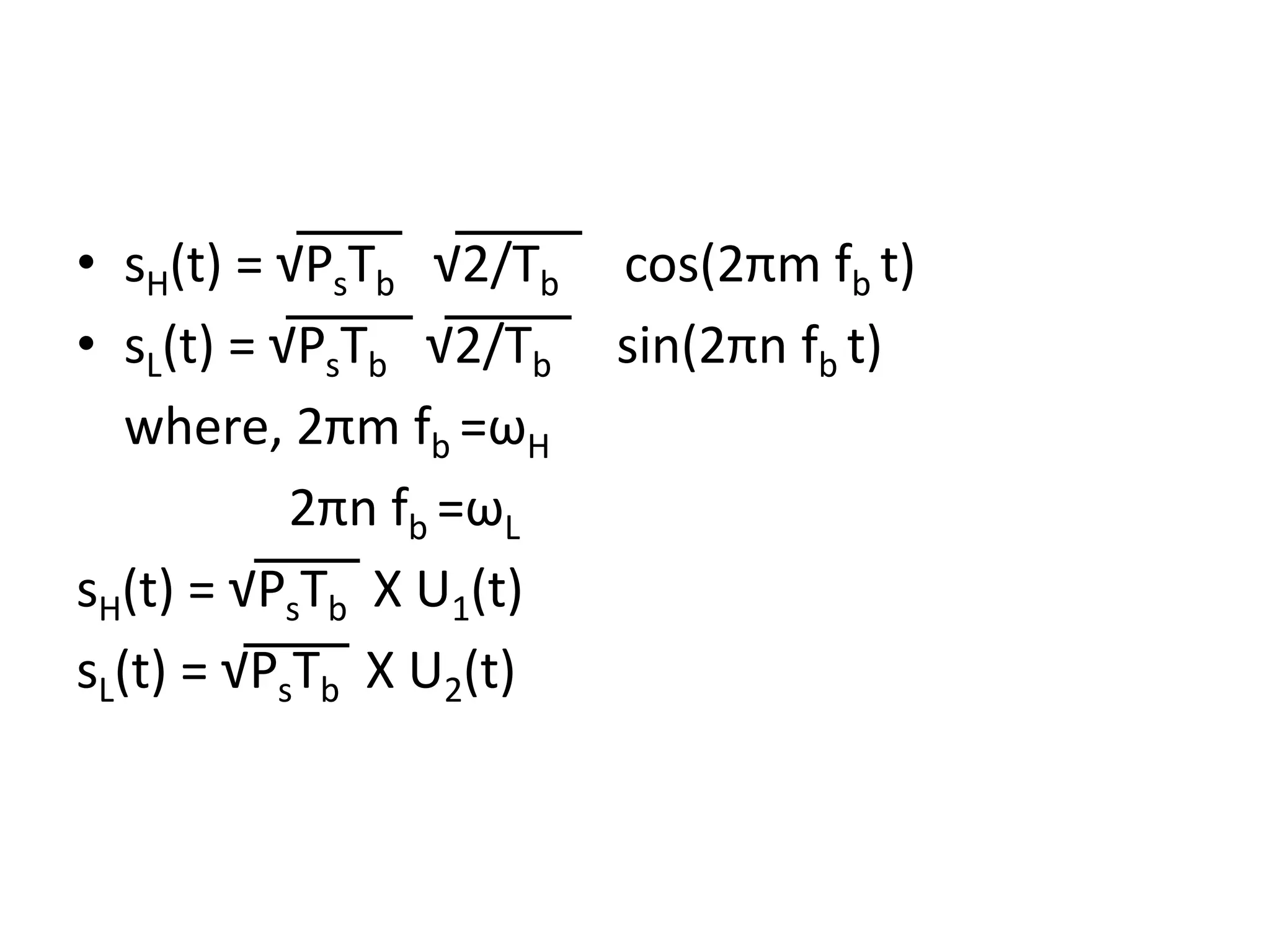
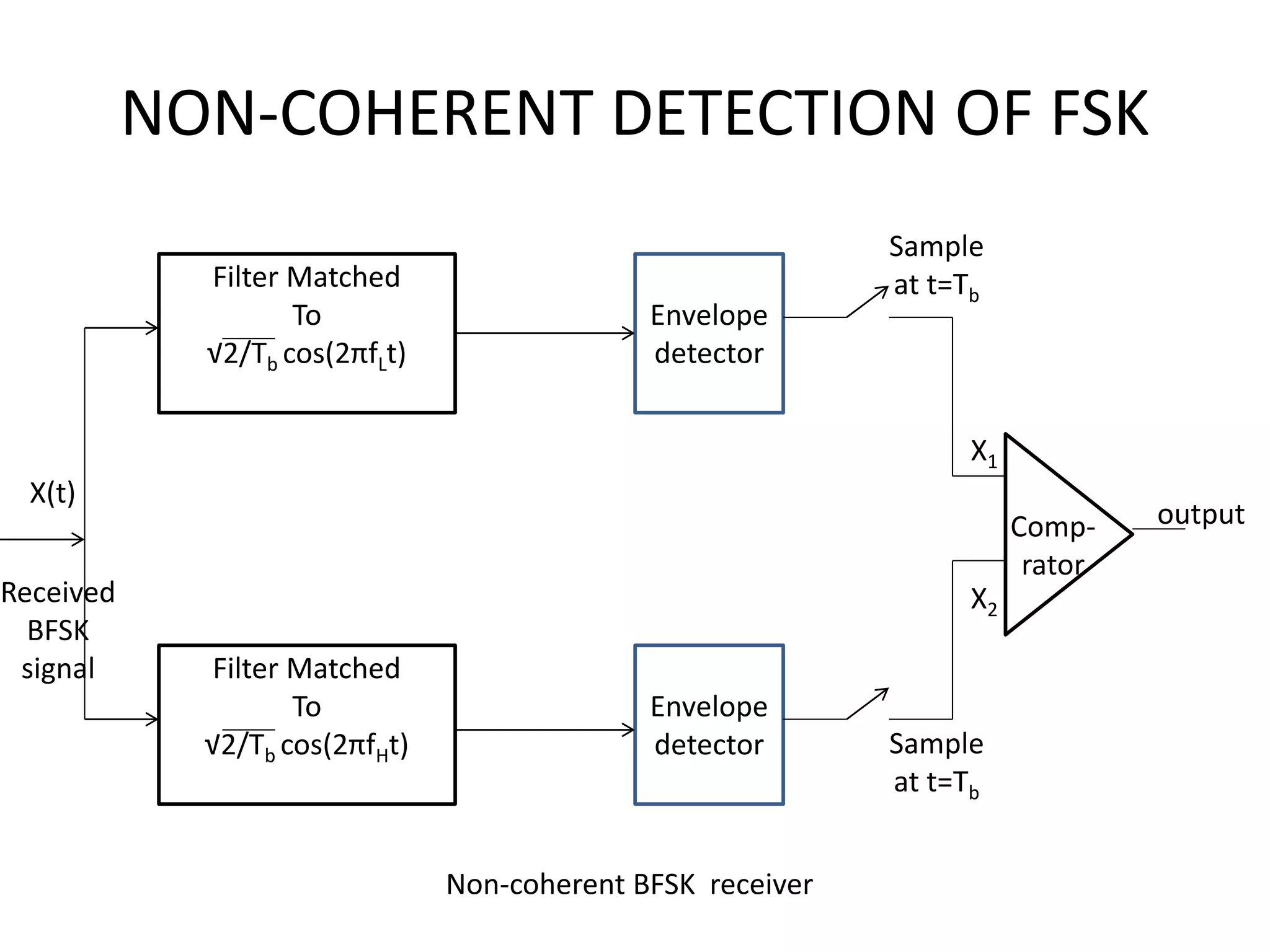
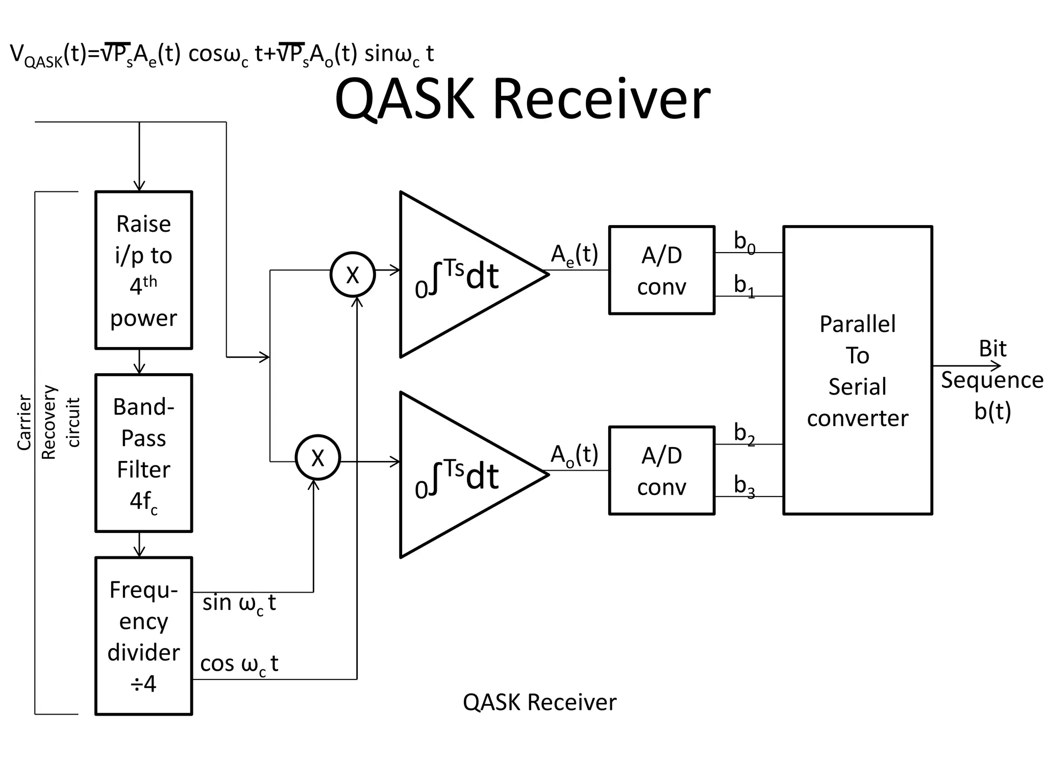
This document discusses different digital communication techniques including coherent and non-coherent detection methods for amplitude shift keying (ASK), frequency shift keying (FSK) and quadrature amplitude shift keying (QASK). Coherent detection requires a reference carrier wave and exploits phase information, while non-coherent detection does not require a reference wave. It then describes the receiver designs for coherent and non-coherent detection of ASK and FSK. For QASK, it outlines raising the input signal to the fourth power before bandpass filtering and frequency division to recover the transmitted bit sequence.
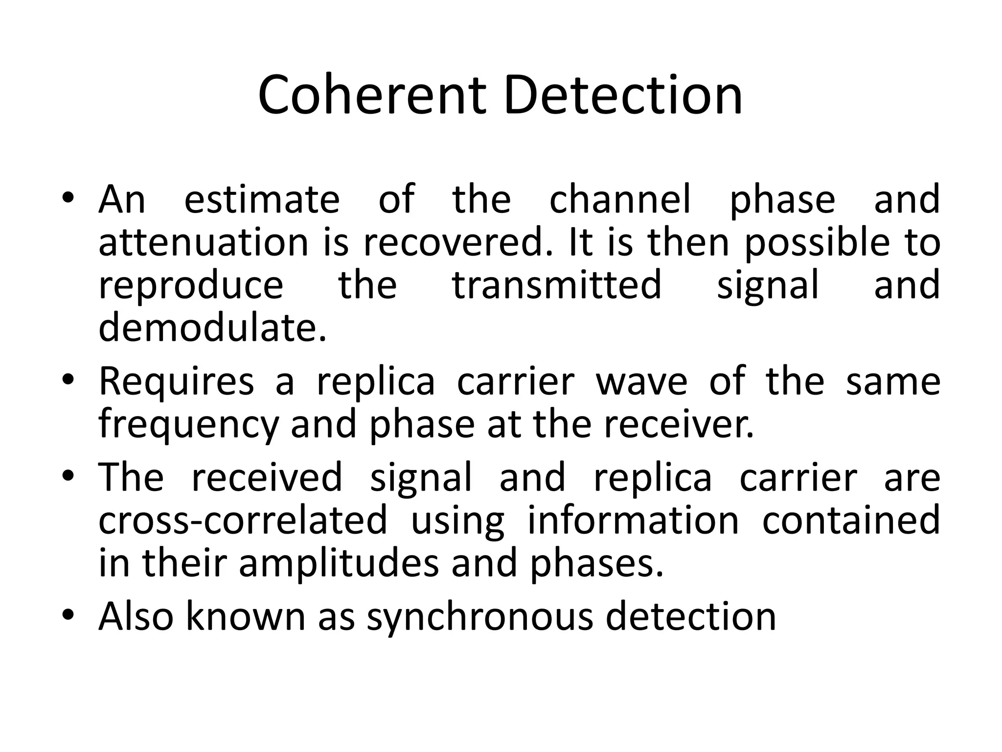
Coherent Detection • Anestimate of the channel phase and attenuation is recovered. It is then possible to reproduce the transmitted signal and demodulate. • Requires a replica carrier wave of the same frequency and phase at the receiver. • The received signal and replica carrier are cross-correlated using information contained in their amplitudes and phases. • Also known as synchronous detection
4.
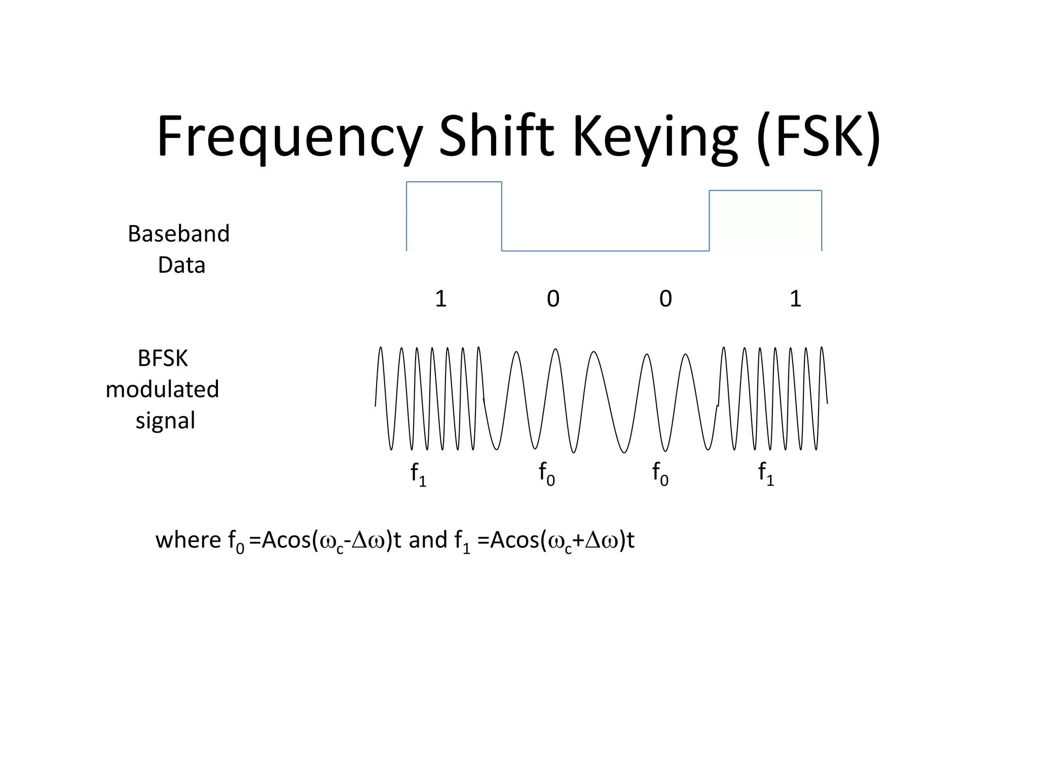
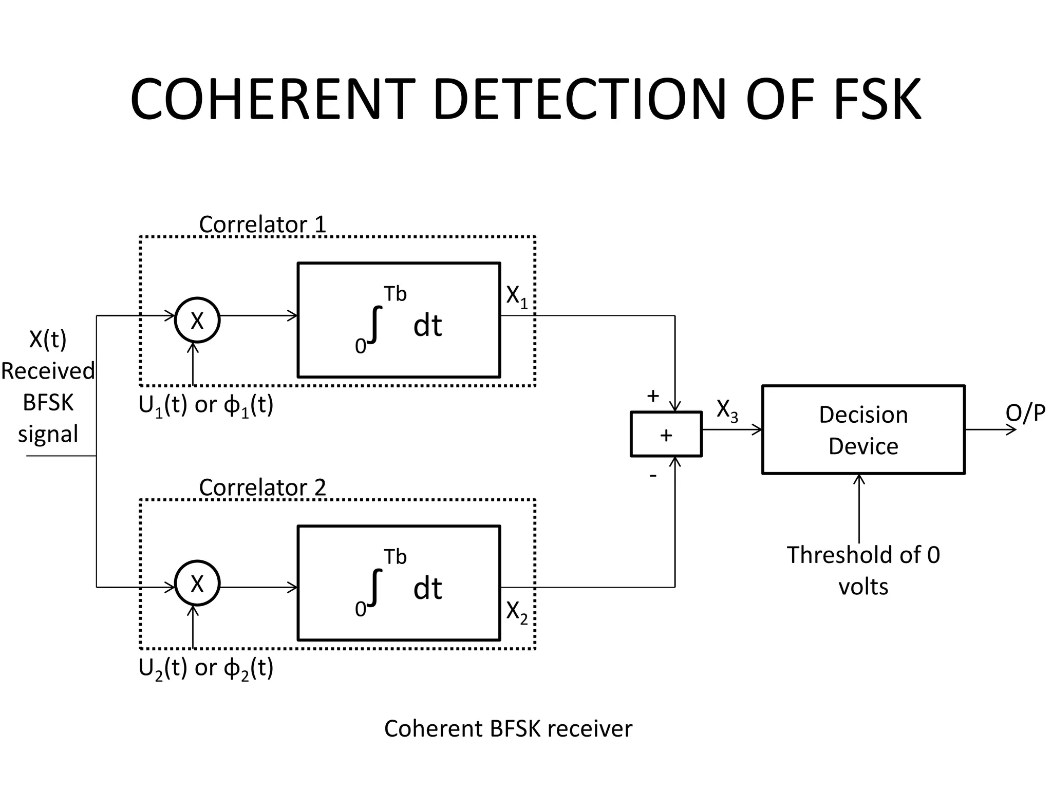
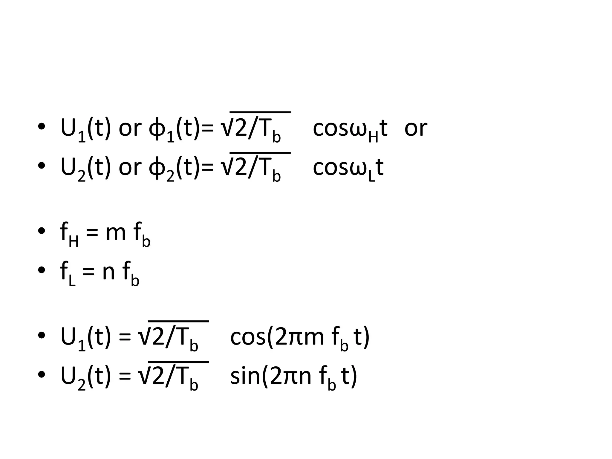
• Applicable to –Phase Shift Keying (PSK) – Frequency Shift Keying (FSK) – Amplitude Shift Keying (ASK)
5.
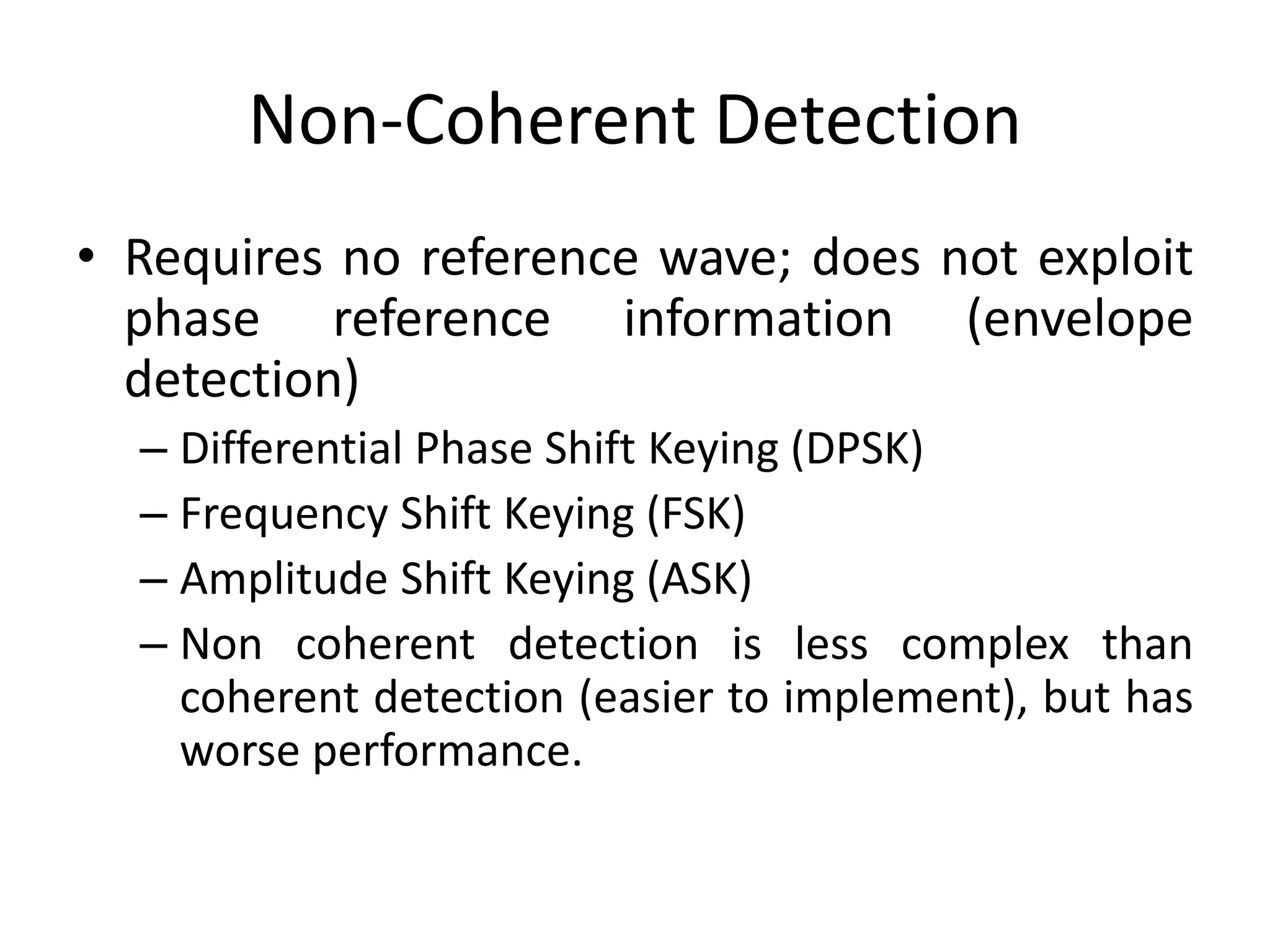
Non-Coherent Detection • Requiresno reference wave; does not exploit phase reference information (envelope detection) – Differential Phase Shift Keying (DPSK) – Frequency Shift Keying (FSK) – Amplitude Shift Keying (ASK) – Non coherent detection is less complex than coherent detection (easier to implement), but has worse performance.
6.
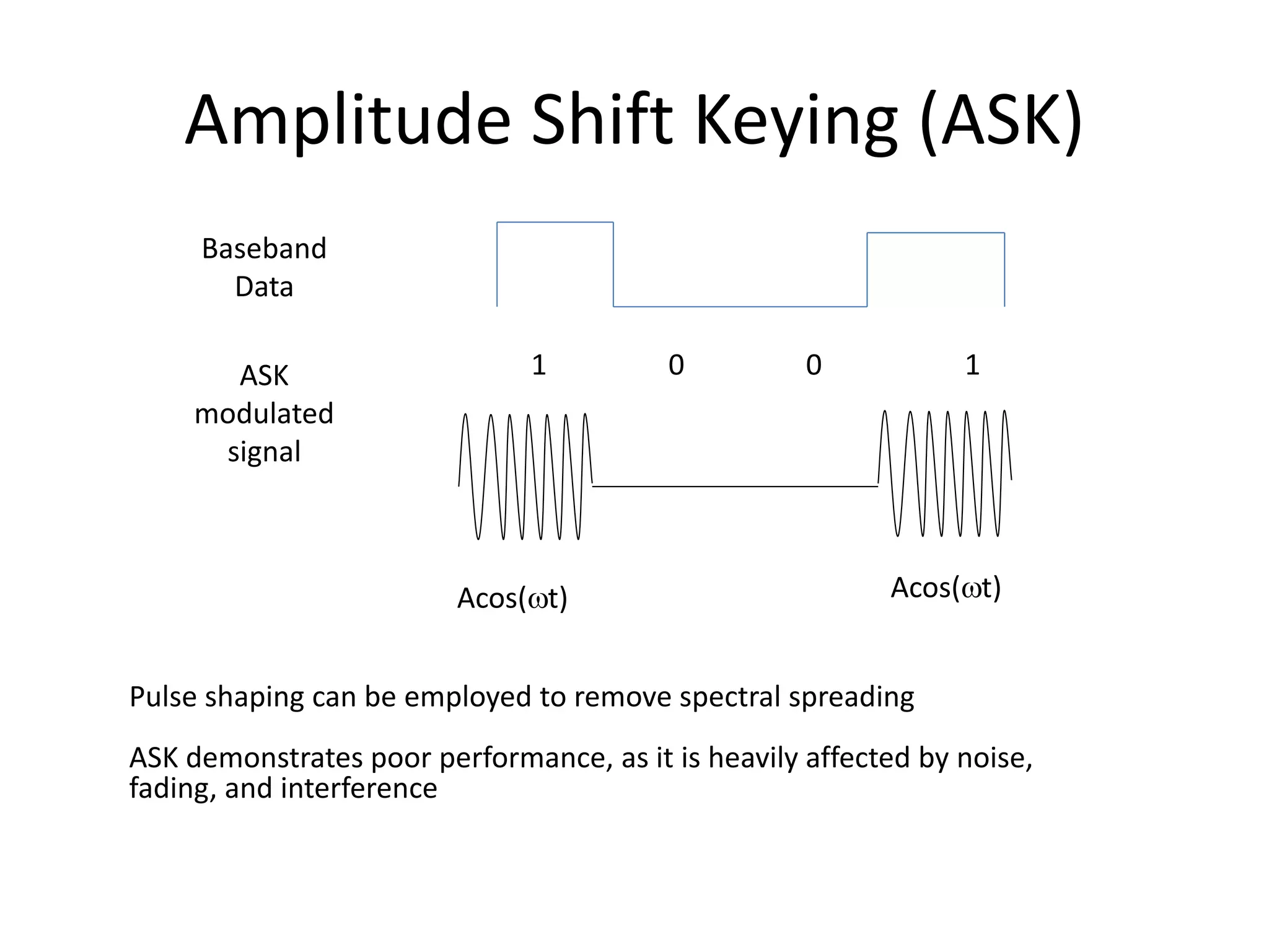
Amplitude Shift Keying(ASK) Baseband Data ASK modulated signal 1 10 0 Acos(t) Acos(t) Pulse shaping can be employed to remove spectral spreading ASK demonstrates poor performance, as it is heavily affected by noise, fading, and interference
7.
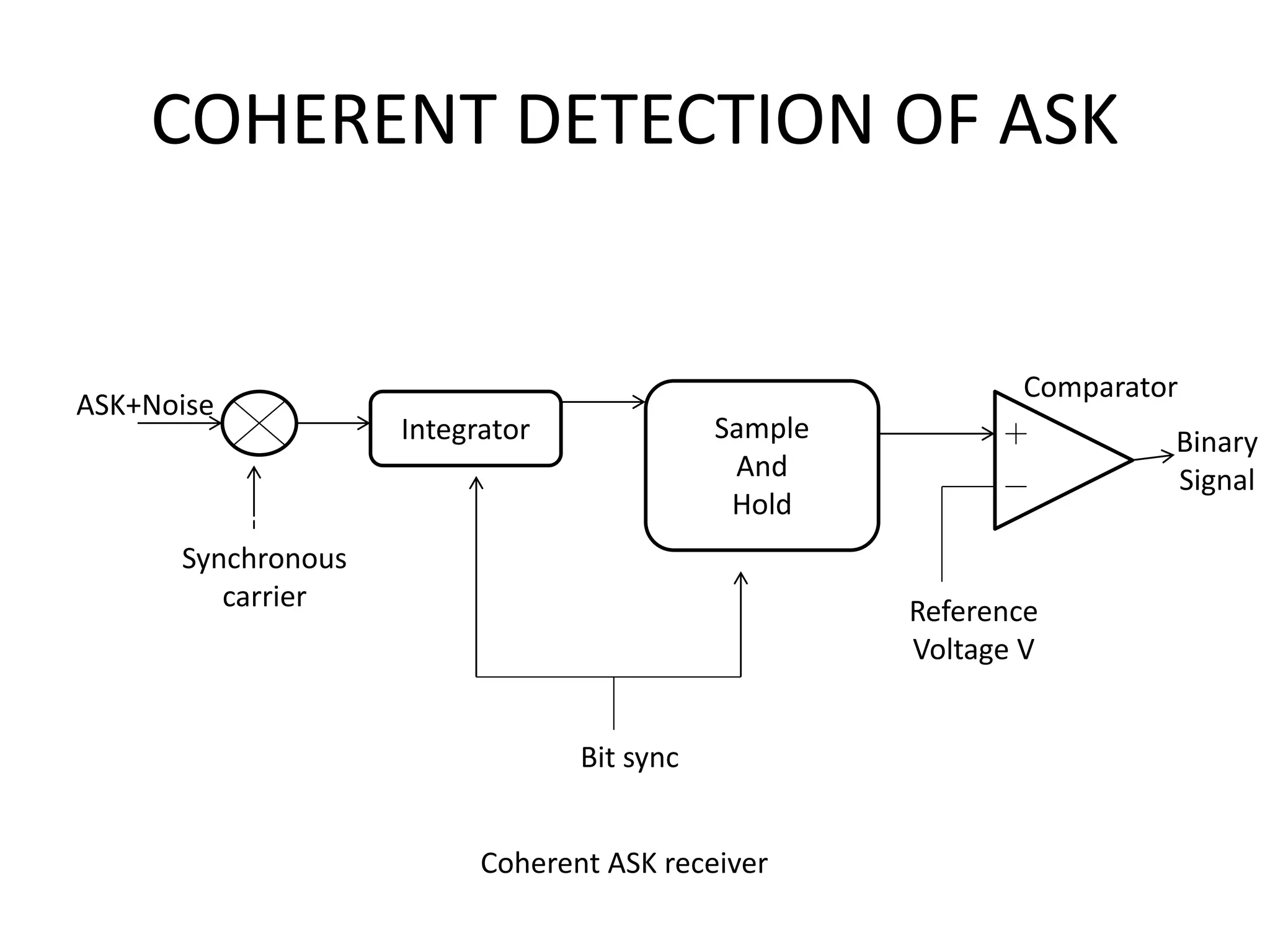
COHERENT DETECTION OFASK ASK+Noise Integrator Sample And Hold Synchronous carrier Comparator Binary Signal Reference Voltage V Bit sync Coherent ASK receiver
8.
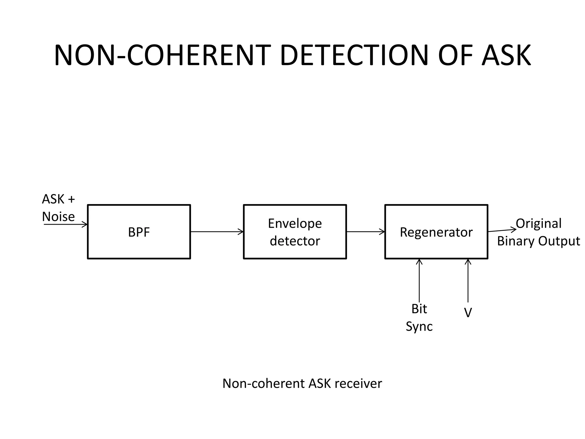
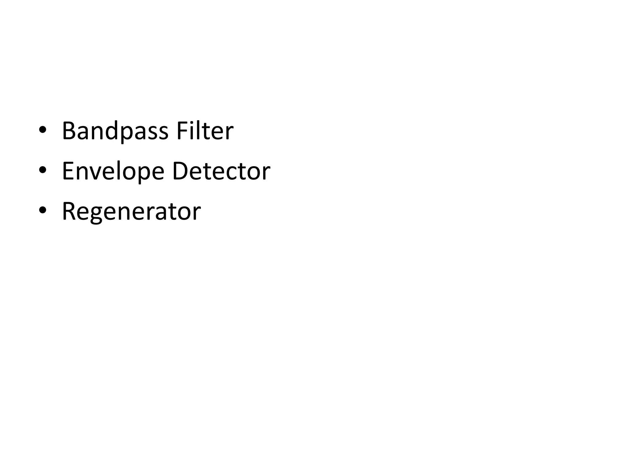
NON-COHERENT DETECTION OFASK BPF Envelope detector Regenerator ASK + Noise Original Binary Output Bit Sync V Non-coherent ASK receiver