Download to read offline
![International Research Journal of Engineering and Technology (IRJET) e-ISSN: 2395-0056 Volume: 10 Issue: 07 | July 2023 www.irjet.net p-ISSN: 2395-0072 © 2023, IRJET | Impact Factor value: 8.226 | ISO 9001:2008 Certified Journal | Page 241 Face Recognition Based on Image Processing in an Advanced Robotic System Amandeep Kaur1, Swati Sharma1, Sumit Asthana1 , Sushil Kumar Pal 1, Anshuman Singh 1, Vishal Kumar 1, Vivek Kumar1 1Department of Instrumentation, Bhaskaracharya College of Applied Sciences, University of Delhi ---------------------------------------------------------------------***--------------------------------------------------------------------- Abstract - In the present work, face recognition system has been developed using image processing technique. Thesystem developed works in two stages. In the first stage, face recognition algorithm is used to unlock the system by a valid user face. Once the system is unlocked, then the motion of robot is controlled using different navigation images. Face recognization is implemented using SVM (support vector machine), HOG (histogram of oriented gradients)and kNN(k- nearest neighbors) algorithm inMATLAB. Thewholeprocessis based on the concept called Machine Learning in artificial intelligence. Here we are dealing with supervised machine learning technique where the machine is trained insupervised manner. Key Words: Face recognition, SVM, HOG, KNN, Machine learning 1. INTRODUCTION The field of digital image processing has grown rapidly after 1960, after the development of hi-speed computer. It has found importance in mainly two areas: (i) Improvement of pictorial information for better human interpretation and the second being the processing of a scene data for an autonomous machine perception. The first feature i.e.image enhancement and restoration are used to process degraded or blurred images. As per medical imaging is concerned, most of the images may be used in the detectionoftumorsor for screening the patients. Whereas second feature i.e. machine perception can be employedinautomatic character recognition, industrial machine vision for product assembly and inspection. The continuing decline in the ratio of computer price to performance and the expansion of networking and communication bandwidth via the world wide web and the Internet have created unprecedented opportunities for continued growth of digital image processing [1]. Digital image processing basically includes the following three steps: Importing the image with optical scanner, analyzing and manipulating the image and Output is the last stage in which result can be altered image or report that is based on image analysis. It can be used to perform various tasks such as: (i) Visualization of the objects that are not visible, (ii) Image sharpening and restoration to create a better image, (iii) Image retrieval to seek image of interest, (iv) Measurement of pattern in an image and (v) Image Recognition – Distinguish the objects in an image [2]. In the present work, we will be implementing the(v)part i.e. Face recognition. As we know that face plays a major role in our social intercourse in conveyingidentityandexpressions. The human ability to recognize faces is remarkable. We can recognize thousandsoffaces learnedthroughoutourlifetime and identify familiar faces at a glance even after years of separation. But developing a computational model of face recognition is quite difficult, because faces are complex, multidimensional, and subject to change over time and integration of face recognition in robotics is more difficult [3-4]. Face recognition has its applications in various fields. Machines and technology are increasing rapidly, butwelack a system which can distinguish between different users and respond to that uniquely. Today most of the systems are blind because they cannot differentiate between valid and invalid users. Keeping security breaching in mind, face recognition based system must be developed in order to improve security level. Facerecognition isa partofadvanced image processing which can be achieved using image processing algorithm as shown in Figure 1[5]. Fig 1- Image Processing Flow chart](https://image.slidesharecdn.com/irjet-v10i735-230815104341-79c54dee/75/Face-Recognition-Based-on-Image-Processing-in-an-Advanced-Robotic-System-1-2048.jpg)
![International Research Journal of Engineering and Technology (IRJET) e-ISSN: 2395-0056 Volume: 10 Issue: 07 | July 2023 www.irjet.net p-ISSN: 2395-0072 © 2023, IRJET | Impact Factor value: 8.226 | ISO 9001:2008 Certified Journal | Page 242 In the past few years, various researchers have done work on face recognition algorithm. Most of them have workedon Principal component analysis (PCA) algorithm in MATLAB. This approach reduces the dimension of the data/image by means of data compression which might cause loss in the information. It also reduces the dimensions of the data. Also PCA uses 1D array to store the information of the test data, which leads to insufficiency of space for data storage. Apart from this, some other workers have used Back Propagation Neural Network (BPNN) algorithm for classification of training data and run time captured test data/image, which is a very complex process of neural network of artificial intelligence [7]. Both these methods are complex and produces unsatisfactory results. In the present work,facerecognizationisimplementedusing SVM (support vector machine), HOG (histogram of oriented gradients) and kNN (k-nearest neighbors) algorithm in MATLAB. Further, we have usedthismodel incontrolling the motion of the robot. 2. Working Model Working model of a face recognition based system can be majorly described in two stages. Both the stages uses image processing. In the first stage, Face recognition algorithm is used to unlock the system by a valid user face. Valid face images will be pre-stored in the system. Once the system is unlocked, then the motion of robot is controlled using different navigation images. The whole process is based on the conceptcalled MachineLearning in artificial intelligence. Here we are dealing with supervised machine learning technique where the machine is trained in supervised manner. We have used various algorithm of MATLAB to acheieve this. We will now discuss them one by one. HOG is a function used in MATLAB, which finds the gradients of each pixel of an image captured during run time.Gradients obtained are used to build a histogram of gradients and then they are stored in a 2D array, which is then assigned with a group name and it can be further used for classification of an image. While using HOG, there are no problem of data compression and dimensions reductions, so there is no chance of loss of information. In addition to this, HOG descriptor has advantages over other descriptors, as it is invariant to geometric and photometric transformations.[8] Image captured is displayed on a window using command ‘imshow(imr)’ and HOGfeatureofrealtimecapturedimageis then extracted usingcommand‘extractHOGFeatures’.Finally using command ‘[feat] = hog_feature_vector(imr)’ the extracted HOG feature is represented in the form of a vector, i.e. vectorisation is done. Here, pause is required for the captured images to appear on window clearly. Fig 2- HOG function working Before proceeding further, let’s understand the working of HOG function. As shown in Figure2, [9] the imagecapturedis divided into cells and then orientation of gradients is being found foreach cell. After gradient orientation has beenfound successfully, it’s been concatenated to form a histogram and finally histogram is shown in vector form. Support Vector Machine (SVM)- While dealing with complex data sets such as faces, kNN cannot be used. KNN is a classifier which deals with data sets that are easy to handle and operate whereas SVM classifier deals with data sets that are closely related to eachotherinthematterofresemblance. As we know, human faces are similar to each other to a high extent, so face recognition needs to have a classifier which can be able to differentiate between such similar data sets. It uses the concept of hyperplane for classification. It creates a line or a hyper-plane between two sets of data which are related to each other at alarge extent and thusseparatethem out precisely. We are using SVM here in a way to classify the real time image captured with the images of human faces already present in the system. SVM takes two data sets at random and separate them out using a hyperplane. Hyperplane can be treated here as a boundary between data sets. Now these two data sets are matched with the real time captured image data set using a classifierandthusitgivesthe optimum result. SVM is used here to match the feature of an image with the training data set so that system can authenticate a user and unlock it, if it finds an authentic face. In machine learning, SVMs are supervised learning models with associated learning algorithms that analyze data used for classification. [10] SVM function is used as a classifier for face recognition operation. Our main task here is to find the optimal matches of the human face images captured during run time. The command ‘SVM_Mdl = fitcecoc(fea,group)’ is used to find the match of the feature group and then command ‘c = predict(SVM_Mdl,test_feature)’ is used for prediction of test feature group which is closely related to the run time captured images features.](https://image.slidesharecdn.com/irjet-v10i735-230815104341-79c54dee/75/Face-Recognition-Based-on-Image-Processing-in-an-Advanced-Robotic-System-2-2048.jpg)
![International Research Journal of Engineering and Technology (IRJET) e-ISSN: 2395-0056 Volume: 10 Issue: 07 | July 2023 www.irjet.net p-ISSN: 2395-0072 © 2023, IRJET | Impact Factor value: 8.226 | ISO 9001:2008 Certified Journal | Page 245 they are used to move the robot in forward direction. We can see in the window on the right sideof the figurebelow,arrow image is being processed and converted into gray scale and then its feature is extracted. The similar results are obtained for ‘BACKWARD’, ‘LEFTWARD’, ‘RIGHTWARD’ directions. Fig 8- Controlling Robotic Motion with the help of arrow image 3. CONCLUSIONS The face recognition system for advanceduseinroboticshas been successfully developed which performs the desired functions satisfactorily. As projected, the system efficiently unlocks for the defined user and enables him to access the robot. The robot in turn, also performs the desired movements adequately as instructed by the user. Multiple users can be defined for giving the access by incorporating their details in the program. Users can be added, deleted or changed as per our application by modifyingtheprogram. In future, we propose to introduce a high end security system called IRIS scanner and identifier. It can be implemented in our robotic system to first scan and identify an authentic user’s iris and then use this information for high level robotics operation. REFERENCES [1] Digital image processing 3rd edition, Rafael C. Gonzalez [2] Yan Sun,1Zhenyun Ren,1and Wenxi Zheng, Research on Face Recognition Algorithm Based on Image Processing, Computational Intelligence and Neuroscience Volume 2022 [3] M.A. Turk and A.P. Pentland. “Facerecognitionusing Eigenfaces”. In Proc.ofComputerVisionand Pattern Recognition, pages 586-591.IEEE, June 1991b. [4] Facial Recognition Using Image Processing Dr. Madhusudhan, Chinmaya Dayananda Kamath, Darshan Naik M , Chinmaya Bhatt K, Shreyas, International Journal of Advanced Research in Science, Communication and Technology(IJARSCT) Volume 2, Issue 2, March 2022 . [5] A MATLAB based Face Recognition System using Image Processing and Neural NetworksJawadNagi, Syed Khaleel Ahmed FarrukhNagi4thInternational Colloquium on Signal Processing and its Applications, March 7-9, 2008, Kuala Lumpur, Malaysia. [6] Roza Dastres and Mohsen Soori , Advanced Image processing systems, Internationational journal of imaging and Robotics, vol 21, 2021. [7] Signal & Image Processing:AnInternational Journal (SIPIJ) Vol.2, No.3, September 2011 Anissa Bouzalmat, Naouar Belghini, Arsalane Zarghili, and Jamal Kharroubi, Face Detection and Recognition Using Back Propagation Neural Network and Fourier Gabor Filter [8] Navneet Dalal and Bill Triggs, Histograms of Oriented Gradients for Human Detection, Published in: Computer Vision and Pattern Recognition, 2005. CVPR 2005. IEEE Computer Society Conference on, Date of Conference: 20-25 June 2005,Date Added to IEEE Xplore: 25 July 2005, ISBN Information: Print ISSN: 1063-6919, INSPEC Accession Number: 8588935, DOI: 10.1109/CVPR.2005.177 [9] Hyukmin Eum 1, Changyong Yoon 2, Heejin Lee 3 and Mignon Park 1,* Continuous Human Action Recognition Using Depth-MHI-HOG and a Spotter Model, Sensors 2015, 15(3), 5197-5227; doi:10.3390/s150305197 [10] JINHO KIM¹ ,BYUNG-SOO KIM², SILVIO SAVARESE, Comparing Image Classification Methods: K-Nearest-Neighbor and Support-Vector- Machines, Applied Mathematics in Electrical and Computer Engineering, 2012, ISBN: 978-1-61804- 064-0 133-138](https://image.slidesharecdn.com/irjet-v10i735-230815104341-79c54dee/75/Face-Recognition-Based-on-Image-Processing-in-an-Advanced-Robotic-System-5-2048.jpg)

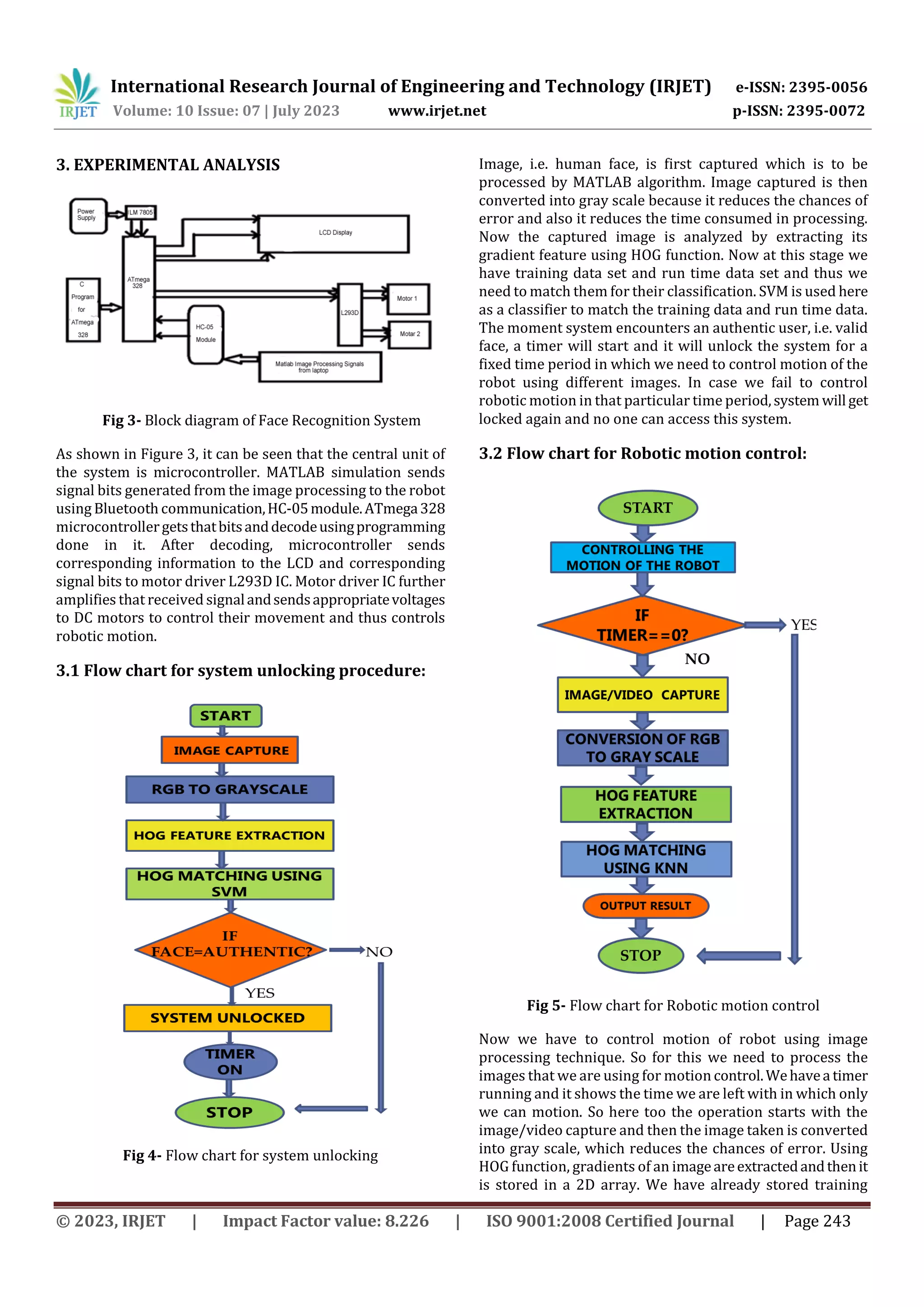
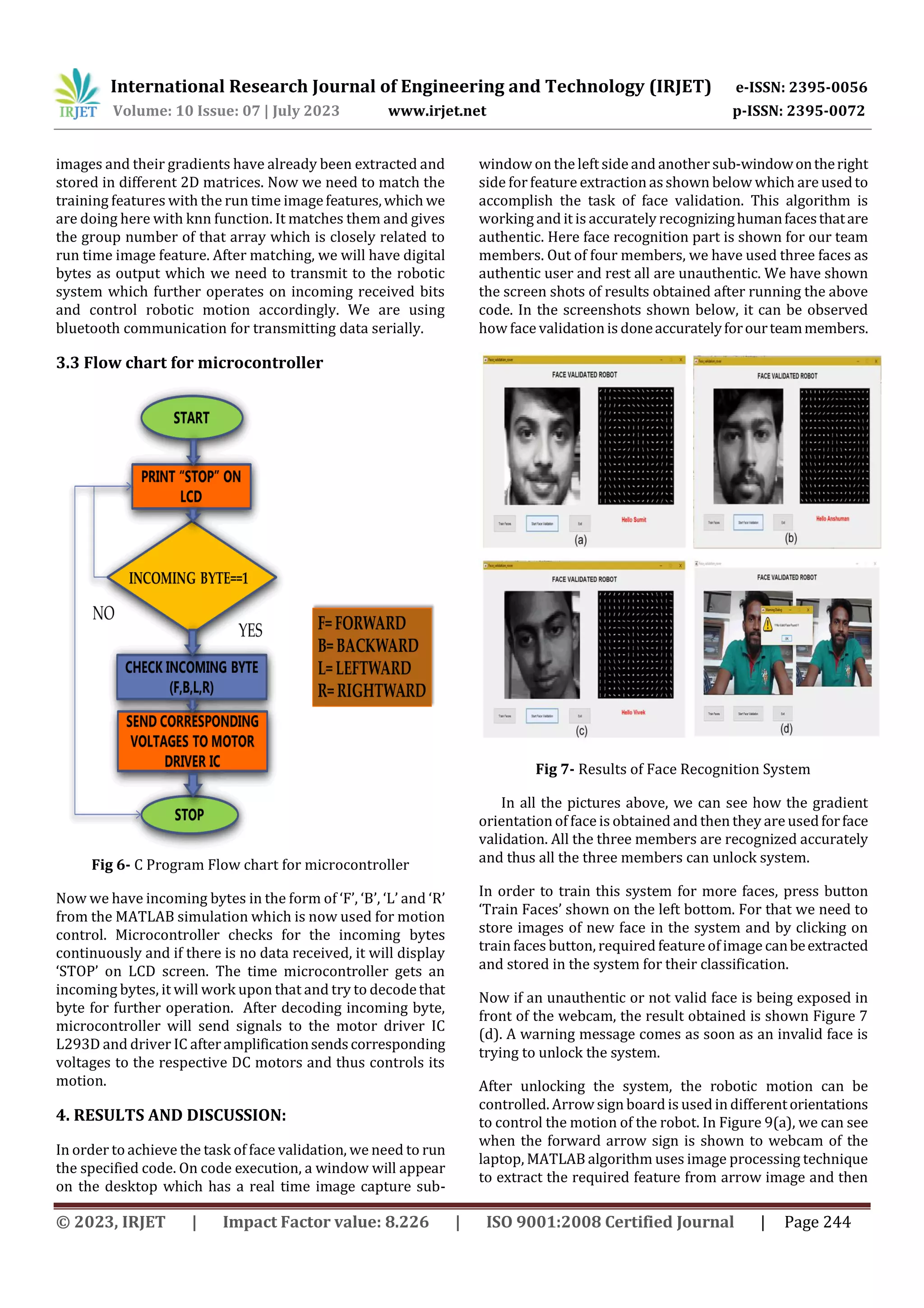
This document describes a face recognition system used to control a robotic system. The system works in two stages: first, face recognition is used to unlock the system by validating a user's face. Then, different navigation images are used to control the robot's motion. Face recognition is implemented using support vector machine (SVM), histogram of oriented gradients (HOG), and k-nearest neighbors (KNN) algorithms in MATLAB. The process is based on machine learning concepts where the system is trained in a supervised manner to recognize faces and control the robot.