Download to read offline
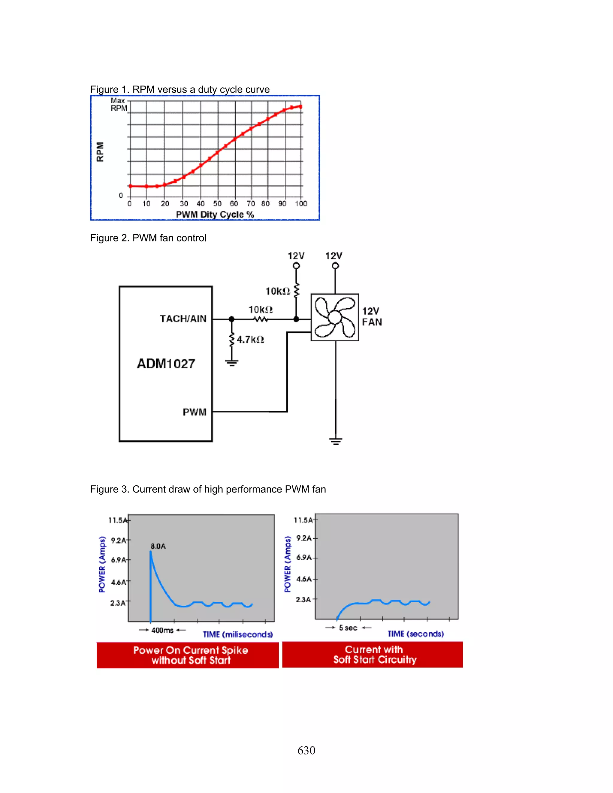
![627 Baltimore, Maryland NOISE-CON 2004 2004 July 12-14 Implementing PWM Fan Speed Control to Decrease Energy Consumption, Reduce Acoustics, and Increase Fan Performance. Abe Arredondo Partha Roy Erin Wofford JMC Products 13015 A Metropolitan Dr Austin TX 78758 USA 1. OBJECTIVE In this paper you will learn the implementation of Pulse Width Modulation (PWM) fan speed control and how it can decrease energy consumption and reduce acoustics while providing wider operational speed bandwidth. Regulating fan speed according to the temperature inside an enclosure is the most effective method utilized to cool electronic products. PWM is the preferred approach to regulating motor speed for three main reasons. First, PWM is energy efficient since it doesn't generate additional heat. Second, it improves the acoustics of the fan with high frequency driving signals. Finally, it provides thermal engineers with added operational speed bandwidth because the fan can run at either remarkably low or high speeds. 2. APPLYING PWM Pulse Width Modulation (PWM) refers to the method of applying a signal to a fan that will vary the width of a signal applied to the 4th wire. An 80% duty cycle indicates that the fan is "on" 80% of the time and "off" 20% of the time. A 50% duty cycle signal indicates that the fan is "on" 50% of the time and "off" 50% of the time (similar to a perfect square wave). On a PWM fan, the 4th wire consists of the PWM line, which will be directly proportional to the speed of the fan. That is to say, a high duty cycle will produce high speeds and a low duty cycle will produce idle speeds. See Figure 1 for a PWM duty cycle versus an RPM curve. During normal operation within an electronics enclosure a thermal controller residing on the motherboard or controlling electronics can command multiple fans to achieve a desired RPM target by adjusting the PWM duty cycle. PWM controllers for brushless DC motors are available from companies [1] such as, Analog Devices (ADT7460), Microchip Technology (TC664), and National Semiconductor (LM63). Figure 2 shows the typical interconnection of a PWM controller and 4-wire PWM fan where the fan accepts a PWM control signal to change motor speed and replies with a tachometer speed signal in return. As a result, a simple automatic closed loop speed system is formed. With closed loop speed control, the tolerance of the fan PWM duty cycle vs. RPM speed curve can be within 20% speed tolerance at idle and 10% speed tolerance at the maximum fan speed. 3. DECREASING ENERGY CONSUMPTION WITH PWM This section describes a new high performance PWM fan technology that includes a soft start circuit that monitors current and limits the current intake of a high performance fan upon start up, at 100% duty cycle, or locked rotor condition. In addition, we will discuss how to decrease energy consumption by selecting the most suitable motor configuration for your fan. A. Soft Start Current Monitor Traditionally, implementing PWM fan speed control into high performance fans caused start- up energy consumption concerns for a designer. The first concern with high performance PWM](https://image.slidesharecdn.com/bb97ca94-1b0a-4226-9967-6743dbf5c774-150712204235-lva1-app6891/75/Implementing-PWM-Fan-Speed-Control-1-2048.jpg)
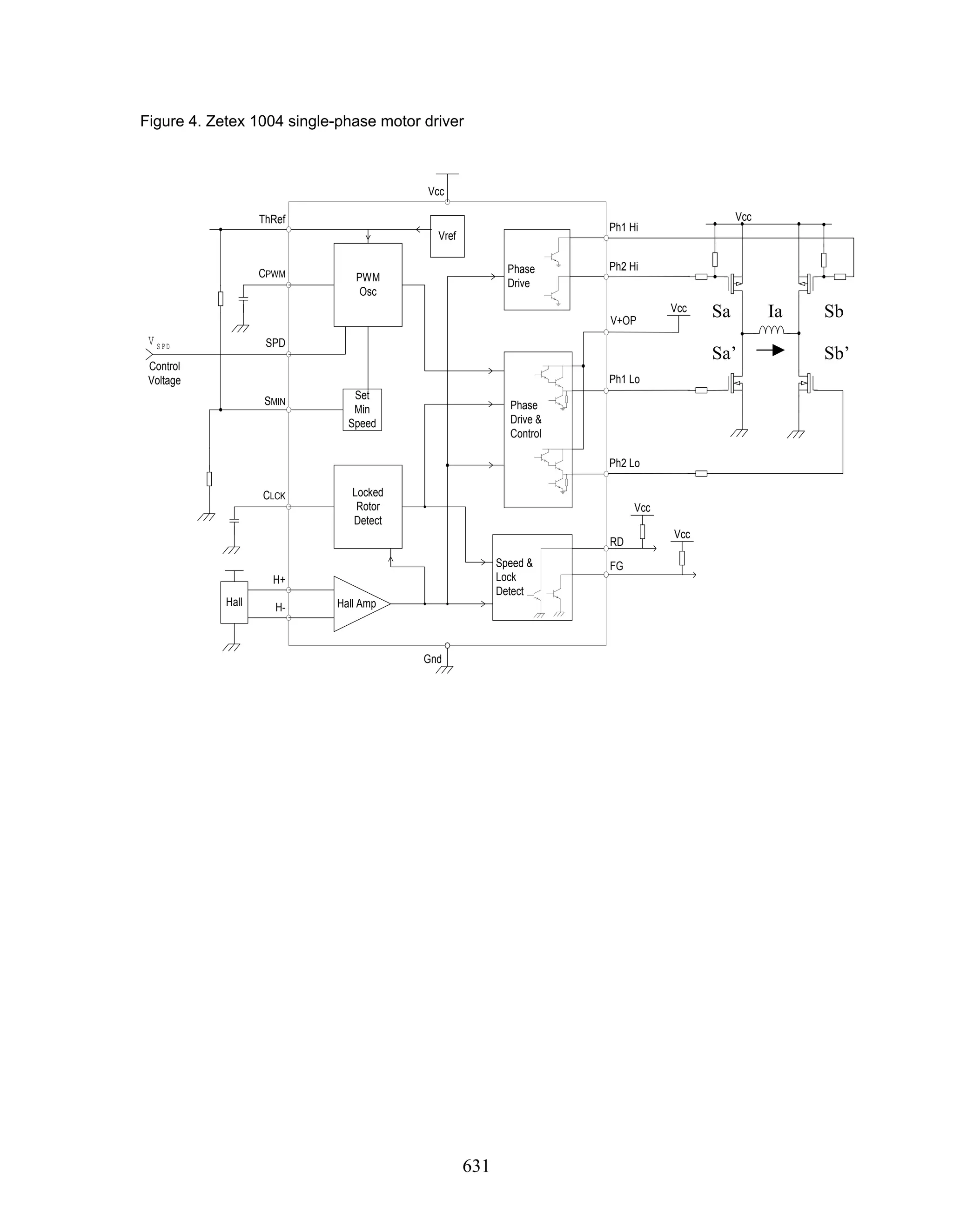
![628 fans is that the designer must consider the worst-case possibility of a fan, or a group of fans, starting at 100% duty cycle and drawing four to five times more current for several hundred milliseconds than the current drawn under normal steady state conditions, as shown in Figure 3. The second concern a designer must consider is the current spike when the fan consists of a locked rotor signal. A fan is in locked rotor condition when a foreign object is logged in the fan blades impeding the rotor to turn. To prevent an over current condition, most fans contain an auto restart feature that turns the fan off and attempts to restart the fan every three seconds. The designer must consider the worst-case current draw condition again when a high performance PWM fan attempts to restart at 100% duty cycle every three seconds, again drawing four to five times more current for a brief period of time. The cause of the high start-up current in a PWM fan is due to a back EMF in the fan circuitry. When a motor is running under steady state conditions, a back EMF counters the applied voltage and holds the current in check. The back EMF is proportional to the rotational speed of the fan. During a start-up condition the fan starts up from a resting position of 0 RPM and progressively increases from low to high values. The back EMF is consequently low and therefore the current reaches a very high level for the first few hundred milliseconds before the fans speeds up and reaches a steady state condition. By implementing a soft start circuitry into the PWM fan, the in rush current can be controlled and therefore decrease energy consumption of the fan at start-up. Figure 3 shows the results of how a current monitor in series with the motor can provide instant current feedback to the motor controller preventing large current spikes. As the current flow increases, the current monitor senses a proportionally high voltage drop and amplifies it into an output voltage that is fed back to the motor controller IC; thus, throttling the current back before it reaches too high of a value. B. Motor Configuration PWM fan designs require specialty high frequency controllers that can drive both 2-phase and single-phase motors. Both motor configurations are brushless DC type and contain a 4-pole magnet. A 2-phase brushless DC motor is found in legacy fan motor designs. This is where the motor controller drives 2 phases separately and opposite of each other within a 4-pole magnet. To decrease the energy consumption of a fan, it is greatly recommended that the fan motor stator be wound as a single-phase motor. Updated motor drivers, such as Zetex ZXMB1004 [2], drive single-phase brushless DC motors. In the PWM single phase switching scheme [3], as shown in Figure 4, a phase voltage is applied by steadily turning on Sa while switching Sb’ by pulse width modulating. While both Sa and Sb’ are in the driving state, current Ia increases. For continued ratio, a negative A-phase voltage is applied by steadily turning on Sb while modulating switch Sa’. Only two switching events occur in a PWM period. Because of the full utilization of the stator windings, this motor scheme decreases the energy consumption That is, all the windings of the motor are used at all times such that the efficiency of a single phase motor is increased over a 2- phase motor by 10% to 15%. 4. ACOUSTIC ADVANTAGE OF PWM FANS The most dominant source of acoustic fan noise is turbulent airflow, which is caused by fan operation at full speed [4]. Employing fan speed control, where the fan is operating primarily at low speed rather than full speed, minimizes this noise. The idle speed of a PWM fan can be as low as approximately 500 RPM’s. A well-balanced and lubricated fan idling at 500 RPM’s cannot be heard and may also be undetectable by acoustic measurement equipment. Motor switching is another source of fan noise when utilizing a PWM fan. The motor switching noise, which is the frequency commutation at which the fan motor is turned on and off, also affects the acoustics of a PWM fan. The motor switching noise of the fan is due to the clicking and whistling noise of a brushless DC motor commutation for every revolution. The motor commutation noise is most noticeable when the PWM signal is driven at low frequencies such at 30 Hz. The motor switching noise is eliminated when the fan is driven at higher frequencies of 25 KHz. Let's imagine that that you apply a 50% duty cycle signal to a fan at a low frequency of 30 Hz. This results in 30 square waves per second. The low frequency of 30 Hz will result in an acoustically loud fan due to the motor switching noise of the fan. Now let's imagine that you apply](https://image.slidesharecdn.com/bb97ca94-1b0a-4226-9967-6743dbf5c774-150712204235-lva1-app6891/75/Implementing-PWM-Fan-Speed-Control-2-2048.jpg)
![629 a 50% duty cycle signal to the fan at a high frequency of 25 KHz. This results in 25,000 square waves per second. A human can only hear frequencies up to 20 KHz, which means that the frequency of 25 KHz being applied to the PWM fan makes the motor switching noise so quiet that when the fan runs at low speed, it cannot be heard. 5. ENHANCED PERFORMANCE OF PWM FANS Single-phase PWM DC brushless motors provide thermal engineers with more operational speed bandwidth because the low speed, or idle speed, is two times lower than a traditional voltage-controlled fan. The idle speed of a PWM fan can be as low as approximately 500 RPM’s and the high speed is approximately 10% faster because of motor efficiencies. As described above in paragraph 3B on motor configuration, brushless DC PWM motors provide enhanced performance because of the H bridge type single-phase switching motor configuration. The efficiency of this type of motor is improved over a traditional 2-phase motor by reducing the current consumption by 10% to 15%. 4. SUMMARY This paper has shown you the implementation of PWM fan speed control and how it can decrease energy consumption and reduce acoustics while providing wider operational speed bandwidth. In addition, this paper has described a new high performance PWM fan technology that includes a soft start circuit that monitors current and limits the current intake of a high performance fan. We anticipate that each enclosure or application will require a customized thermal solution approach. General equations and rules have not yet been developed. PWM fan applications include computer systems motherboards, chassis systems fans, and microprocessor active heat sinks for consumer electronics such as televisions, TV recording set top boxes, telecommunications and automotive applications. One PWM fan model can replace many models of similar top speed and CFM fans. Currently, designers require a multitude of different temperature and RPM curves, which will generate many different fan models. Thus, a designer’s logistical processes can become very complicated. However, when using only one PWM fan, a designer can program their desired temperature/RPM curve by simply changing the PWM controller software. REFERENCES [1] All company and product names that appear in this paper are the trademarks or service marks of their respective owners, including: Zetex (ZXMB1004), Analog Devices (ADT7460), Microchip Technology (TC664), and National Semiconductor (LM63). [2] Armstrong L. March 2004. Zetex (ZXMB1004) single-phase brushless DC motor pre-driver http://www.zetex.com [3] Ohm, D. (April/May 2004). PWM Schemes and commutation methods for brushless DC Motor drives. e-Drive, Magazine of electric Motor and Drive Technology, Volume 5, Issue 2. pp 19. [4] Microchip. Acoustic Noise Reduction. Retrieved July, 2003. from http://www.microchip.com/1010/index.htm [5] Mary Burke. Analog Devices International. Circuit for driving a fan with high-frequency PWM. 1995. Retrieved April 28, 2004 from http://www.analog.com/library/analogDialogue/archives/38-02/fan_speed.html](https://image.slidesharecdn.com/bb97ca94-1b0a-4226-9967-6743dbf5c774-150712204235-lva1-app6891/75/Implementing-PWM-Fan-Speed-Control-3-2048.jpg)

This document discusses implementing pulse width modulation (PWM) fan speed control to decrease energy consumption, reduce noise, and increase fan performance. PWM regulates fan speed according to temperature, which is more efficient than constant speed. It generates less heat, improves acoustics with high-frequency signals, and provides more speed control bandwidth. Implementing a soft start circuit and using a single-phase motor configuration can further reduce energy usage by limiting current spikes during start up and increasing motor efficiency. Operating fans at lower PWM frequencies eliminates audible motor switching noise. Overall, PWM control allows fans to operate more efficiently across a wider speed range while decreasing noise and power consumption.