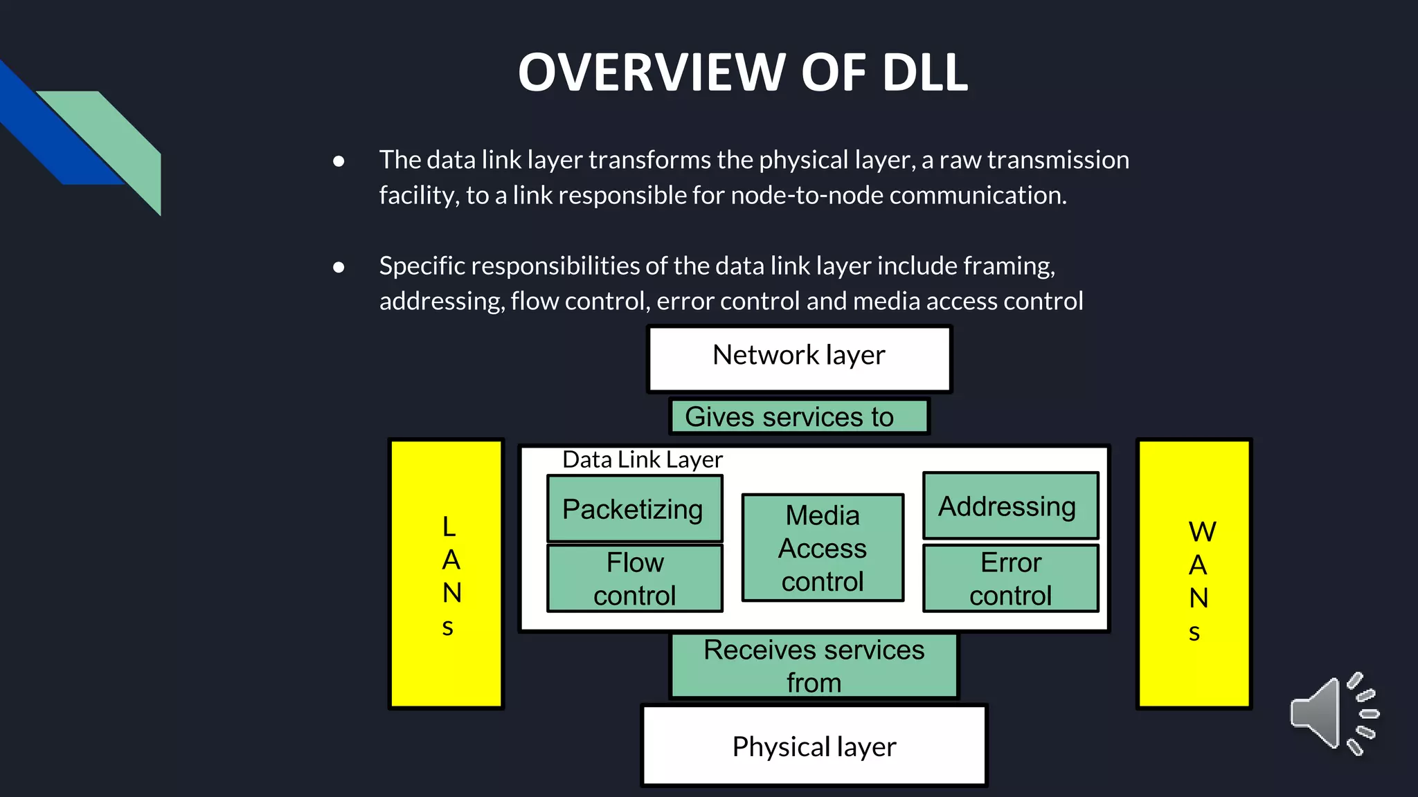
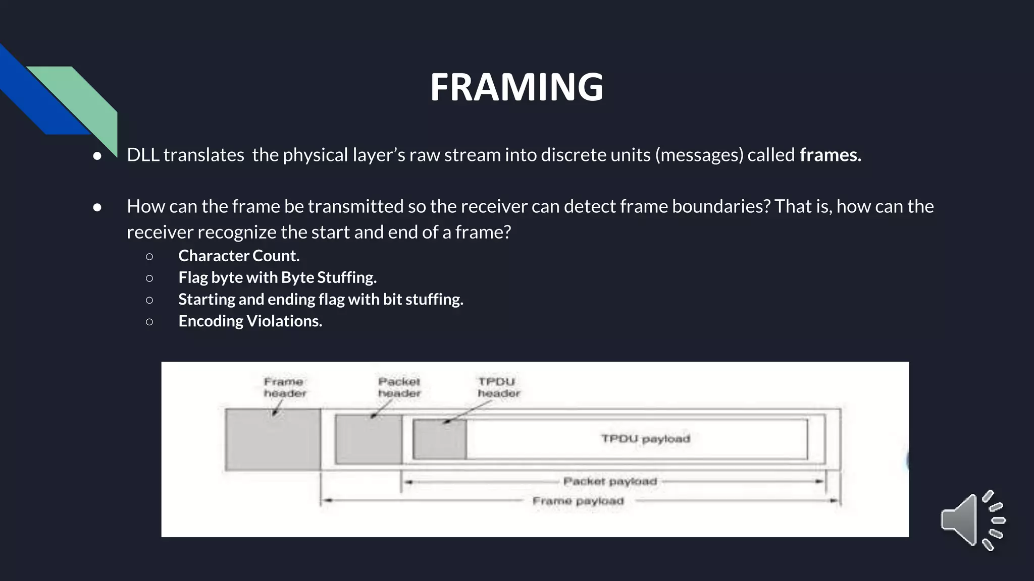
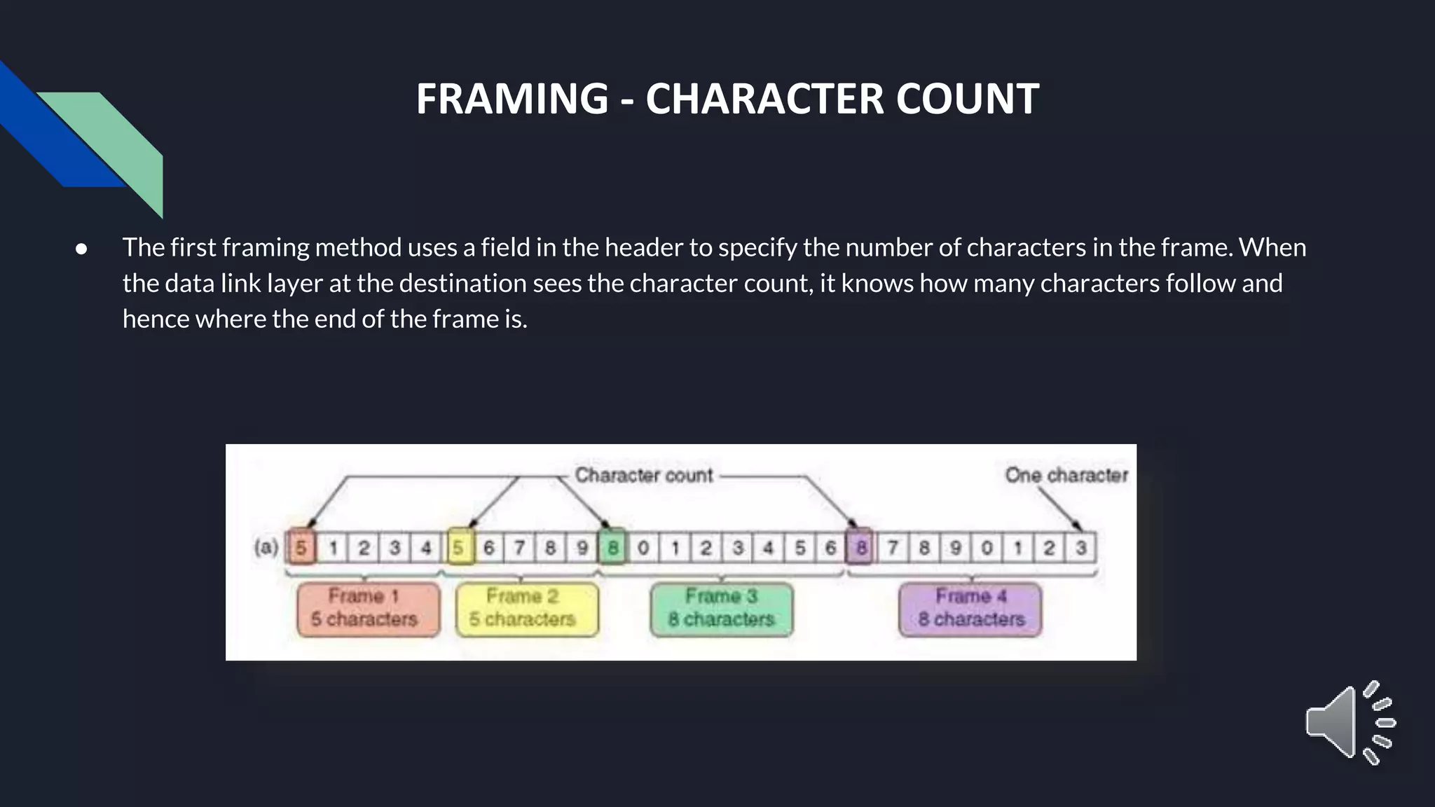
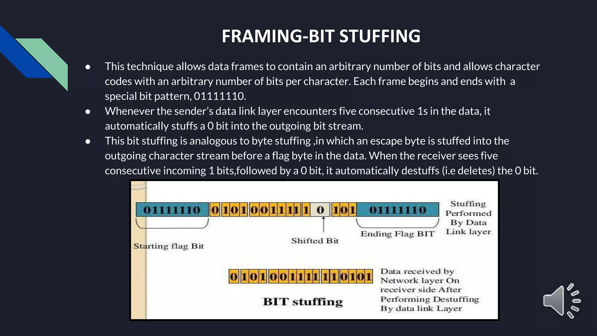
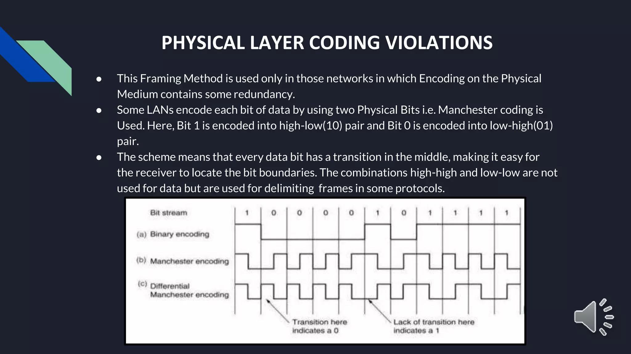
INTRODUCTION TO DATA LINK LAYER DONE BY: NAME: Shashank HP SJC Inititute of Technology Data Communication – 18CS46
Physical layer Gives services to Receives services from OVERVIEW OF DLL ● The data link layer transforms the physical layer, a raw transmission facility, to a link responsible for node-to-node communication. ● Specific responsibilities of the data link layer include framing, addressing, flow control, error control and media access control L A N s W A N s Network layer Packetizing Flow control Media Access control Addressing Error control Data Link Layer
DLL DESIGN ● Services Provided to the Network Layer: The network layer wants to send packets to its neighbours without worrying about the details of it in one piece. ● Framing: Group the physical layer bit stream into units called frames. Frames are nothing more than “packets” or “messages”. By convention , we use the term “frames” when discussing DLL. ● Error Control: Sender checksums the frame and transmits checksums together with data. Receiver re-computes the checksum and compares it with the received value. ● Flow control: Prevent a fast sender from overwhelming a slower receiver.
SERVICES PROVIDED TO THE NETWORK LAYER ● The function of the data link layer is to provide services to the network layer. ● The principal service is transferring data from the network layer on the source machine to the network layer on the destination machine. ● The data link layer can be designed to offer various services. The actual services offered can vary from system.
FRAMING ● DLL translates the physical layer’s raw stream into discrete units (messages) called frames. ● How can the frame be transmitted so the receiver can detect frame boundaries? That is, how can the receiver recognize the start and end of a frame? ○ Character Count. ○ Flag byte with Byte Stuffing. ○ Starting and ending flag with bit stuffing. ○ Encoding Violations.
FRAMING - CHARACTER COUNT ● The first framing method uses a field in the header to specify the number of characters in the frame. When the data link layer at the destination sees the character count, it knows how many characters follow and hence where the end of the frame is.
FRAMING - BYTE STUFFING ● Use reserved characters to indicate the start and end of a frame. For instance, use the two-character sequence DLE STX(Data-Link Escape, Start of TeXt) to signal the beginning of a frame, and the sequence DLE ETX(End of TeXt) to flag the frame’s end. ● The second framing method, Starting and ending character stuffing, gets around the problem of resynchronization after an error by having each frame start with the sequence DLE ETX. ● EXAMPLE: If the frame contained “A B DLE D E DLE”, the characters transmitted over the channel would be “DLE STX A B DLE DLE D E DLE DLE DLE ETX”
FRAMING-BIT STUFFING ● This technique allows data frames to contain an arbitrary number of bits and allows character codes with an arbitrary number of bits per character. Each frame begins and ends with a special bit pattern, 01111110. ● Whenever the sender’s data link layer encounters five consecutive 1s in the data, it automatically stuffs a 0 bit into the outgoing bit stream. ● This bit stuffing is analogous to byte stuffing ,in which an escape byte is stuffed into the outgoing character stream before a flag byte in the data. When the receiver sees five consecutive incoming 1 bits,followed by a 0 bit, it automatically destuffs (i.e deletes) the 0 bit.
PHYSICAL LAYER CODING VIOLATIONS ● This Framing Method is used only in those networks in which Encoding on the Physical Medium contains some redundancy. ● Some LANs encode each bit of data by using two Physical Bits i.e. Manchester coding is Used. Here, Bit 1 is encoded into high-low(10) pair and Bit 0 is encoded into low-high(01) pair. ● The scheme means that every data bit has a transition in the middle, making it easy for the receiver to locate the bit boundaries. The combinations high-high and low-low are not used for data but are used for delimiting frames in some protocols.
ERROR CONTROL There are many reasons such as noise, cross-talk etc., which may help data to get corrupted during transmission. Error control is concerned with insuring that all frames are eventually delivered (possibly in order) to destination. Data-link layer uses some error control mechanism to ensure that frames (data bit streams) are transmitted with certain level of accuracy. But to understand how errors is controlled, it is essential to know what types of errors may occur. Types of Errors There may be three types of errors: Single bit error Multiple bits error Burst error
Error Detection Errors in the received frames are detected by means of Parity Check and Cyclic Redundancy Check (CRC). In both cases, few extra bits are sent along with actual data to confirm that bits received at other end are same as they were sent. If the counter- check at receiver’ end fails, the bits are considered corrupted. • Parity Check One extra bit is sent along with the original bits to make number of 1s either even in case of even parity, or odd in case of odd parity. For example, if even parity is used and number of 1s is even then one bit with value 0 is added. This way number of 1s remains even. If the number of 1s is odd, to make it even a bit with value 1 is added.
● Cyclic Redundancy Check (CRC) CRC is a different approach to detect if the received frame contains valid data. This technique involves binary division of the data bits being sent. The divisor is generated using polynomials. The sender performs a division operation on the bits being sent and calculates the remainder. Before sending the actual bits, the sender adds the remainder at the end of the actual bits. Actual data bits plus the remainder is called a codeword. The sender transmits data bits as codewords. At the other end, the receiver performs division operation on codewords using the same CRC divisor. If the remainder contains all zeros the data bits are accepted, otherwise it is considered as there some data corruption occurred in transit.
Error Correction In the digital world, error correction can be done in two ways: ● Backward Error Correction When the receiver detects an error in the data received, it requests back the sender to retransmit the data unit. ● Forward Error Correction When the receiver detects some error in the data received, it executes error-correcting code, which helps it to auto-recover and to correct some kinds of errors. The first one, Backward Error Correction, is simple and can only be efficiently used where retransmitting is not expensive. For example, fiber optics. But in case of wireless transmission retransmitting may cost too much. In the latter case, Forward Error Correction is used. To correct the error in data frame, the receiver must know exactly which bit in the frame is corrupted. To locate the bit in error, redundant bits are used as parity bits for error detection. For example, we take ASCII words (7 bits data), then there could be 8 kind of information we need: first seven bits to tell us which bit is error and one more bit to tell that there is no error.
FLOW CONTROL ● Flow control deals with throttling the speed of the sender to match that of the receiver. ● Two Approaches: ○ Feedback-based flow control, the receiver send back information to the sender giving it permission to send more data or atleast telling the sender how the receiver is doing. ○ rate -based flow control, the protocol has a built-in mechanism that limits the rate at which senders may transmit data, without using feedback from the receiver. ● Various Flow Control schemes uses a common protocol that contains well-defined rules about when a sender may transmit the next frame. These rules often prohibit frames from being sent until the receiver has granted permission, either implicitly or explicitly.
Network Layer Features With its standard functionalities, various features as: ● Quality of service management ● Load balancing and link management ● Security ● Interrelation of different protocols and subnets with different schema. ● Different logical network design over the physical network design. ● L3 VPN and tunnels can be used to provide end to end dedicated connectivity.
THANK YOU!

Introduction to data link layer

  • 1.
    INTRODUCTION TO DATALINK LAYER DONE BY: NAME: Shashank HP SJC Inititute of Technology Data Communication – 18CS46
  • 2.
    Physical layer Gives servicesto Receives services from OVERVIEW OF DLL ● The data link layer transforms the physical layer, a raw transmission facility, to a link responsible for node-to-node communication. ● Specific responsibilities of the data link layer include framing, addressing, flow control, error control and media access control L A N s W A N s Network layer Packetizing Flow control Media Access control Addressing Error control Data Link Layer
  • 3.
    DLL DESIGN ● ServicesProvided to the Network Layer: The network layer wants to send packets to its neighbours without worrying about the details of it in one piece. ● Framing: Group the physical layer bit stream into units called frames. Frames are nothing more than “packets” or “messages”. By convention , we use the term “frames” when discussing DLL. ● Error Control: Sender checksums the frame and transmits checksums together with data. Receiver re-computes the checksum and compares it with the received value. ● Flow control: Prevent a fast sender from overwhelming a slower receiver.
  • 4.
    SERVICES PROVIDED TOTHE NETWORK LAYER ● The function of the data link layer is to provide services to the network layer. ● The principal service is transferring data from the network layer on the source machine to the network layer on the destination machine. ● The data link layer can be designed to offer various services. The actual services offered can vary from system.
  • 5.
    FRAMING ● DLL translatesthe physical layer’s raw stream into discrete units (messages) called frames. ● How can the frame be transmitted so the receiver can detect frame boundaries? That is, how can the receiver recognize the start and end of a frame? ○ Character Count. ○ Flag byte with Byte Stuffing. ○ Starting and ending flag with bit stuffing. ○ Encoding Violations.
  • 6.
    FRAMING - CHARACTERCOUNT ● The first framing method uses a field in the header to specify the number of characters in the frame. When the data link layer at the destination sees the character count, it knows how many characters follow and hence where the end of the frame is.
  • 7.
    FRAMING - BYTESTUFFING ● Use reserved characters to indicate the start and end of a frame. For instance, use the two-character sequence DLE STX(Data-Link Escape, Start of TeXt) to signal the beginning of a frame, and the sequence DLE ETX(End of TeXt) to flag the frame’s end. ● The second framing method, Starting and ending character stuffing, gets around the problem of resynchronization after an error by having each frame start with the sequence DLE ETX. ● EXAMPLE: If the frame contained “A B DLE D E DLE”, the characters transmitted over the channel would be “DLE STX A B DLE DLE D E DLE DLE DLE ETX”
  • 8.
    FRAMING-BIT STUFFING ● Thistechnique allows data frames to contain an arbitrary number of bits and allows character codes with an arbitrary number of bits per character. Each frame begins and ends with a special bit pattern, 01111110. ● Whenever the sender’s data link layer encounters five consecutive 1s in the data, it automatically stuffs a 0 bit into the outgoing bit stream. ● This bit stuffing is analogous to byte stuffing ,in which an escape byte is stuffed into the outgoing character stream before a flag byte in the data. When the receiver sees five consecutive incoming 1 bits,followed by a 0 bit, it automatically destuffs (i.e deletes) the 0 bit.
  • 9.
    PHYSICAL LAYER CODINGVIOLATIONS ● This Framing Method is used only in those networks in which Encoding on the Physical Medium contains some redundancy. ● Some LANs encode each bit of data by using two Physical Bits i.e. Manchester coding is Used. Here, Bit 1 is encoded into high-low(10) pair and Bit 0 is encoded into low-high(01) pair. ● The scheme means that every data bit has a transition in the middle, making it easy for the receiver to locate the bit boundaries. The combinations high-high and low-low are not used for data but are used for delimiting frames in some protocols.
  • 10.
    ERROR CONTROL There aremany reasons such as noise, cross-talk etc., which may help data to get corrupted during transmission. Error control is concerned with insuring that all frames are eventually delivered (possibly in order) to destination. Data-link layer uses some error control mechanism to ensure that frames (data bit streams) are transmitted with certain level of accuracy. But to understand how errors is controlled, it is essential to know what types of errors may occur. Types of Errors There may be three types of errors: Single bit error Multiple bits error Burst error
  • 11.
    Error Detection Errors inthe received frames are detected by means of Parity Check and Cyclic Redundancy Check (CRC). In both cases, few extra bits are sent along with actual data to confirm that bits received at other end are same as they were sent. If the counter- check at receiver’ end fails, the bits are considered corrupted. • Parity Check One extra bit is sent along with the original bits to make number of 1s either even in case of even parity, or odd in case of odd parity. For example, if even parity is used and number of 1s is even then one bit with value 0 is added. This way number of 1s remains even. If the number of 1s is odd, to make it even a bit with value 1 is added.
  • 12.
    ● Cyclic RedundancyCheck (CRC) CRC is a different approach to detect if the received frame contains valid data. This technique involves binary division of the data bits being sent. The divisor is generated using polynomials. The sender performs a division operation on the bits being sent and calculates the remainder. Before sending the actual bits, the sender adds the remainder at the end of the actual bits. Actual data bits plus the remainder is called a codeword. The sender transmits data bits as codewords. At the other end, the receiver performs division operation on codewords using the same CRC divisor. If the remainder contains all zeros the data bits are accepted, otherwise it is considered as there some data corruption occurred in transit.
  • 13.
    Error Correction In thedigital world, error correction can be done in two ways: ● Backward Error Correction When the receiver detects an error in the data received, it requests back the sender to retransmit the data unit. ● Forward Error Correction When the receiver detects some error in the data received, it executes error-correcting code, which helps it to auto-recover and to correct some kinds of errors. The first one, Backward Error Correction, is simple and can only be efficiently used where retransmitting is not expensive. For example, fiber optics. But in case of wireless transmission retransmitting may cost too much. In the latter case, Forward Error Correction is used. To correct the error in data frame, the receiver must know exactly which bit in the frame is corrupted. To locate the bit in error, redundant bits are used as parity bits for error detection. For example, we take ASCII words (7 bits data), then there could be 8 kind of information we need: first seven bits to tell us which bit is error and one more bit to tell that there is no error.
  • 14.
    FLOW CONTROL ● Flowcontrol deals with throttling the speed of the sender to match that of the receiver. ● Two Approaches: ○ Feedback-based flow control, the receiver send back information to the sender giving it permission to send more data or atleast telling the sender how the receiver is doing. ○ rate -based flow control, the protocol has a built-in mechanism that limits the rate at which senders may transmit data, without using feedback from the receiver. ● Various Flow Control schemes uses a common protocol that contains well-defined rules about when a sender may transmit the next frame. These rules often prohibit frames from being sent until the receiver has granted permission, either implicitly or explicitly.
  • 15.
    Network Layer Features Withits standard functionalities, various features as: ● Quality of service management ● Load balancing and link management ● Security ● Interrelation of different protocols and subnets with different schema. ● Different logical network design over the physical network design. ● L3 VPN and tunnels can be used to provide end to end dedicated connectivity.
  • 16.