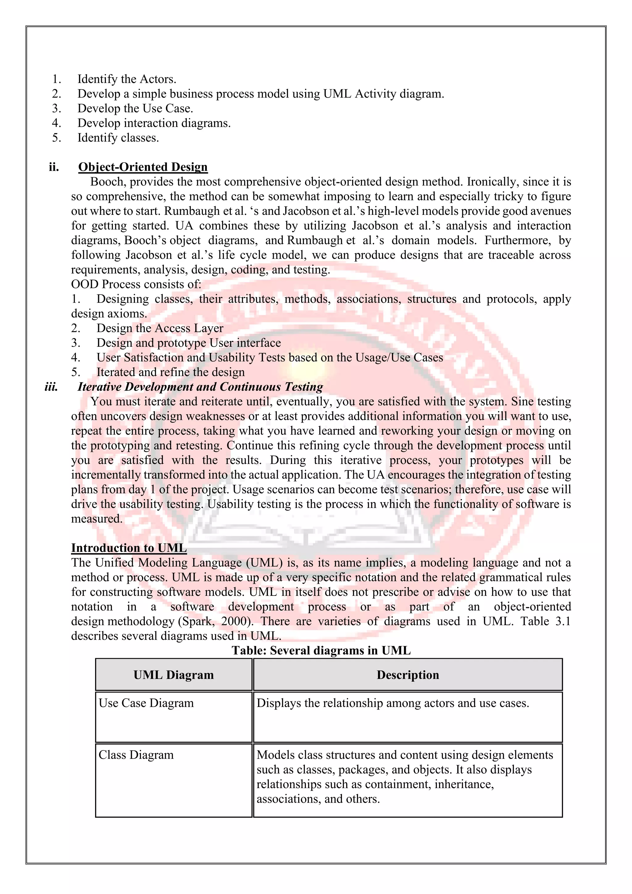
Object Oriented Analysis and Design M.Sc. Computer Science III Semester MS. Arati Singh Department of Computer Science Shri Shankaracharya Mahavidyalaya Junwani
ObjectOrientedAnalysis andDesign Unit-2 UnifiedApproach The Unified Approach (UA) is a methodology for software development that is proposed by the author Ali Bahrami (1999). The UA, based on methodologies by Booch, Rumbaugh, and Jacobson, tries to combine the best practices, processed, and guidelines along with the Object Management Group’s unified modeling language. The unified modeling language (UML) is a set of notations and conventions used to describe and model an application. However, the UML does not specify a methodology or what steps to follow to develop an application; that would be the task of the UA. The heart of the UA is Jacobson’s use case. The use case represents a typical interaction between a user and a computer system to capture the users’ goals and needs. In its simplest usage, you capture a use case by talking to typical users and discussing the various ways they might want to use the system. The use cases are entered into all other activities of the UA. The UA establishes a unifying and unitary framework around their works by utilizing the UML to describe the model and document the software development process. The idea behind the UA is not to introduce yet another methodology. The main motivation here is to combine the best practices, processes, methodologies, and guidelines along with UML notations and diagrams for better understanding of object-oriented concepts and system development. Figure: The processes and components of the unified approach The unified approach to software development revolves around (but is not limited to) to the following processes and concepts. The processes are: 1. Use-case driven development 2. Object-oriented analysis 3. Object-oriented design 4. Incremental development and prototyping 5. Continuous testing The UA allows iterative development by allowing you to go back and forth between the design and the modeling or analysis phases. It makes backtracking very easy and departs from the linear waterfall process, which allows no form of back tracking. i. Object-Oriented Analysis Analysis is the process of extracting the needs of a system and what the system must do to satisfy the users’ requirements. The goal of object-oriented analysis is to first understand the domain of the problem and the system’s responsibilities by understanding how the users use or will use the system. It concentrates on describing what the system does rather than how it does it. Separating the behavior of a system from the way it is implemented require viewing the system from the user’s perspective rather than that of the machine. OOA process consists of the following steps:
1. Identify the Actors. 2. Develop a simple business process model using UML Activity diagram. 3. Develop the Use Case. 4. Develop interaction diagrams. 5. Identify classes. ii. Object-Oriented Design Booch, provides the most comprehensive object-oriented design method. Ironically, since it is so comprehensive, the method can be somewhat imposing to learn and especially tricky to figure out where to start. Rumbaugh et al. ‘s and Jacobson et al.’s high-level models provide good avenues for getting started. UA combines these by utilizing Jacobson et al.’s analysis and interaction diagrams, Booch’s object diagrams, and Rumbaugh et al.’s domain models. Furthermore, by following Jacobson et al.’s life cycle model, we can produce designs that are traceable across requirements, analysis, design, coding, and testing. OOD Process consists of: 1. Designing classes, their attributes, methods, associations, structures and protocols, apply design axioms. 2. Design the Access Layer 3. Design and prototype User interface 4. User Satisfaction and Usability Tests based on the Usage/Use Cases 5. Iterated and refine the design iii. Iterative Development and Continuous Testing You must iterate and reiterate until, eventually, you are satisfied with the system. Sine testing often uncovers design weaknesses or at least provides additional information you will want to use, repeat the entire process, taking what you have learned and reworking your design or moving on the prototyping and retesting. Continue this refining cycle through the development process until you are satisfied with the results. During this iterative process, your prototypes will be incrementally transformed into the actual application. The UA encourages the integration of testing plans from day 1 of the project. Usage scenarios can become test scenarios; therefore, use case will drive the usability testing. Usability testing is the process in which the functionality of software is measured. Introduction to UML The Unified Modeling Language (UML) is, as its name implies, a modeling language and not a method or process. UML is made up of a very specific notation and the related grammatical rules for constructing software models. UML in itself does not prescribe or advise on how to use that notation in a software development process or as part of an object-oriented design methodology (Spark, 2000). There are varieties of diagrams used in UML. Table 3.1 describes several diagrams used in UML. Table: Several diagrams in UML UML Diagram Description Use Case Diagram Displays the relationship among actors and use cases. Class Diagram Models class structures and content using design elements such as classes, packages, and objects. It also displays relationships such as containment, inheritance, associations, and others.
UML Diagram Description State Diagram Displays the entire sequence of states that an object undergoes in response to received stimuli, together with the object's responses and actions Sequence Diagram Displays the time sequence of the objects participating in the interaction. This consists of the vertical dimension (time) and horizontal dimension (different objects). Collaboration Diagram Displays an interaction organized around the objects and their links to one another. Numbers are used to show the sequence of messages. Activity Diagram Displays a special state diagram where most of the states are action states and most of the transitions are triggered by completion of the actions in the source states. This diagram focuses on flows driven by internal processing. Component Diagram Displays the high-level packaged structure of the code itself. Dependencies among components are shown, including source code components, binary code components, and executable components. Package Diagram Shows how classes can be divided into modules. It also displays the high-level relationships between packages, of the system, or a specific subsection. Deployment Diagram Displays the configuration of run-time processing elements and the software components, processes, and objects that reside within them. UML provides us with a very simple approach to modeling the system requirements. There are two primary views of the problem that help the developers analyze and organize a clear definition of the basic functionality of the system. Through Use Case Diagrams and Sequence Diagrams we can easily model most of the system requirements. The result of these two graphical views is a rather complete specification of the system functions, a general description of the processing involved in each function, a first cut at the objects involved in providing the functionality, and a general scheme for the communication between the objects. UML is a visual language that lets you to model processes, software, and systems to express the design of system architecture. It is a standard language for designing and documenting a system in an object oriented manner that allow technical architects to communicate with developer. It is defined as set of specifications created and distributed by Object Management Group. UML is extensible and scalable.
UML-BasicNotations UML is popular for its diagrammatic notations. We all know that UML is for visualizing, specifying, constructing and documenting the components of software and non-software systems. Hence, visualization is the most important part which needs to be understood and remembered. UML notations are the most important elements in modeling. Efficient and appropriate use of notations is very important for making a complete and meaningful model. The model is useless, unless its purpose is depicted properly. Hence, learning notations should be emphasized from the very beginning. Different notations are available for things and relationships. UML diagrams are made using the notations of things and relationships. Extensibility is another important feature which makes UML more powerful and flexible. The chapter describes basic UML notations in detail. This is just an extension to the UML building block section discussed in Chapter Two. Structural Things Graphical notations used in structural things are most widely used in UML. These are considered as the nouns of UML models. Following are the list of structural things. • Classes • Object • Interface • Collaboration • Use case • Active classes • Components • Nodes ClassNotation UML class is represented by the following figure. The diagram is divided into four parts. • The top section is used to name the class. • The second one is used to show the attributes of the class. • The third section is used to describe the operations performed by the class. • The fourth section is optional to show any additional components. Classes are used to represent objects. Objects can be anything having properties and responsibility. ObjectNotation The object is represented in the same way as the class. The only difference is the name which is underlined as shown in the following figure.
As the object is an actual implementation of a class, which is known as the instance of a class. Hence, it has the same usage as the class. InterfaceNotation Interface is represented by a circle as shown in the following figure. It has a name which is generally written below the circle. Interface is used to describe the functionality without implementation. Interface is just like a template where you define different functions, not the implementation. When a class implements the interface, it also implements the functionality as per requirement. CollaborationNotation Collaboration is represented by a dotted eclipse as shown in the following figure. It has a name written inside the eclipse. Collaboration represents responsibilities. Generally, responsibilities are in a group. UseCaseNotation Use case is represented as an eclipse with a name inside it. It may contain additional responsibilities. Use case is used to capture high level functionalities of a system. ActorNotation An actor can be defined as some internal or external entity that interacts with the system. An actor is used in a use case diagram to describe the internal or external entities. InitialStateNotation Initial state is defined to show the start of a process. This notation is used in almost all diagrams.
The usage of Initial State Notation is to show the starting point of a process. FinalStateNotation Final state is used to show the end of a process. This notation is also used in almost all diagrams to describe the end. The usage of Final State Notation is to show the termination point of a process. ActiveClassNotation Active class looks similar to a class with a solid border. Active class is generally used to describe the concurrent behavior of a system. Active class is used to represent the concurrency in a system. ComponentNotation A component in UML is shown in the following figure with a name inside. Additional elements can be added wherever required. Component is used to represent any part of a system for which UML diagrams are made. NodeNotation A node in UML is represented by a square box as shown in the following figure with a name. A node represents the physical component of the system. Node is used to represent the physical part of a system such as the server, network, etc. Behavioral Things Dynamic parts are one of the most important elements in UML. UML has a set of powerful features to represent the dynamic part of software and non-software systems. These features include interactions and state machines. Interactions can be of two types − • Sequential (Represented by sequence diagram) • Collaborative (Represented by collaboration diagram) InteractionNotation Interaction is basically a message exchange between two UML components. The following diagram represents different notations used in an interaction.
Interaction is used to represent the communication among the components of a system. StateMachineNotation State machine describes the different states of a component in its life cycle. The notations are described in the following diagram. State machine is used to describe different states of a system component. The state can be active, idle, or any other depending upon the situation. Grouping Things Organizing the UML models is one of the most important aspects of the design. In UML, there is only one element available for grouping and that is package. PackageNotation Package notation is shown in the following figure and is used to wrap the components of a system. Annotation Things In any diagram, explanation of different elements and their functionalities are very important. Hence, UML has notes notation to support this requirement. NoteNotation This notation is shown in the following figure. These notations are used to provide necessary information of a system.
Relationships A model is not complete unless the relationships between elements are described properly. The Relationship gives a proper meaning to a UML model. Following are the different types of relationships available in UML. • Dependency • Association • Generalization • Extensibility DependencyNotation Dependency is an important aspect in UML elements. It describes the dependent elements and the direction of dependency. Dependency is represented by a dotted arrow as shown in the following figure. The arrow head represents the independent element and the other end represents the dependent element. Dependency is used to represent the dependency between two elements of a system AssociationNotation Association describes how the elements in a UML diagram are associated. In simple words, it describes how many elements are taking part in an interaction. Association is represented by a dotted line with (without) arrows on both sides. The two ends represent two associated elements as shown in the following figure. The multiplicity is also mentioned at the ends (1, *, etc.) to show how many objects are associated. Association is used to represent the relationship between two elements of a system. GeneralizationNotation Generalization describes the inheritance relationship of the object-oriented world. It is a parent and child relationship. Generalization is represented by an arrow with a hollow arrow head as shown in the following figure. One end represents the parent element and the other end represents the child element. Generalization is used to describe parent-child relationship of two elements of a system. ExtensibilityNotation All the languages (programming or modeling) have some mechanism to extend its capabilities such as syntax, semantics, etc. UML also has the following mechanisms to provide extensibility features. • Stereotypes (Represents new elements) • Tagged values (Represents new attributes) • Constraints (Represents the boundaries)
Extensibility notations are used to enhance the power of the language. It is basically additional elements used to represent some extra behavior of the system. These extra behaviors are not covered by the standard available notations. Object Oriented System Development Object oriented systems development is a way to develop software by building self – contained modules or objects that can be easily replaced, modified and reused. In an object–oriented environment, software is a collection of discrete objects that encapsulate their data as well as the functionality of model real–world events “objects” and emphasizes its cooperative philosophy by allocating tasks among the objects of the applications. A class is an object oriented system carefully delineates between its interface and the implementation of that interface. Rational Unified Process: RUP is a software development process from Rational, a division of IBM. It divides the development process into four distinct phases that each involves business modeling, analysis and design, implementation, testing, and deployment. The four phases are: 1. Inception - The idea for the project is stated. The development team determines if the project is worth pursuing and what resources will be needed. In this stage, the projects business case is stated and the team decides if the project is worth doing or if it is even possible. It is important to the process to first formulate the scope of the project and also determine what resources will be needed. • The developers define the scope of the project and its business case. • The business cases which include business context, success factors, financial forecast etc. are established. • It is important for the process to first formulate the scope of the project and also determine what resources will be needed. 2. Elaboration - The project's architecture and required resources are further evaluated. Developers consider possible applications of the software and costs associated with the development. In this stage, the developers take a closer look at the project to determine its architecture foundation and to evaluate the architecture in relation to the project. This stage is important to the RUP because it is here that developers analyze the risks associated with changing the scope of the project or adding new technologies along the way. • The developers analyze the project's needs in detail and define its architectural foundation. • This phase is important to the RUP because it is here that developers analyze the risks associated with changing the scope of the project or adding new technologies along the way. • The key domain analysis for the elaboration phase is the system architecture. 3. Construction - The project is developed and completed. The software is designed, written, and tested.
In this stage, the development of the project is completed. The application design is finished and the source code is written. It is in this stage that the software is tested to determine if the project has met its goal laid out in the inception phase. • The developers create the application design and source code. • In this phase, the software is tested to determine if the project has met its goal laid out in the inception phase. • This phase produces the first external release of the software. 4. Transition - The software is released to the public. Final adjustments or updates are made based on feedback from end users. In this stage, any fine-tuning is performed. Any final adjustments can be based on user feedback, usability or installation issues. • The developers deliver the system to users. • Final adjustment can be based on user feedback, usability or installation issues. RUP is similar in concept to Extreme Programming in that only what is useful and required is produced and the development plan is updated throughout the process. Both methods seek to develop a system of best practices in software development. The RUP development methodology provides a structured way for companies to envision create software programs. Since it provides a specific plan for each step of the development process, it helps prevent resources from being wasted and reduces unexpected development costs. RequirementEngineering The process to gather the software requirements from client, analyze and document them is known as requirement engineering. The goal of requirement engineering is to develop and maintain sophisticated and descriptive ‘System Requirements Specification’ document. RequirementEngineeringProcess It is a four step process, which includes – • Feasibility Study • Requirement Gathering • Software Requirement Specification • Software Requirement Validation Let us see the process briefly - Feasibility study When the client approaches the organization for getting the desired product developed, it comes up with rough idea about what all functions the software must perform and which all features are expected from the software. Referencing to this information, the analysts does a detailed study about whether the desired system and its functionality are feasible to develop. This feasibility study is focused towards goal of the organization. This study analyzes whether the software product can be practically materialized in terms of implementation, contribution of project to organization, cost constraints and as per values and objectives of the organization. It explores technical aspects of the project and product such as usability, maintainability, and productivity and integration ability.
The output of this phase should be a feasibility study report that should contain adequate comments and recommendations for management about whether or not the project should be undertaken. Requirement Gathering If the feasibility report is positive towards undertaking the project, next phase starts with gathering requirements from the user. Analysts and engineers communicate with the client and end-users to know their ideas on what the software should provide and which features they want the software to include. Software Requirement Specification SRS is a document created by system analyst after the requirements are collected from various stakeholders. SRS defines how the intended software will interact with hardware, external interfaces, speed of operation, response time of system, portability of software across various platforms, maintainability, speed of recovery after crashing, Security, Quality, Limitations etc. The requirements received from client are written in natural language. It is the responsibility of system analyst to document the requirements in technical language so that they can be comprehended and useful by the software development team. SRS should come up with following features: • User Requirements are expressed in natural language. • Technical requirements are expressed in structured language, which is used inside the organization. • Design description should be written in Pseudo code. • Format of Forms and GUI screen prints. • Conditional and mathematical notations for DFDs etc. Software Requirement Validation After requirement specifications are developed, the requirements mentioned in this document are validated. User might ask for illegal, impractical solution or experts may interpret the requirements incorrectly. This results in huge increase in cost if not nipped in the bud. Requirements can be checked against following conditions - • If they can be practically implemented • If they are valid and as per functionality and domain of software • If there are any ambiguities • If they are complete • If they can be demonstrated RequirementElicitationProcess Requirement elicitation process can be depicted using the following diagram: • Requirements gathering - The developers discuss with the client and end users and know their expectations from the software. • Organizing Requirements - The developers prioritize and arrange the requirements in order of importance, urgency and convenience. • Negotiation & discussion - If requirements are ambiguous or there are some conflicts in requirements of various stakeholders, if they are, it is then negotiated and discussed with stakeholders. Requirements may then be prioritized and reasonably compromised. The requirements come from various stakeholders. To remove the ambiguity and conflicts, they are discussed for clarity and correctness. Unrealistic requirements are compromised reasonably. • Documentation - All formal & informal, functional and non-functional requirements are documented and made available for next phase processing.
RequirementElicitationTechniques Requirements Elicitation is the process to find out the requirements for an intended software system by communicating with client, end users, system users and others who have a stake in the software system development. There are various ways to discover requirements Interviews Interviews are strong medium to collect requirements. Organization may conduct several types of interviews such as: • Structured (closed) interviews, where every single information to gather is decided in advance, they follow pattern and matter of discussion firmly. • Non-structured (open) interviews, where information to gather is not decided in advance, more flexible and less biased. • Oral interviews • Written interviews • One-to-one interviews which are held between two persons across the table. • Group interviews which are held between groups of participants. They help to uncover any missing requirement as numerous people are involved. Surveys Organization may conduct surveys among various stakeholders by querying about their expectation and requirements from the upcoming system. Questionnaires A document with pre-defined set of objective questions and respective options is handed over to all stakeholders to answer, which are collected and compiled. A shortcoming of this technique is, if an option for some issue is not mentioned in the questionnaire, the issue might be left unattended. Task analysis Team of engineers and developers may analyze the operation for which the new system is required. If the client already has some software to perform certain operation, it is studied and requirements of proposed system are collected. Domain Analysis Every software falls into some domain category. The expert people in the domain can be a great help to analyze general and specific requirements. Brainstorming An informal debate is held among various stakeholders and all their inputs are recorded for further requirements analysis. Prototyping Prototyping is building user interface without adding detail functionality for user to interpret the features of intended software product. It helps giving better idea of requirements. If there is no software installed at client’s end for developer’s reference and the client is not aware of its own requirements, the developer creates a prototype based on initially mentioned requirements. The prototype is shown to the client and the feedback is noted. The client feedback serves as an input for requirement gathering. Observation Team of experts visit the client’s organization or workplace. They observe the actual working of the existing installed systems. They observe the workflow at client’s end and how execution problems are dealt. The team itself draws some conclusions which aid to form requirements expected from the software.
SoftwareRequirementsCharacteristics Gathering software requirements is the foundation of the entire software development project. Hence they must be clear, correct and well-defined. A complete Software Requirement Specifications must be: • Clear • Correct • Consistent • Coherent • Comprehensible • Modifiable • Verifiable • Prioritized • Unambiguous • Traceable • Credible source TypesofSoftwareRequirements We should try to understand what sort of requirements may arise in the requirement elicitation phase and what kinds of requirements are expected from the software system. Broadly software requirements should be categorized in two categories: 1. Functional Requirements Requirements, which are related to functional aspect of software fall into this category. They define functions and functionality within and from the software system. EXAMPLES - • Search option given to user to search from various invoices. • User should be able to mail any report to management. • Users can be divided into groups and groups can be given separate rights. • Should comply business rules and administrative functions. • Software is developed keeping downward compatibility intact. 2. Non-Functional Requirements Requirements, which are not related to functional aspect of software, fall into this category. They are implicit or expected characteristics of software, which users make assumption of. Non-functional requirements include - • Security • Logging • Storage • Configuration • Performance • Cost • Interoperability • Flexibility • Disaster recovery • Accessibility Requirements are categorized logically as
• Must Have: Software cannot be said operational without them. • Should have: Enhancing the functionality of software. • Could have: Software can still properly function with these requirements. • Wish list: These requirements do not map to any objectives of software. While developing software, ‘Must have’ must be implemented, ‘Should have’ is a matter of debate with stakeholders and negation, whereas ‘could have’ and ‘wish list’ can be kept for software updates. UserInterfacerequirements UI is an important part of any software or hardware or hybrid system. A software is widely accepted if it is - • easy to operate • quick in response • effectively handling operational errors • providing simple yet consistent user interface User acceptance majorly depends upon how user can use the software. UI is the only way for users to perceive the system. A well performing software system must also be equipped with attractive, clear, consistent and responsive user interface. Otherwise the functionalities of software system cannot be used in convenient way. A system is said be good if it provides means to use it efficiently. User interface requirements are briefly mentioned below - • Content presentation • Easy Navigation • Simple interface • Responsive • Consistent UI elements • Feedback mechanism • Default settings • Purposeful layout • Strategically use of color and texture. • Provide help information • User centric approach • Group based view settings. User Requirements The user requirements for a system should describe the functional and non-functional requirements so that they are understandable by users who don’t have technical knowledge. You should write user requirements in natural language supplied by simple tables, forms, and intuitive diagrams. The requirement document shouldn’t include details of the system design, and you shouldn’t use any of software jargon, or formal notations. System Requirements The system requirements on the other hand are expanded version of the user requirements that are used by software engineers as the starting point for the system design.
They add detail and explain how the user requirements should be provided by the system. They shouldn’t be concerned with how the system should be implemented or designed. The system requirements may also be written in natural language but other ways based on structured forms, or graphical notations are usually used. UseCaseDiagrams To model a system, the most important aspect is to capture the dynamic behavior. Dynamic behavior means the behavior of the system when it is running/operating. Only static behavior is not sufficient to model a system rather dynamic behavior is more important than static behavior. In UML, there are five diagrams available to model the dynamic nature and use case diagram is one of them. Now as we have to discuss that the use case diagram is dynamic in nature, there should be some internal or external factors for making the interaction. These internal and external agents are known as actors. Use case diagrams consists of actors, use cases and their relationships. The diagram is used to model the system/subsystem of an application. A single use case diagram captures a particular functionality of a system. Hence to model the entire system, a number of use case diagrams are used. PurposeofUseCaseDiagrams The purpose of use case diagram is to capture the dynamic aspect of a system. However, this definition is too generic to describe the purpose, as other four diagrams (activity, sequence, collaboration, and State chart) also have the same purpose. We will look into some specific purpose, which will distinguish it from other four diagrams. Use case diagrams are used to gather the requirements of a system including internal and external influences. These requirements are mostly design requirements. Hence, when a system is analyzed to gather its functionalities, use cases are prepared and actors are identified. When the initial task is complete, use case diagrams are modelled to present the outside view. In brief, the purposes of use case diagrams can be said to be as follows − • Used to gather the requirements of a system. • Used to get an outside view of a system. • Identify the external and internal factors influencing the system. • Show the interaction among the requirements are actors. HowtoDrawaUseCaseDiagram? Use case diagrams are considered for high level requirement analysis of a system. When the requirements of a system are analyzed, the functionalities are captured in use cases. We can say that use cases are nothing but the system functionalities written in an organized manner. The second thing which is relevant to use cases are the actors. Actors can be defined as something that interacts with the system. Actors can be a human user, some internal applications, or may be some external applications. When we are planning to draw a use case diagram, we should have the following items identified. • Functionalities to be represented as use case • Actors • Relationships among the use cases and actors. Use case diagrams are drawn to capture the functional requirements of a system. After identifying the above items, we have to use the following guidelines to draw an efficient use case diagram • The name of a use case is very important. The name should be chosen in such a way so that it can identify the functionalities performed. • Give a suitable name for actors. • Show relationships and dependencies clearly in the diagram.
• Do not try to include all types of relationships, as the main purpose of the diagram is to identify the requirements. • Use notes whenever required to clarify some important points. Following is a sample use case diagram representing the order management system. Hence, if we look into the diagram then we will find three use cases (Order, Special Order, and Normal Order) and one actor which is the customer. The Special Order and Normal Order use cases are extended from Order use case. Hence, they have extended relationship. Another important point is to identify the system boundary, which is shown in the picture. The actor Customer lies outside the system as it is an external user of the system. WheretoUseaUseCaseDiagram? As we have already discussed there are five diagrams in UML to model the dynamic view of a system. Now each and every model has some specific purpose to use. Actually these specific purposes are different angles of a running system. To understand the dynamics of a system, we need to use different types of diagrams. Use case diagram is one of them and its specific purpose is to gather system requirements and actors. Use case diagrams specify the events of a system and their flows. But use case diagram never describes how they are implemented. Use case diagram can be imagined as a black box where only the input, output, and the function of the black box is known. These diagrams are used at a very high level of design. This high level design is refined again and again to get a complete and practical picture of the system. A well-structured use case also describes the pre-condition, post condition, and exceptions. These extra elements are used to make test cases when performing the testing. Although use case is not a good candidate for forward and reverse engineering, still they are used in a slightly different way to make forward and reverse engineering. The same is true for reverse engineering. Use case diagram is used differently to make it suitable for reverse engineering. In forward engineering, use case diagrams are used to make test cases and in reverse engineering use cases are used to prepare the requirement details from the existing application. Use case diagrams can be used for − • Requirement analysis and high level design. • Model the context of a system. • Reverse engineering. • Forward engineering. References https://searchcio.techtarget.com/definition/OODA-loop https://www.tutorialspoint.com/object_oriented_analysis_design/index.htm
https://www.geeksforgeeks.org/unified-modeling-language-uml-introduction/ https://www.techopedia.com/definition/12027/object-oriented-database-management-system-oodbms

Object oriented analysis and design unit- ii

  • 1.
    Object Oriented Analysisand Design M.Sc. Computer Science III Semester MS. Arati Singh Department of Computer Science Shri Shankaracharya Mahavidyalaya Junwani
  • 2.
    ObjectOrientedAnalysis andDesign Unit-2 UnifiedApproach The UnifiedApproach (UA) is a methodology for software development that is proposed by the author Ali Bahrami (1999). The UA, based on methodologies by Booch, Rumbaugh, and Jacobson, tries to combine the best practices, processed, and guidelines along with the Object Management Group’s unified modeling language. The unified modeling language (UML) is a set of notations and conventions used to describe and model an application. However, the UML does not specify a methodology or what steps to follow to develop an application; that would be the task of the UA. The heart of the UA is Jacobson’s use case. The use case represents a typical interaction between a user and a computer system to capture the users’ goals and needs. In its simplest usage, you capture a use case by talking to typical users and discussing the various ways they might want to use the system. The use cases are entered into all other activities of the UA. The UA establishes a unifying and unitary framework around their works by utilizing the UML to describe the model and document the software development process. The idea behind the UA is not to introduce yet another methodology. The main motivation here is to combine the best practices, processes, methodologies, and guidelines along with UML notations and diagrams for better understanding of object-oriented concepts and system development. Figure: The processes and components of the unified approach The unified approach to software development revolves around (but is not limited to) to the following processes and concepts. The processes are: 1. Use-case driven development 2. Object-oriented analysis 3. Object-oriented design 4. Incremental development and prototyping 5. Continuous testing The UA allows iterative development by allowing you to go back and forth between the design and the modeling or analysis phases. It makes backtracking very easy and departs from the linear waterfall process, which allows no form of back tracking. i. Object-Oriented Analysis Analysis is the process of extracting the needs of a system and what the system must do to satisfy the users’ requirements. The goal of object-oriented analysis is to first understand the domain of the problem and the system’s responsibilities by understanding how the users use or will use the system. It concentrates on describing what the system does rather than how it does it. Separating the behavior of a system from the way it is implemented require viewing the system from the user’s perspective rather than that of the machine. OOA process consists of the following steps:
  • 3.
    1. Identify theActors. 2. Develop a simple business process model using UML Activity diagram. 3. Develop the Use Case. 4. Develop interaction diagrams. 5. Identify classes. ii. Object-Oriented Design Booch, provides the most comprehensive object-oriented design method. Ironically, since it is so comprehensive, the method can be somewhat imposing to learn and especially tricky to figure out where to start. Rumbaugh et al. ‘s and Jacobson et al.’s high-level models provide good avenues for getting started. UA combines these by utilizing Jacobson et al.’s analysis and interaction diagrams, Booch’s object diagrams, and Rumbaugh et al.’s domain models. Furthermore, by following Jacobson et al.’s life cycle model, we can produce designs that are traceable across requirements, analysis, design, coding, and testing. OOD Process consists of: 1. Designing classes, their attributes, methods, associations, structures and protocols, apply design axioms. 2. Design the Access Layer 3. Design and prototype User interface 4. User Satisfaction and Usability Tests based on the Usage/Use Cases 5. Iterated and refine the design iii. Iterative Development and Continuous Testing You must iterate and reiterate until, eventually, you are satisfied with the system. Sine testing often uncovers design weaknesses or at least provides additional information you will want to use, repeat the entire process, taking what you have learned and reworking your design or moving on the prototyping and retesting. Continue this refining cycle through the development process until you are satisfied with the results. During this iterative process, your prototypes will be incrementally transformed into the actual application. The UA encourages the integration of testing plans from day 1 of the project. Usage scenarios can become test scenarios; therefore, use case will drive the usability testing. Usability testing is the process in which the functionality of software is measured. Introduction to UML The Unified Modeling Language (UML) is, as its name implies, a modeling language and not a method or process. UML is made up of a very specific notation and the related grammatical rules for constructing software models. UML in itself does not prescribe or advise on how to use that notation in a software development process or as part of an object-oriented design methodology (Spark, 2000). There are varieties of diagrams used in UML. Table 3.1 describes several diagrams used in UML. Table: Several diagrams in UML UML Diagram Description Use Case Diagram Displays the relationship among actors and use cases. Class Diagram Models class structures and content using design elements such as classes, packages, and objects. It also displays relationships such as containment, inheritance, associations, and others.
  • 4.
    UML Diagram Description StateDiagram Displays the entire sequence of states that an object undergoes in response to received stimuli, together with the object's responses and actions Sequence Diagram Displays the time sequence of the objects participating in the interaction. This consists of the vertical dimension (time) and horizontal dimension (different objects). Collaboration Diagram Displays an interaction organized around the objects and their links to one another. Numbers are used to show the sequence of messages. Activity Diagram Displays a special state diagram where most of the states are action states and most of the transitions are triggered by completion of the actions in the source states. This diagram focuses on flows driven by internal processing. Component Diagram Displays the high-level packaged structure of the code itself. Dependencies among components are shown, including source code components, binary code components, and executable components. Package Diagram Shows how classes can be divided into modules. It also displays the high-level relationships between packages, of the system, or a specific subsection. Deployment Diagram Displays the configuration of run-time processing elements and the software components, processes, and objects that reside within them. UML provides us with a very simple approach to modeling the system requirements. There are two primary views of the problem that help the developers analyze and organize a clear definition of the basic functionality of the system. Through Use Case Diagrams and Sequence Diagrams we can easily model most of the system requirements. The result of these two graphical views is a rather complete specification of the system functions, a general description of the processing involved in each function, a first cut at the objects involved in providing the functionality, and a general scheme for the communication between the objects. UML is a visual language that lets you to model processes, software, and systems to express the design of system architecture. It is a standard language for designing and documenting a system in an object oriented manner that allow technical architects to communicate with developer. It is defined as set of specifications created and distributed by Object Management Group. UML is extensible and scalable.
  • 5.
    UML-BasicNotations UML is popularfor its diagrammatic notations. We all know that UML is for visualizing, specifying, constructing and documenting the components of software and non-software systems. Hence, visualization is the most important part which needs to be understood and remembered. UML notations are the most important elements in modeling. Efficient and appropriate use of notations is very important for making a complete and meaningful model. The model is useless, unless its purpose is depicted properly. Hence, learning notations should be emphasized from the very beginning. Different notations are available for things and relationships. UML diagrams are made using the notations of things and relationships. Extensibility is another important feature which makes UML more powerful and flexible. The chapter describes basic UML notations in detail. This is just an extension to the UML building block section discussed in Chapter Two. Structural Things Graphical notations used in structural things are most widely used in UML. These are considered as the nouns of UML models. Following are the list of structural things. • Classes • Object • Interface • Collaboration • Use case • Active classes • Components • Nodes ClassNotation UML class is represented by the following figure. The diagram is divided into four parts. • The top section is used to name the class. • The second one is used to show the attributes of the class. • The third section is used to describe the operations performed by the class. • The fourth section is optional to show any additional components. Classes are used to represent objects. Objects can be anything having properties and responsibility. ObjectNotation The object is represented in the same way as the class. The only difference is the name which is underlined as shown in the following figure.
  • 6.
    As the objectis an actual implementation of a class, which is known as the instance of a class. Hence, it has the same usage as the class. InterfaceNotation Interface is represented by a circle as shown in the following figure. It has a name which is generally written below the circle. Interface is used to describe the functionality without implementation. Interface is just like a template where you define different functions, not the implementation. When a class implements the interface, it also implements the functionality as per requirement. CollaborationNotation Collaboration is represented by a dotted eclipse as shown in the following figure. It has a name written inside the eclipse. Collaboration represents responsibilities. Generally, responsibilities are in a group. UseCaseNotation Use case is represented as an eclipse with a name inside it. It may contain additional responsibilities. Use case is used to capture high level functionalities of a system. ActorNotation An actor can be defined as some internal or external entity that interacts with the system. An actor is used in a use case diagram to describe the internal or external entities. InitialStateNotation Initial state is defined to show the start of a process. This notation is used in almost all diagrams.
  • 7.
    The usage ofInitial State Notation is to show the starting point of a process. FinalStateNotation Final state is used to show the end of a process. This notation is also used in almost all diagrams to describe the end. The usage of Final State Notation is to show the termination point of a process. ActiveClassNotation Active class looks similar to a class with a solid border. Active class is generally used to describe the concurrent behavior of a system. Active class is used to represent the concurrency in a system. ComponentNotation A component in UML is shown in the following figure with a name inside. Additional elements can be added wherever required. Component is used to represent any part of a system for which UML diagrams are made. NodeNotation A node in UML is represented by a square box as shown in the following figure with a name. A node represents the physical component of the system. Node is used to represent the physical part of a system such as the server, network, etc. Behavioral Things Dynamic parts are one of the most important elements in UML. UML has a set of powerful features to represent the dynamic part of software and non-software systems. These features include interactions and state machines. Interactions can be of two types − • Sequential (Represented by sequence diagram) • Collaborative (Represented by collaboration diagram) InteractionNotation Interaction is basically a message exchange between two UML components. The following diagram represents different notations used in an interaction.
  • 8.
    Interaction is usedto represent the communication among the components of a system. StateMachineNotation State machine describes the different states of a component in its life cycle. The notations are described in the following diagram. State machine is used to describe different states of a system component. The state can be active, idle, or any other depending upon the situation. Grouping Things Organizing the UML models is one of the most important aspects of the design. In UML, there is only one element available for grouping and that is package. PackageNotation Package notation is shown in the following figure and is used to wrap the components of a system. Annotation Things In any diagram, explanation of different elements and their functionalities are very important. Hence, UML has notes notation to support this requirement. NoteNotation This notation is shown in the following figure. These notations are used to provide necessary information of a system.
  • 9.
    Relationships A model isnot complete unless the relationships between elements are described properly. The Relationship gives a proper meaning to a UML model. Following are the different types of relationships available in UML. • Dependency • Association • Generalization • Extensibility DependencyNotation Dependency is an important aspect in UML elements. It describes the dependent elements and the direction of dependency. Dependency is represented by a dotted arrow as shown in the following figure. The arrow head represents the independent element and the other end represents the dependent element. Dependency is used to represent the dependency between two elements of a system AssociationNotation Association describes how the elements in a UML diagram are associated. In simple words, it describes how many elements are taking part in an interaction. Association is represented by a dotted line with (without) arrows on both sides. The two ends represent two associated elements as shown in the following figure. The multiplicity is also mentioned at the ends (1, *, etc.) to show how many objects are associated. Association is used to represent the relationship between two elements of a system. GeneralizationNotation Generalization describes the inheritance relationship of the object-oriented world. It is a parent and child relationship. Generalization is represented by an arrow with a hollow arrow head as shown in the following figure. One end represents the parent element and the other end represents the child element. Generalization is used to describe parent-child relationship of two elements of a system. ExtensibilityNotation All the languages (programming or modeling) have some mechanism to extend its capabilities such as syntax, semantics, etc. UML also has the following mechanisms to provide extensibility features. • Stereotypes (Represents new elements) • Tagged values (Represents new attributes) • Constraints (Represents the boundaries)
  • 10.
    Extensibility notations areused to enhance the power of the language. It is basically additional elements used to represent some extra behavior of the system. These extra behaviors are not covered by the standard available notations. Object Oriented System Development Object oriented systems development is a way to develop software by building self – contained modules or objects that can be easily replaced, modified and reused. In an object–oriented environment, software is a collection of discrete objects that encapsulate their data as well as the functionality of model real–world events “objects” and emphasizes its cooperative philosophy by allocating tasks among the objects of the applications. A class is an object oriented system carefully delineates between its interface and the implementation of that interface. Rational Unified Process: RUP is a software development process from Rational, a division of IBM. It divides the development process into four distinct phases that each involves business modeling, analysis and design, implementation, testing, and deployment. The four phases are: 1. Inception - The idea for the project is stated. The development team determines if the project is worth pursuing and what resources will be needed. In this stage, the projects business case is stated and the team decides if the project is worth doing or if it is even possible. It is important to the process to first formulate the scope of the project and also determine what resources will be needed. • The developers define the scope of the project and its business case. • The business cases which include business context, success factors, financial forecast etc. are established. • It is important for the process to first formulate the scope of the project and also determine what resources will be needed. 2. Elaboration - The project's architecture and required resources are further evaluated. Developers consider possible applications of the software and costs associated with the development. In this stage, the developers take a closer look at the project to determine its architecture foundation and to evaluate the architecture in relation to the project. This stage is important to the RUP because it is here that developers analyze the risks associated with changing the scope of the project or adding new technologies along the way. • The developers analyze the project's needs in detail and define its architectural foundation. • This phase is important to the RUP because it is here that developers analyze the risks associated with changing the scope of the project or adding new technologies along the way. • The key domain analysis for the elaboration phase is the system architecture. 3. Construction - The project is developed and completed. The software is designed, written, and tested.
  • 11.
    In this stage,the development of the project is completed. The application design is finished and the source code is written. It is in this stage that the software is tested to determine if the project has met its goal laid out in the inception phase. • The developers create the application design and source code. • In this phase, the software is tested to determine if the project has met its goal laid out in the inception phase. • This phase produces the first external release of the software. 4. Transition - The software is released to the public. Final adjustments or updates are made based on feedback from end users. In this stage, any fine-tuning is performed. Any final adjustments can be based on user feedback, usability or installation issues. • The developers deliver the system to users. • Final adjustment can be based on user feedback, usability or installation issues. RUP is similar in concept to Extreme Programming in that only what is useful and required is produced and the development plan is updated throughout the process. Both methods seek to develop a system of best practices in software development. The RUP development methodology provides a structured way for companies to envision create software programs. Since it provides a specific plan for each step of the development process, it helps prevent resources from being wasted and reduces unexpected development costs. RequirementEngineering The process to gather the software requirements from client, analyze and document them is known as requirement engineering. The goal of requirement engineering is to develop and maintain sophisticated and descriptive ‘System Requirements Specification’ document. RequirementEngineeringProcess It is a four step process, which includes – • Feasibility Study • Requirement Gathering • Software Requirement Specification • Software Requirement Validation Let us see the process briefly - Feasibility study When the client approaches the organization for getting the desired product developed, it comes up with rough idea about what all functions the software must perform and which all features are expected from the software. Referencing to this information, the analysts does a detailed study about whether the desired system and its functionality are feasible to develop. This feasibility study is focused towards goal of the organization. This study analyzes whether the software product can be practically materialized in terms of implementation, contribution of project to organization, cost constraints and as per values and objectives of the organization. It explores technical aspects of the project and product such as usability, maintainability, and productivity and integration ability.
  • 12.
    The output ofthis phase should be a feasibility study report that should contain adequate comments and recommendations for management about whether or not the project should be undertaken. Requirement Gathering If the feasibility report is positive towards undertaking the project, next phase starts with gathering requirements from the user. Analysts and engineers communicate with the client and end-users to know their ideas on what the software should provide and which features they want the software to include. Software Requirement Specification SRS is a document created by system analyst after the requirements are collected from various stakeholders. SRS defines how the intended software will interact with hardware, external interfaces, speed of operation, response time of system, portability of software across various platforms, maintainability, speed of recovery after crashing, Security, Quality, Limitations etc. The requirements received from client are written in natural language. It is the responsibility of system analyst to document the requirements in technical language so that they can be comprehended and useful by the software development team. SRS should come up with following features: • User Requirements are expressed in natural language. • Technical requirements are expressed in structured language, which is used inside the organization. • Design description should be written in Pseudo code. • Format of Forms and GUI screen prints. • Conditional and mathematical notations for DFDs etc. Software Requirement Validation After requirement specifications are developed, the requirements mentioned in this document are validated. User might ask for illegal, impractical solution or experts may interpret the requirements incorrectly. This results in huge increase in cost if not nipped in the bud. Requirements can be checked against following conditions - • If they can be practically implemented • If they are valid and as per functionality and domain of software • If there are any ambiguities • If they are complete • If they can be demonstrated RequirementElicitationProcess Requirement elicitation process can be depicted using the following diagram: • Requirements gathering - The developers discuss with the client and end users and know their expectations from the software. • Organizing Requirements - The developers prioritize and arrange the requirements in order of importance, urgency and convenience. • Negotiation & discussion - If requirements are ambiguous or there are some conflicts in requirements of various stakeholders, if they are, it is then negotiated and discussed with stakeholders. Requirements may then be prioritized and reasonably compromised. The requirements come from various stakeholders. To remove the ambiguity and conflicts, they are discussed for clarity and correctness. Unrealistic requirements are compromised reasonably. • Documentation - All formal & informal, functional and non-functional requirements are documented and made available for next phase processing.
  • 13.
    RequirementElicitationTechniques Requirements Elicitation isthe process to find out the requirements for an intended software system by communicating with client, end users, system users and others who have a stake in the software system development. There are various ways to discover requirements Interviews Interviews are strong medium to collect requirements. Organization may conduct several types of interviews such as: • Structured (closed) interviews, where every single information to gather is decided in advance, they follow pattern and matter of discussion firmly. • Non-structured (open) interviews, where information to gather is not decided in advance, more flexible and less biased. • Oral interviews • Written interviews • One-to-one interviews which are held between two persons across the table. • Group interviews which are held between groups of participants. They help to uncover any missing requirement as numerous people are involved. Surveys Organization may conduct surveys among various stakeholders by querying about their expectation and requirements from the upcoming system. Questionnaires A document with pre-defined set of objective questions and respective options is handed over to all stakeholders to answer, which are collected and compiled. A shortcoming of this technique is, if an option for some issue is not mentioned in the questionnaire, the issue might be left unattended. Task analysis Team of engineers and developers may analyze the operation for which the new system is required. If the client already has some software to perform certain operation, it is studied and requirements of proposed system are collected. Domain Analysis Every software falls into some domain category. The expert people in the domain can be a great help to analyze general and specific requirements. Brainstorming An informal debate is held among various stakeholders and all their inputs are recorded for further requirements analysis. Prototyping Prototyping is building user interface without adding detail functionality for user to interpret the features of intended software product. It helps giving better idea of requirements. If there is no software installed at client’s end for developer’s reference and the client is not aware of its own requirements, the developer creates a prototype based on initially mentioned requirements. The prototype is shown to the client and the feedback is noted. The client feedback serves as an input for requirement gathering. Observation Team of experts visit the client’s organization or workplace. They observe the actual working of the existing installed systems. They observe the workflow at client’s end and how execution problems are dealt. The team itself draws some conclusions which aid to form requirements expected from the software.
  • 14.
    SoftwareRequirementsCharacteristics Gathering software requirementsis the foundation of the entire software development project. Hence they must be clear, correct and well-defined. A complete Software Requirement Specifications must be: • Clear • Correct • Consistent • Coherent • Comprehensible • Modifiable • Verifiable • Prioritized • Unambiguous • Traceable • Credible source TypesofSoftwareRequirements We should try to understand what sort of requirements may arise in the requirement elicitation phase and what kinds of requirements are expected from the software system. Broadly software requirements should be categorized in two categories: 1. Functional Requirements Requirements, which are related to functional aspect of software fall into this category. They define functions and functionality within and from the software system. EXAMPLES - • Search option given to user to search from various invoices. • User should be able to mail any report to management. • Users can be divided into groups and groups can be given separate rights. • Should comply business rules and administrative functions. • Software is developed keeping downward compatibility intact. 2. Non-Functional Requirements Requirements, which are not related to functional aspect of software, fall into this category. They are implicit or expected characteristics of software, which users make assumption of. Non-functional requirements include - • Security • Logging • Storage • Configuration • Performance • Cost • Interoperability • Flexibility • Disaster recovery • Accessibility Requirements are categorized logically as
  • 15.
    • Must Have:Software cannot be said operational without them. • Should have: Enhancing the functionality of software. • Could have: Software can still properly function with these requirements. • Wish list: These requirements do not map to any objectives of software. While developing software, ‘Must have’ must be implemented, ‘Should have’ is a matter of debate with stakeholders and negation, whereas ‘could have’ and ‘wish list’ can be kept for software updates. UserInterfacerequirements UI is an important part of any software or hardware or hybrid system. A software is widely accepted if it is - • easy to operate • quick in response • effectively handling operational errors • providing simple yet consistent user interface User acceptance majorly depends upon how user can use the software. UI is the only way for users to perceive the system. A well performing software system must also be equipped with attractive, clear, consistent and responsive user interface. Otherwise the functionalities of software system cannot be used in convenient way. A system is said be good if it provides means to use it efficiently. User interface requirements are briefly mentioned below - • Content presentation • Easy Navigation • Simple interface • Responsive • Consistent UI elements • Feedback mechanism • Default settings • Purposeful layout • Strategically use of color and texture. • Provide help information • User centric approach • Group based view settings. User Requirements The user requirements for a system should describe the functional and non-functional requirements so that they are understandable by users who don’t have technical knowledge. You should write user requirements in natural language supplied by simple tables, forms, and intuitive diagrams. The requirement document shouldn’t include details of the system design, and you shouldn’t use any of software jargon, or formal notations. System Requirements The system requirements on the other hand are expanded version of the user requirements that are used by software engineers as the starting point for the system design.
  • 16.
    They add detailand explain how the user requirements should be provided by the system. They shouldn’t be concerned with how the system should be implemented or designed. The system requirements may also be written in natural language but other ways based on structured forms, or graphical notations are usually used. UseCaseDiagrams To model a system, the most important aspect is to capture the dynamic behavior. Dynamic behavior means the behavior of the system when it is running/operating. Only static behavior is not sufficient to model a system rather dynamic behavior is more important than static behavior. In UML, there are five diagrams available to model the dynamic nature and use case diagram is one of them. Now as we have to discuss that the use case diagram is dynamic in nature, there should be some internal or external factors for making the interaction. These internal and external agents are known as actors. Use case diagrams consists of actors, use cases and their relationships. The diagram is used to model the system/subsystem of an application. A single use case diagram captures a particular functionality of a system. Hence to model the entire system, a number of use case diagrams are used. PurposeofUseCaseDiagrams The purpose of use case diagram is to capture the dynamic aspect of a system. However, this definition is too generic to describe the purpose, as other four diagrams (activity, sequence, collaboration, and State chart) also have the same purpose. We will look into some specific purpose, which will distinguish it from other four diagrams. Use case diagrams are used to gather the requirements of a system including internal and external influences. These requirements are mostly design requirements. Hence, when a system is analyzed to gather its functionalities, use cases are prepared and actors are identified. When the initial task is complete, use case diagrams are modelled to present the outside view. In brief, the purposes of use case diagrams can be said to be as follows − • Used to gather the requirements of a system. • Used to get an outside view of a system. • Identify the external and internal factors influencing the system. • Show the interaction among the requirements are actors. HowtoDrawaUseCaseDiagram? Use case diagrams are considered for high level requirement analysis of a system. When the requirements of a system are analyzed, the functionalities are captured in use cases. We can say that use cases are nothing but the system functionalities written in an organized manner. The second thing which is relevant to use cases are the actors. Actors can be defined as something that interacts with the system. Actors can be a human user, some internal applications, or may be some external applications. When we are planning to draw a use case diagram, we should have the following items identified. • Functionalities to be represented as use case • Actors • Relationships among the use cases and actors. Use case diagrams are drawn to capture the functional requirements of a system. After identifying the above items, we have to use the following guidelines to draw an efficient use case diagram • The name of a use case is very important. The name should be chosen in such a way so that it can identify the functionalities performed. • Give a suitable name for actors. • Show relationships and dependencies clearly in the diagram.
  • 17.
    • Do nottry to include all types of relationships, as the main purpose of the diagram is to identify the requirements. • Use notes whenever required to clarify some important points. Following is a sample use case diagram representing the order management system. Hence, if we look into the diagram then we will find three use cases (Order, Special Order, and Normal Order) and one actor which is the customer. The Special Order and Normal Order use cases are extended from Order use case. Hence, they have extended relationship. Another important point is to identify the system boundary, which is shown in the picture. The actor Customer lies outside the system as it is an external user of the system. WheretoUseaUseCaseDiagram? As we have already discussed there are five diagrams in UML to model the dynamic view of a system. Now each and every model has some specific purpose to use. Actually these specific purposes are different angles of a running system. To understand the dynamics of a system, we need to use different types of diagrams. Use case diagram is one of them and its specific purpose is to gather system requirements and actors. Use case diagrams specify the events of a system and their flows. But use case diagram never describes how they are implemented. Use case diagram can be imagined as a black box where only the input, output, and the function of the black box is known. These diagrams are used at a very high level of design. This high level design is refined again and again to get a complete and practical picture of the system. A well-structured use case also describes the pre-condition, post condition, and exceptions. These extra elements are used to make test cases when performing the testing. Although use case is not a good candidate for forward and reverse engineering, still they are used in a slightly different way to make forward and reverse engineering. The same is true for reverse engineering. Use case diagram is used differently to make it suitable for reverse engineering. In forward engineering, use case diagrams are used to make test cases and in reverse engineering use cases are used to prepare the requirement details from the existing application. Use case diagrams can be used for − • Requirement analysis and high level design. • Model the context of a system. • Reverse engineering. • Forward engineering. References https://searchcio.techtarget.com/definition/OODA-loop https://www.tutorialspoint.com/object_oriented_analysis_design/index.htm
  • 18.