Stores data for a calculated value in your program. The value it holds may vary or change depending on the conditions or instructions specified in the program.
MICROCONTROLLER (1) ■An integratedcircuit (IC) that can already be considered as a single-chip computer because inside it can be found all the necessary components of a computer system, including the central processing unit (CPU) that serves as the brain of the computing device, timer/counter, clock, read-only memory (ROM), random-access memory (RAM), and programmable input/output peripherals.
3.
MICROCONTROLLER (2) ■Having allthese essential components in a single chip makes it possible to perform various dedicated tasks without the need for other external circuits. As such, a microcontroller is generally used as an embedded system, as an integral part of machineries such as appliances and automobiles.
4.
EMBEDDED SYSTEM ■A systemwith a set of instructions referred to as a program. It is embedded into devices to perform a specific function that can be controlled, monitored, or performed with minimal or sometimes even without a user interface. Some examples of commonly known microcontrollers are 8051, PIC series of microcontrollers.
5.
WHY USE ARDUINO? ■There are numerous families of microcontroller platforms that are available in the market, which offer the same features and functionalities, but using Arduino is advantageous to students, teachers, and others who are interested in developing microcontroller-based applications. ■ Arduino is considered as one of the most successful tools for Science, Technology, Engineering, and Math (STEM) education. It is also an effective electronics prototyping tool used today, allowing the developers to create their own prototype of an application.
6.
PROTOTYPE ■ Refers tothe initial design or model of an application or device to demonstrate its requirements and functions. It will undergo fine tuning before it is eventually translated into the final working model.
7.
1. Affordability. ■ Learningmicrocontroller programming and robotics is now affordable. It is less expensive compared to other boards. A basic Arduino kit can be bought as a pre– assembled package of for manual assembly.
8.
2. Simplicity ■ WithArduino’s simplicity, users can build different projects from the most basic for beginners to the more advanced applications for expert users. Arduino Software (IDE) simplifies all complicated details of microcontroller programming with its user – friendly features. You can easily build your own project by simply following the step-by-step instructions provided in the user manual.
9.
3. Cross –Platform Compatibility ■ The Arduino software (IDE) runs on different operating systems. It runs on Macintosh, Windows, and Linux unlike other microcontroller platforms that usually run on only one system.
10.
4. Open Source ■Arduino is designed as an open-source hardware and software tool, allowing both experienced programmers and beginners to contribute to its modification, extension, and improvement.
11.
5. Arduino Community ■Arduino has thousands of users around the world that can interact with each other, exchange ideas, knowledge, and experiences, and provide access to documentation and tutorials on the Internet. This helps others Arduino users and enthusiasts to easily learn microcontroller programming even without a background in programming, electronics, and robotics.
12.
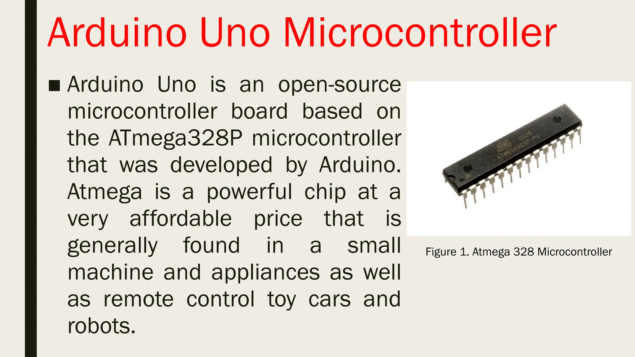
Arduino Uno Microcontroller ■Arduino Uno is an open-source microcontroller board based on the ATmega328P microcontroller that was developed by Arduino. Atmega is a powerful chip at a very affordable price that is generally found in a small machine and appliances as well as remote control toy cars and robots. Figure 1. Atmega 328 Microcontroller
13.
Arduino Uno Microcontroller ■Arduino Uno is the first in a series of USB-based boards. It is highly recommended for beginners because it is the most documented in the Arduino family and provides an easy-to-use interface.
14.
Arduino Uno Microcontroller ■IoT (Internet of Things) is a system that allows people around the world to exchange data and to connect almost “all things” like electronic and computing devices, appliances, machines, and other applications with embedded systems over the Internet. It is now one of the latest trends in the development of microcontroller projects.
15.
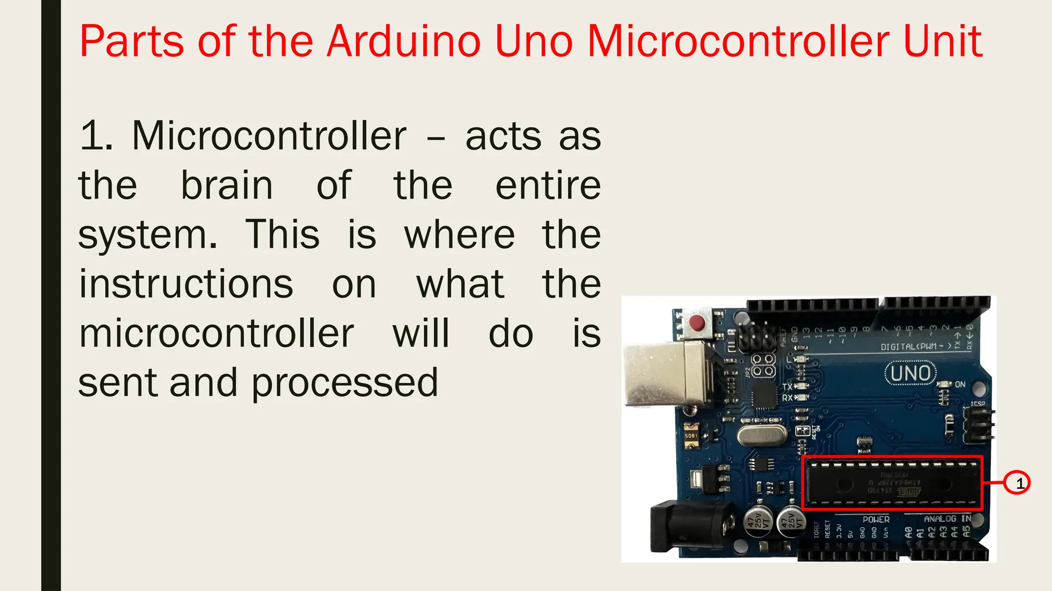
Parts of theArduino Uno Microcontroller Unit 1 1. Microcontroller – acts as the brain of the entire system. This is where the instructions on what the microcontroller will do is sent and processed
16.
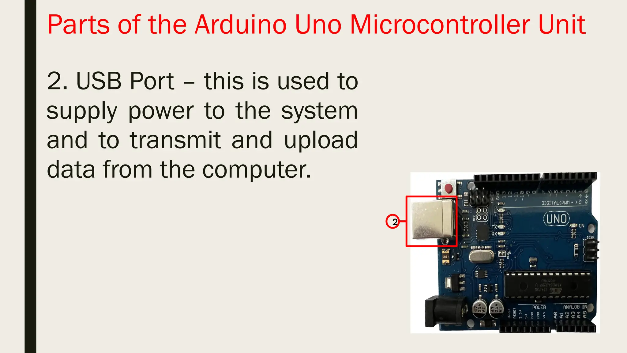
Parts of theArduino Uno Microcontroller Unit 2. USB Port – this is used to supply power to the system and to transmit and upload data from the computer. 2
17.
Parts of theArduino Uno Microcontroller Unit 2. USB Port – this is used to supply power to the system and to transmit and upload data from the computer. 2
18.
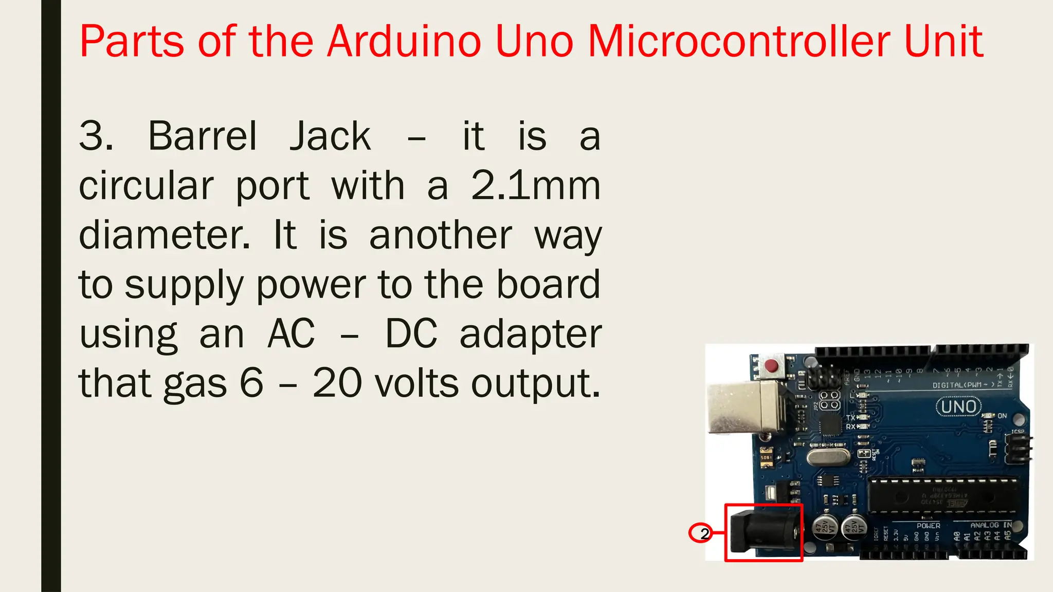
Parts of theArduino Uno Microcontroller Unit 3. Barrel Jack – it is a circular port with a 2.1mm diameter. It is another way to supply power to the board using an AC – DC adapter that gas 6 – 20 volts output. 2
19.
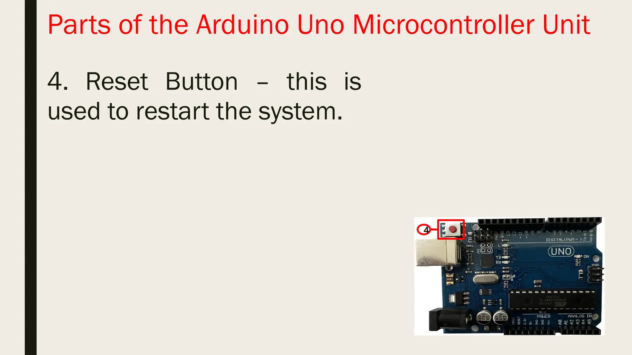
Parts of theArduino Uno Microcontroller Unit 4. Reset Button – this is used to restart the system. 4
20.
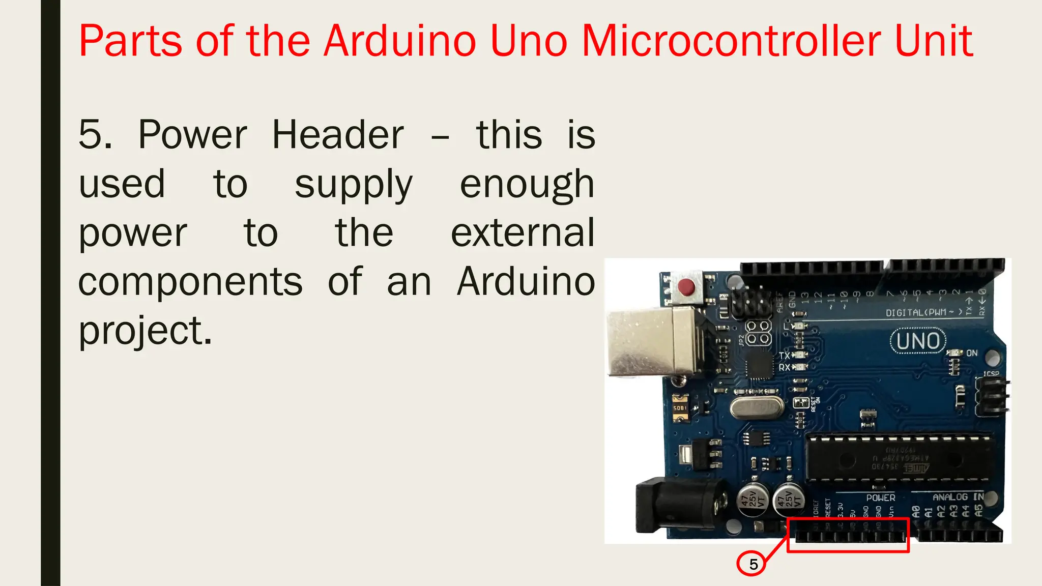
Parts of theArduino Uno Microcontroller Unit 5. Power Header – this is used to supply enough power to the external components of an Arduino project. 5
21.
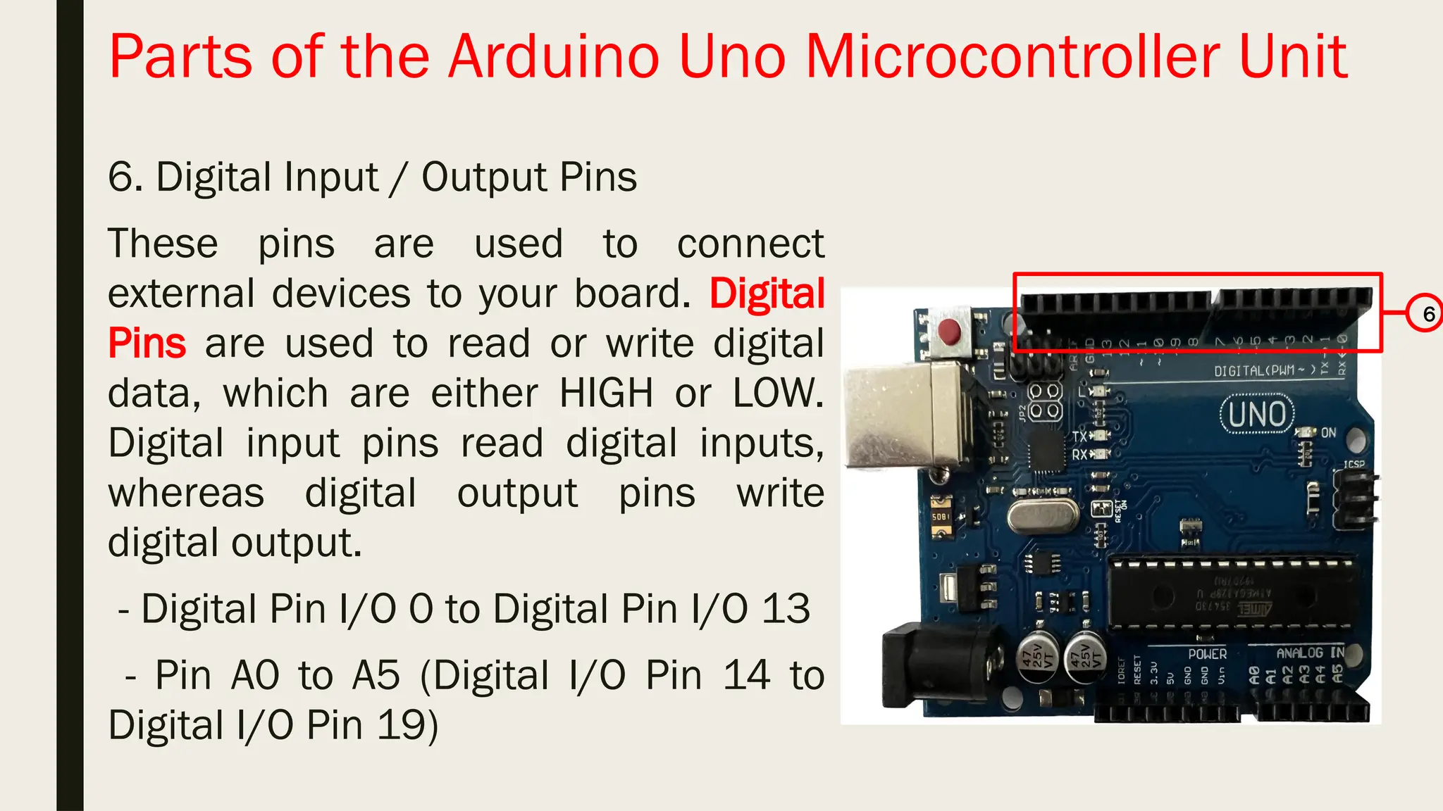
Parts of theArduino Uno Microcontroller Unit 6. Digital Input / Output Pins These pins are used to connect external devices to your board. Digital Pins are used to read or write digital data, which are either HIGH or LOW. Digital input pins read digital inputs, whereas digital output pins write digital output. - Digital Pin I/O 0 to Digital Pin I/O 13 - Pin A0 to A5 (Digital I/O Pin 14 to Digital I/O Pin 19) 6
22.
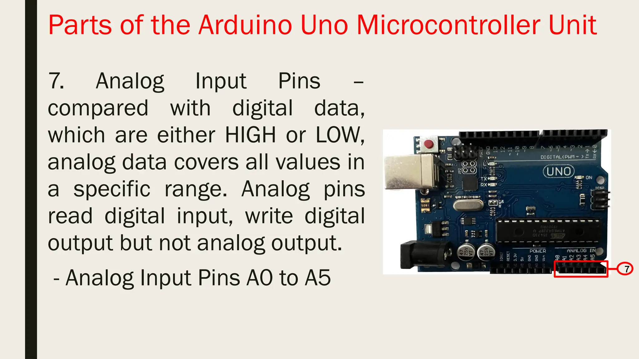
Parts of theArduino Uno Microcontroller Unit 7. Analog Input Pins – compared with digital data, which are either HIGH or LOW, analog data covers all values in a specific range. Analog pins read digital input, write digital output but not analog output. - Analog Input Pins A0 to A5 7
23.
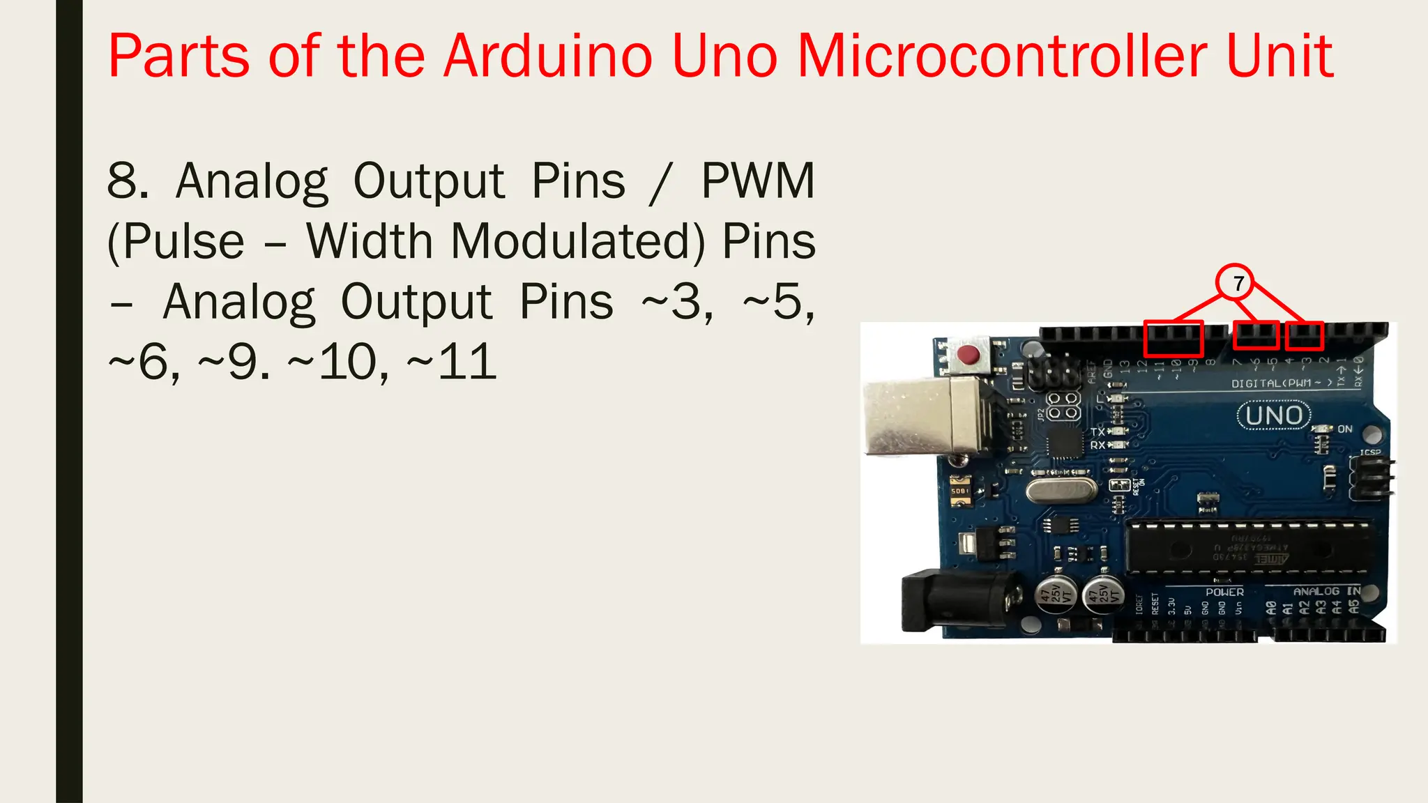
Parts of theArduino Uno Microcontroller Unit 8. Analog Output Pins / PWM (Pulse – Width Modulated) Pins – Analog Output Pins ~3, ~5, ~6, ~9. ~10, ~11 7
Integrated Development Environment(IDE) Is a software application that provides the developer or programmer a development tool with a graphic user interface (GUI) to write and test the code =. It makes it easier to write Arduino code, conduct testing, and upload data to the microcontroller. It was designed using the Java Programming Language and was based on Processing Language together with other open-source software.
26.
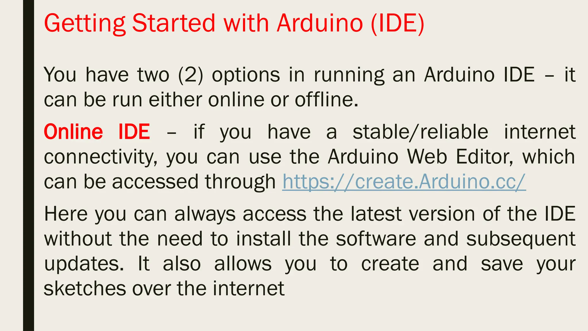
Getting Started withArduino (IDE) You have two (2) options in running an Arduino IDE – it can be run either online or offline. Online IDE – if you have a stable/reliable internet connectivity, you can use the Arduino Web Editor, which can be accessed through https://create.Arduino.cc/ Here you can always access the latest version of the IDE without the need to install the software and subsequent updates. It also allows you to create and save your sketches over the internet
27.
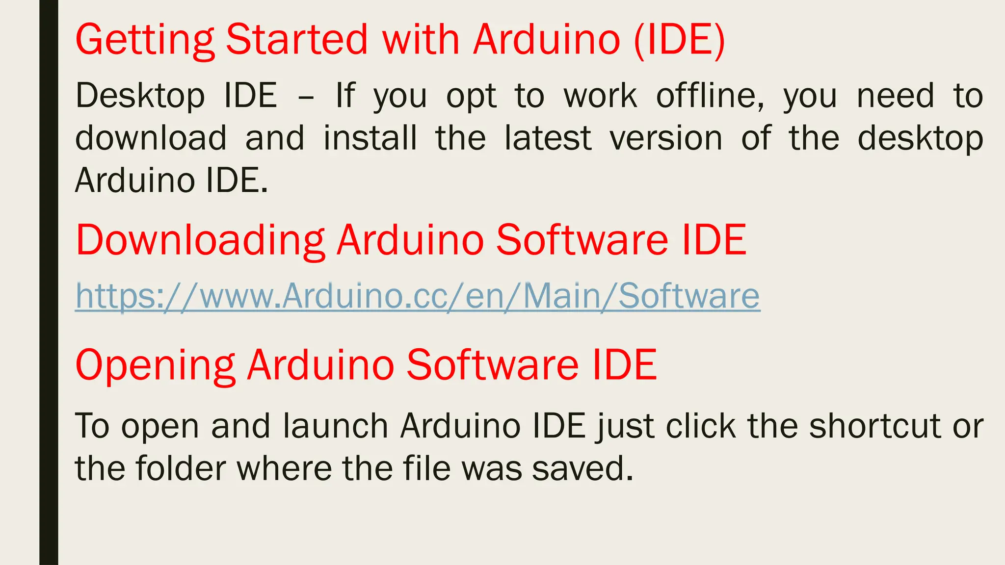
Getting Started withArduino (IDE) Desktop IDE – If you opt to work offline, you need to download and install the latest version of the desktop Arduino IDE. Downloading Arduino Software IDE https://www.Arduino.cc/en/Main/Software Opening Arduino Software IDE To open and launch Arduino IDE just click the shortcut or the folder where the file was saved.
28.
Installing Arduino IDE Afterthe Arduino IDE software has been downloaded, simply double-click the file that was saved. Follow the on-screen instructions and finish the installation.
30.
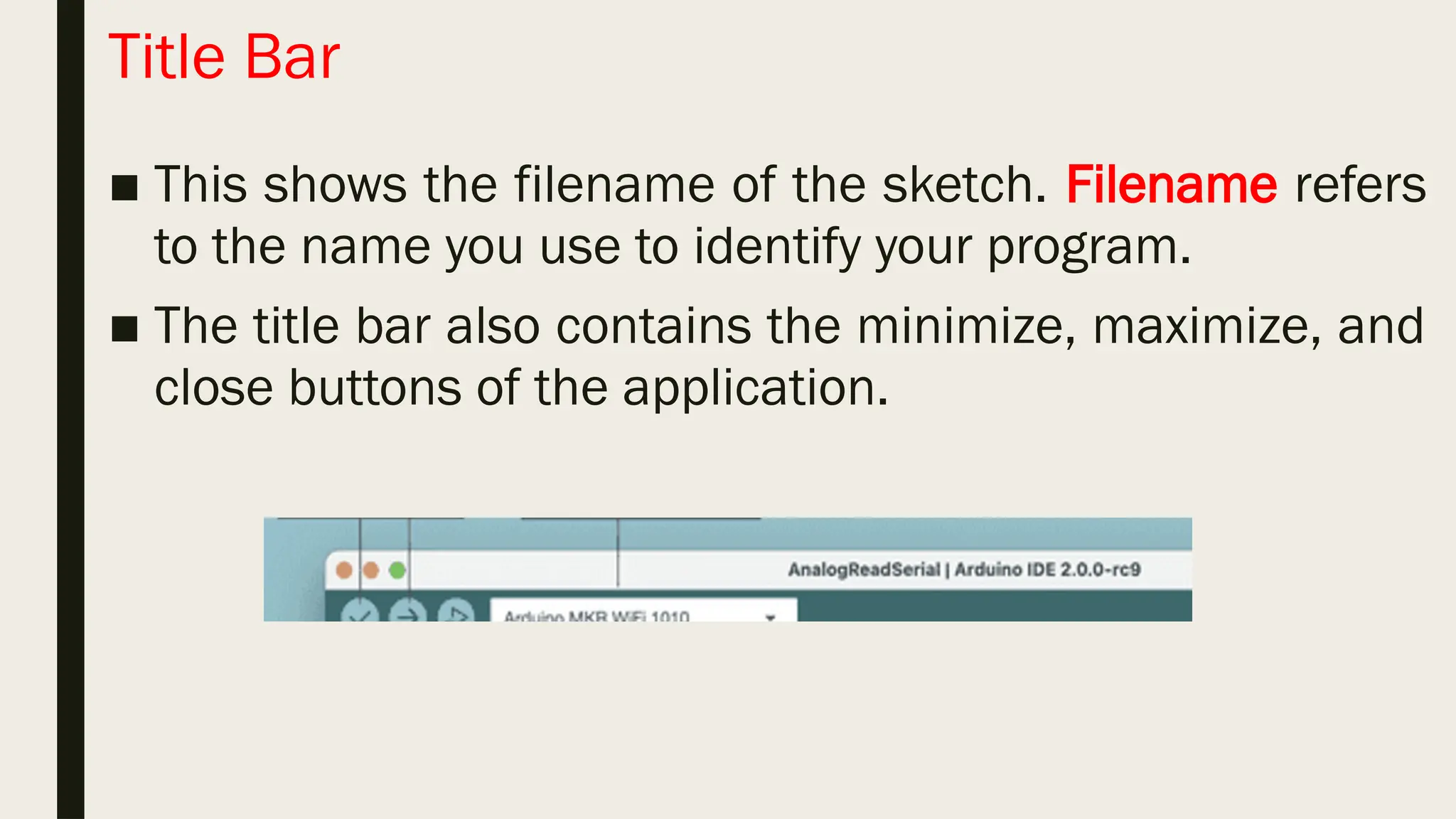
Title Bar ■ Thisshows the filename of the sketch. Filename refers to the name you use to identify your program. ■ The title bar also contains the minimize, maximize, and close buttons of the application.
31.
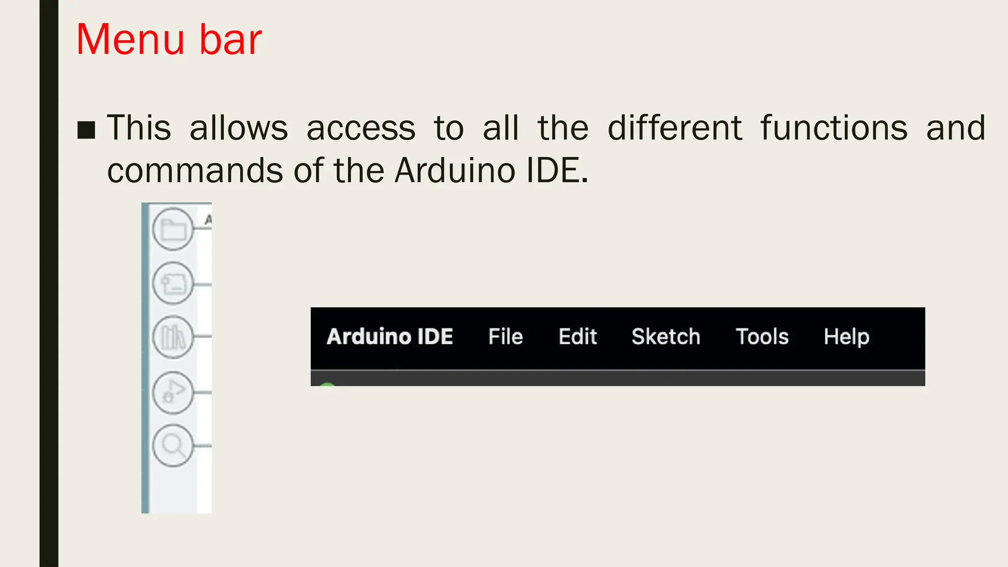
Menu bar ■ Thisallows access to all the different functions and commands of the Arduino IDE.
32.
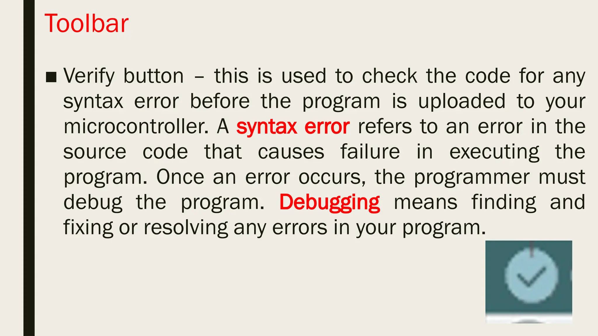
Toolbar ■ Verify button– this is used to check the code for any syntax error before the program is uploaded to your microcontroller. A syntax error refers to an error in the source code that causes failure in executing the program. Once an error occurs, the programmer must debug the program. Debugging means finding and fixing or resolving any errors in your program.
33.
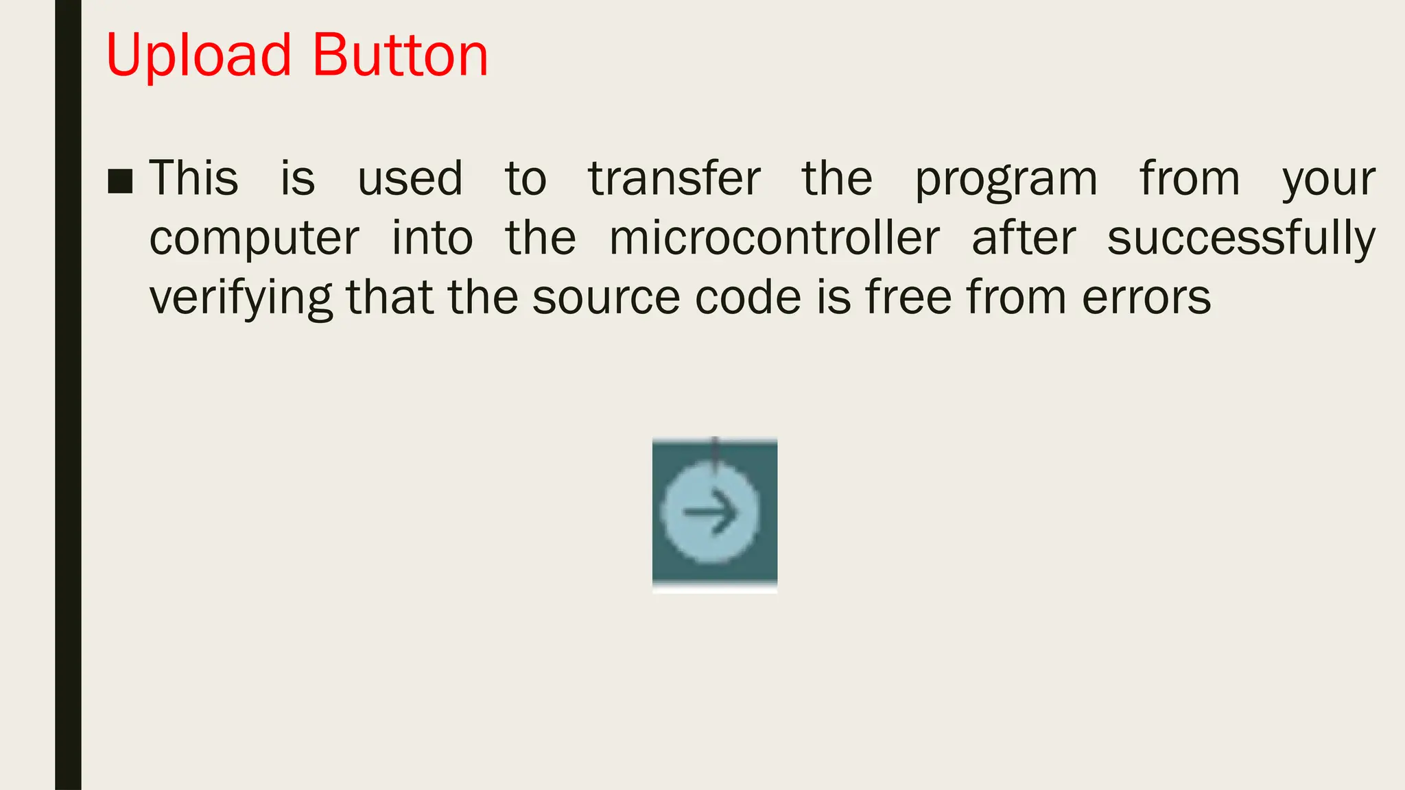
Upload Button ■ Thisis used to transfer the program from your computer into the microcontroller after successfully verifying that the source code is free from errors
34.
New File Button ■This allows you to create a new file or new Arduino window. Open button ■ This is used to retrieve previous sketch/sketches. Save button ■ This allows you to save the current sketch to your computer.
35.
Serial Monitor ■ Thisconnects the computer and the Arduino and is used to send and receive serial data. It is also useful for debugging purposes and can be used to control the Arduino using the keyboard. Status Bar ■ This provides feedback after the verification and compiling of the program.
Hardware ■ The physicalpart or component of a machine. ■ These are tangible components that you can touch, see, and feel. ■ Users cannot duplicate the hardware unless it is constructed or manufactured using physical materials and or components. ■ It can be replaced with a new one if damaged. ■ It is not affected by computer viruses. ■ It cannot be electronically transferred through a computer network.
38.
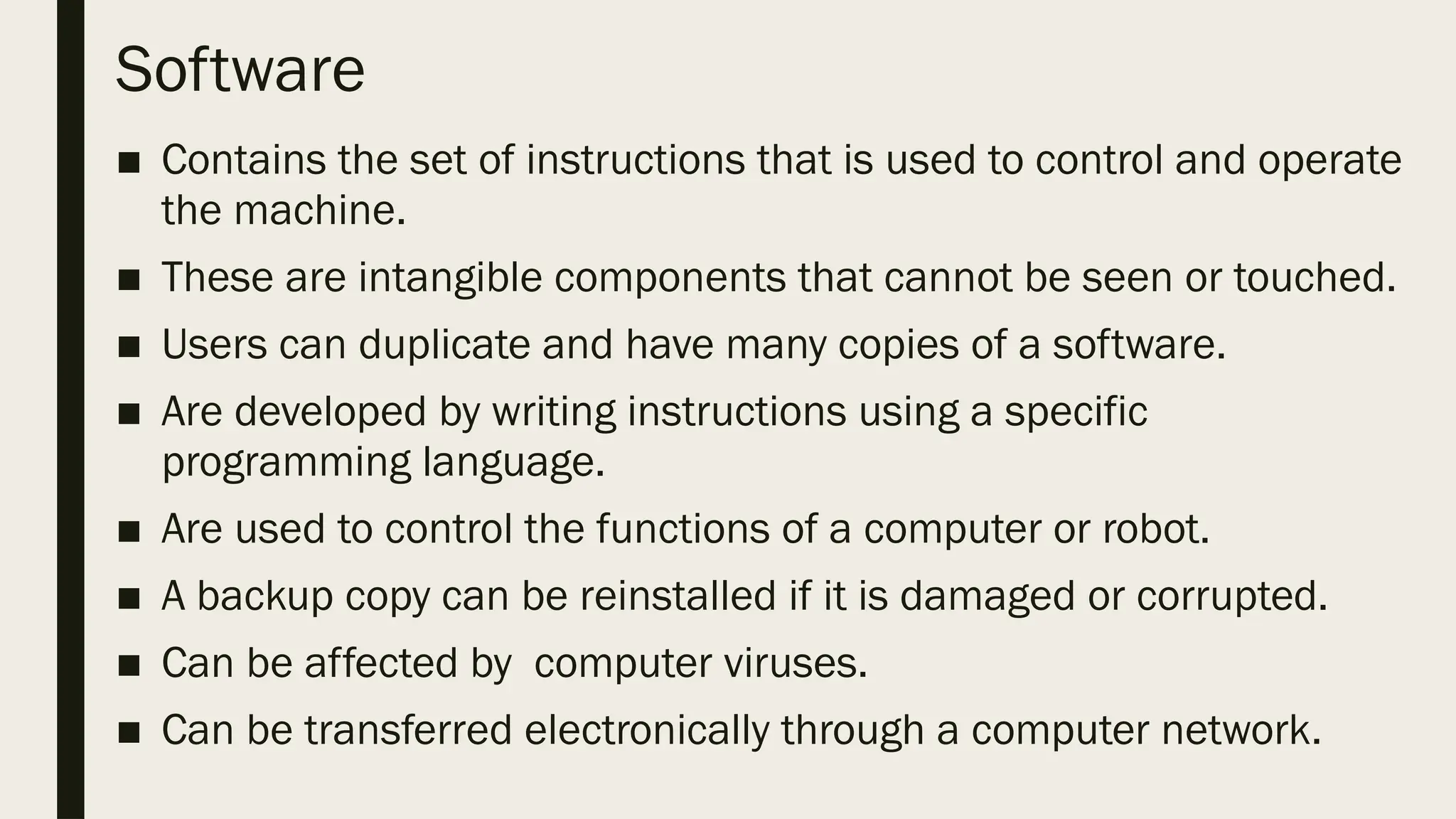
Software ■ Contains theset of instructions that is used to control and operate the machine. ■ These are intangible components that cannot be seen or touched. ■ Users can duplicate and have many copies of a software. ■ Are developed by writing instructions using a specific programming language. ■ Are used to control the functions of a computer or robot. ■ A backup copy can be reinstalled if it is damaged or corrupted. ■ Can be affected by computer viruses. ■ Can be transferred electronically through a computer network.
39.
Program and ProgrammingLanguage ■ A software program is a set of instructions that is used to tell a machine what to do. There are various ways to write these commands using different types of programming languages. A programming language is used by programmers and developers to write code that contain commands that will be executed by a computer device. The Arduino microcontroller can be developed using different programming languages like the MATLAB, Industrial Robot Languages, C/C++, C#/.Net, Java, Python, and more.
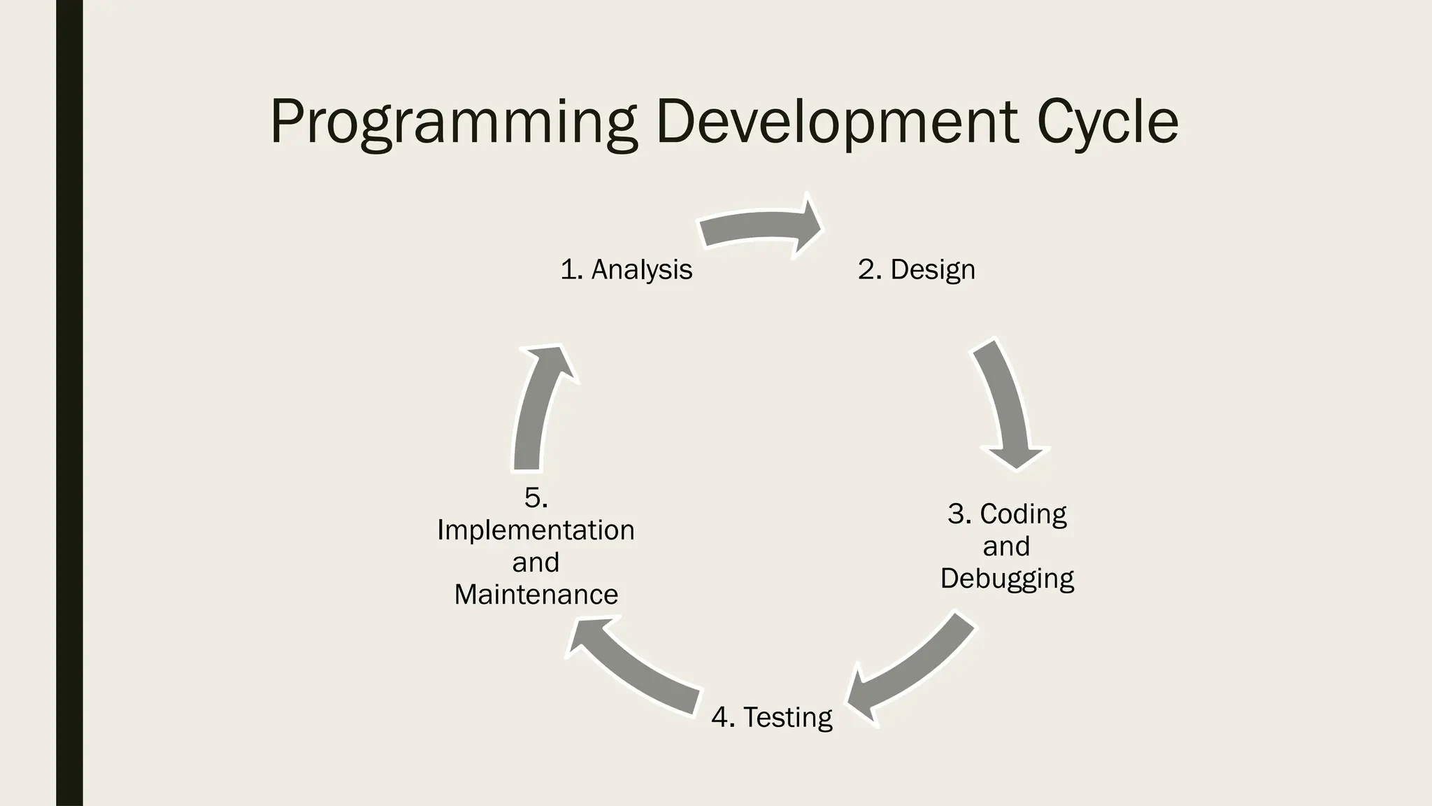
1. Analysis ■ Thisphase defines and analyzes the problem. The success of a computer program may depend on the proper analysis of what you want a program to do. This is made possible by identifying the purpose of the program, the problems to be solved, the requirements, and the possible solutions.
42.
2. Design ■ Inthis phase, the programmer designs an algorithm of the solutions to the problem before writing the actual program. An algorithm is a sequence of instructions needed to solve the problem. The programmer may also use a visual representation of the solution to the problem using a flowchart.
43.
3. Coding andDebugging ■ This phase refers to the process of writing code or instructions using a specific programming language. After writing the code, the programmer must detect, locate, and correct any syntax errors. This process is known as debugging. Syntax refers to the grammatical rules of a specific programming language.
44.
4. Testing ■ Oncethe program is free from any errors or bugs, the programmer needs to check the program’s efficiency to ensure that there are no logical errors. This means it works as it is expected and meets the requirements based on the specifications that were analyzed.
45.
5. Implementation andMaintenance ■ Implementation means the program is ready for use after it has passed all the previous phases and met the specified requirements. During implementation, the program may require upgrading and maintenance to adapt to minor changes in the requirements.
46.
Algorithms, Pseudocode, andFlowcharts ■ Algorithms, pseudocode, and flowcharts are common tools used in designing the solution to a problem. These are helpful in developing a program especially for beginners. Since they are independent of a specific programming language, they make it easier to understand the problem and its requirements, and to study possible alternative solutions before writing the actual program.
47.
Advantages ■ They areprogram – independent. This means that they can be learned without a formal background in any programming language. ■ They offer substitutes to the usual lengthy narrative description of program. ■ They are easier to understand than a program written in a specific programming language. ■ They allow the users the chance to focus on other important matters. ■ They allow easy analysis in each part of the process in the program.
48.
Limitations ■ Since itis program independent, it does not represent any programming language. This means that it is understandable by person-to-person rather that person- to-computer. ■ They do not represent a natural means of communication. ■ They only show the step-by-step process in the program, but do not explain why a particular set of operation is made.
49.
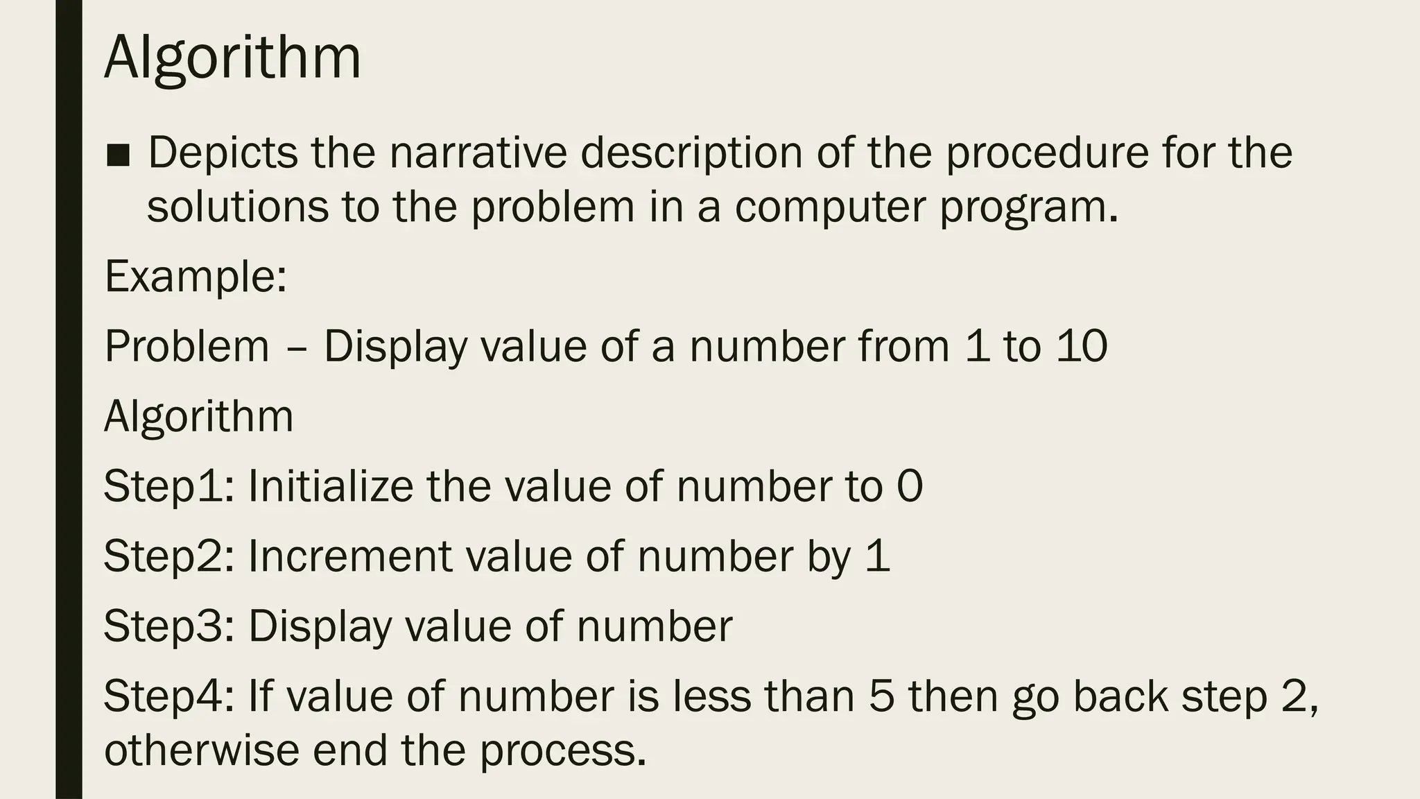
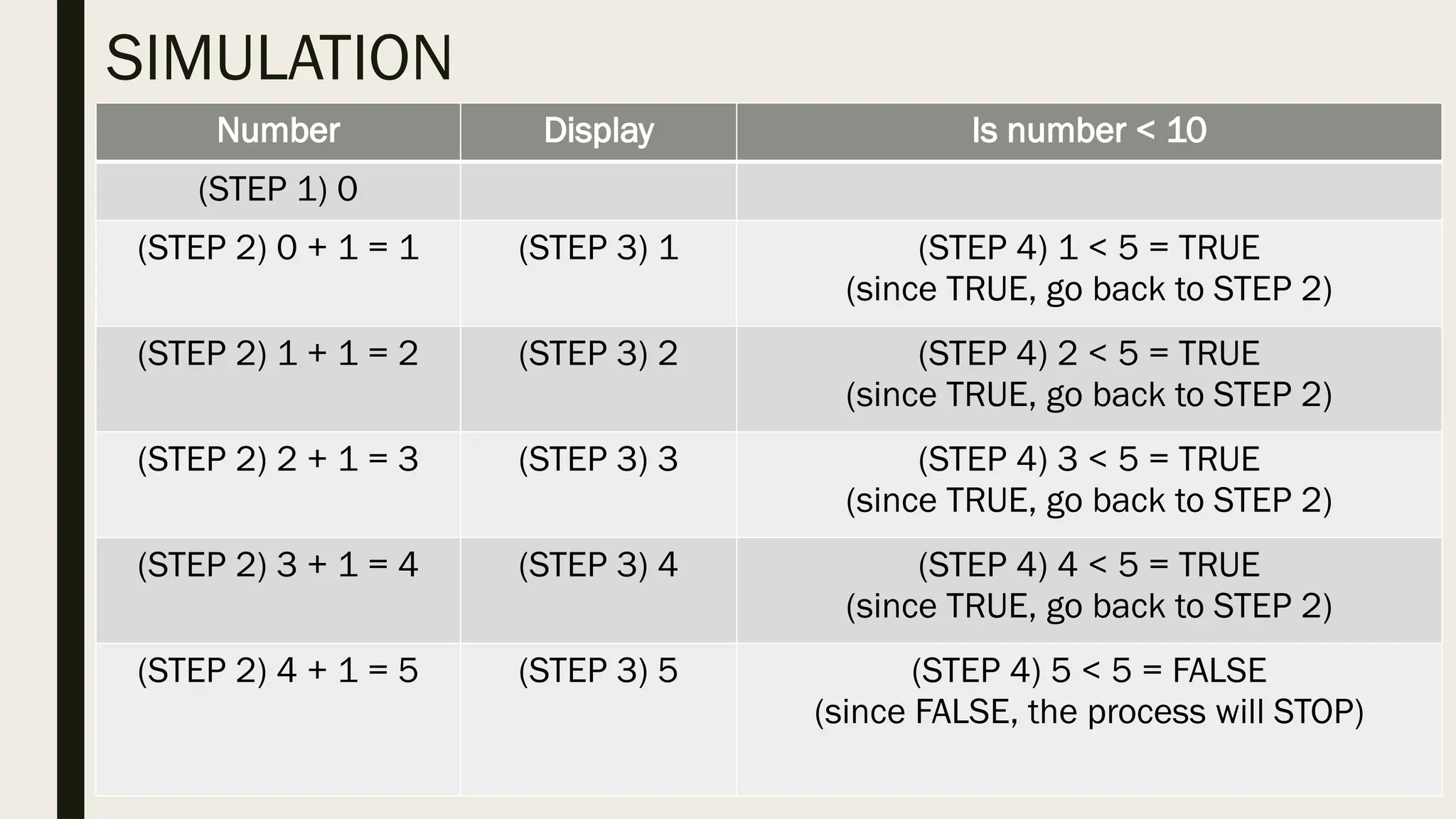
Algorithm ■ Depicts thenarrative description of the procedure for the solutions to the problem in a computer program. Example: Problem – Display value of a number from 1 to 10 Algorithm Step1: Initialize the value of number to 0 Step2: Increment value of number by 1 Step3: Display value of number Step4: If value of number is less than 5 then go back step 2, otherwise end the process.
50.
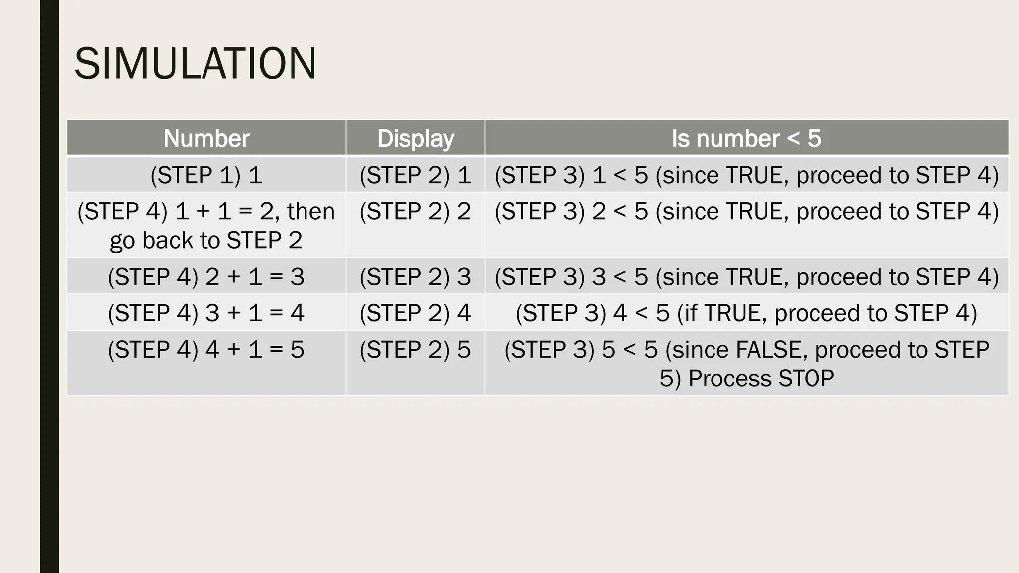
Number Display Isnumber < 10 (STEP 1) 0 (STEP 2) 0 + 1 = 1 (STEP 3) 1 (STEP 4) 1 < 5 = TRUE (since TRUE, go back to STEP 2) (STEP 2) 1 + 1 = 2 (STEP 3) 2 (STEP 4) 2 < 5 = TRUE (since TRUE, go back to STEP 2) (STEP 2) 2 + 1 = 3 (STEP 3) 3 (STEP 4) 3 < 5 = TRUE (since TRUE, go back to STEP 2) (STEP 2) 3 + 1 = 4 (STEP 3) 4 (STEP 4) 4 < 5 = TRUE (since TRUE, go back to STEP 2) (STEP 2) 4 + 1 = 5 (STEP 3) 5 (STEP 4) 5 < 5 = FALSE (since FALSE, the process will STOP) SIMULATION
51.
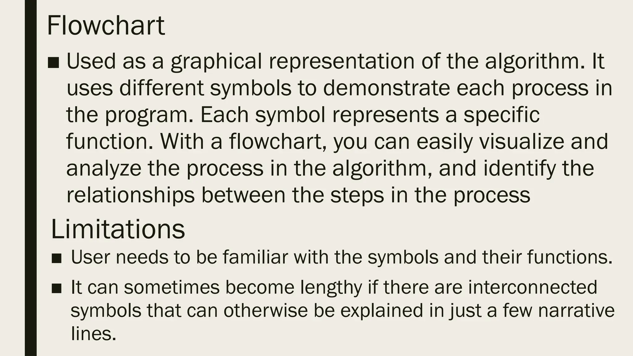
Flowchart ■ Used asa graphical representation of the algorithm. It uses different symbols to demonstrate each process in the program. Each symbol represents a specific function. With a flowchart, you can easily visualize and analyze the process in the algorithm, and identify the relationships between the steps in the process Limitations ■ User needs to be familiar with the symbols and their functions. ■ It can sometimes become lengthy if there are interconnected symbols that can otherwise be explained in just a few narrative lines.
52.
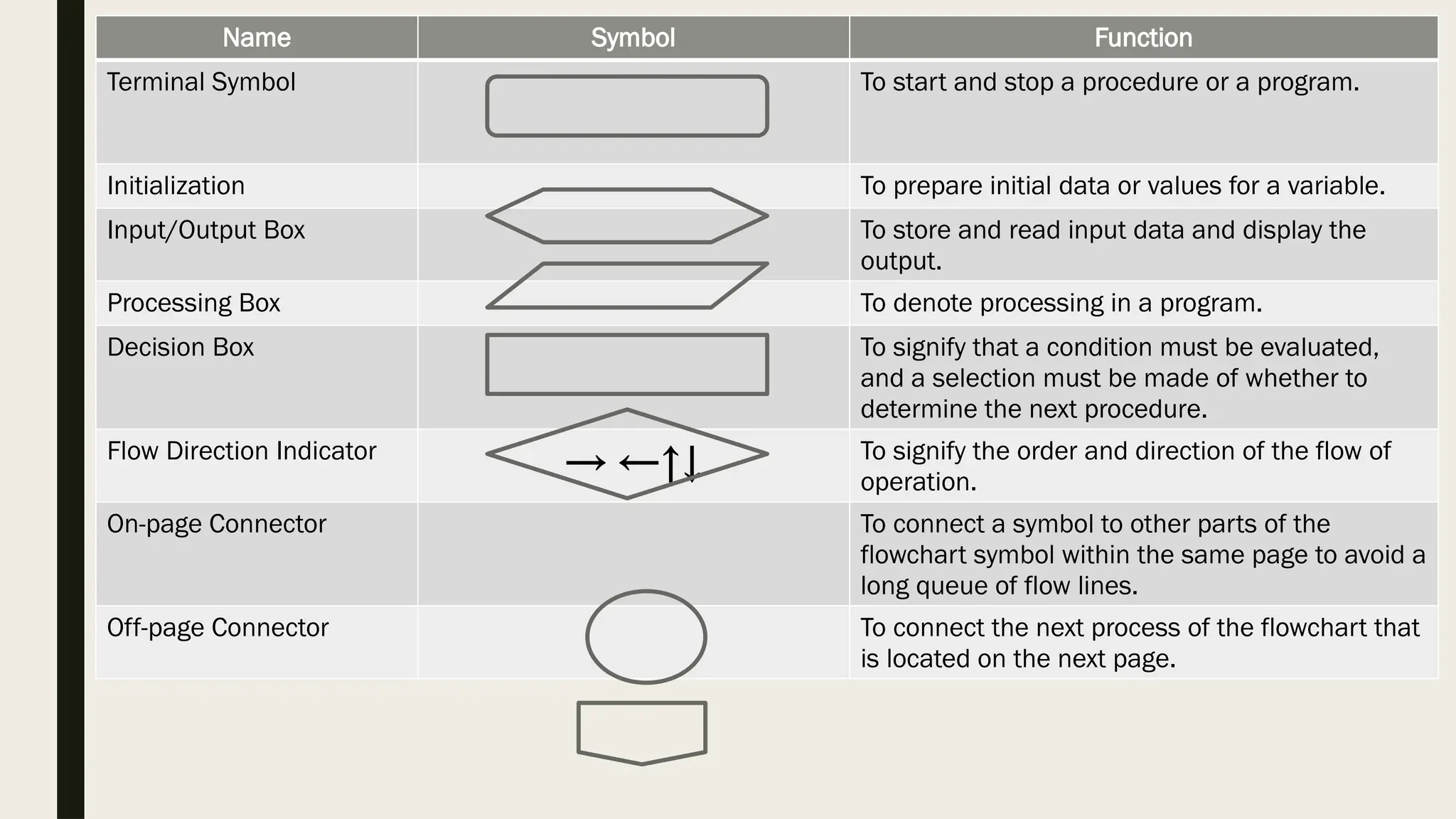
Name Symbol Function TerminalSymbol To start and stop a procedure or a program. Initialization To prepare initial data or values for a variable. Input/Output Box To store and read input data and display the output. Processing Box To denote processing in a program. Decision Box To signify that a condition must be evaluated, and a selection must be made of whether to determine the next procedure. Flow Direction Indicator → ←↑↓ To signify the order and direction of the flow of operation. On-page Connector To connect a symbol to other parts of the flowchart symbol within the same page to avoid a long queue of flow lines. Off-page Connector To connect the next process of the flowchart that is located on the next page.
53.
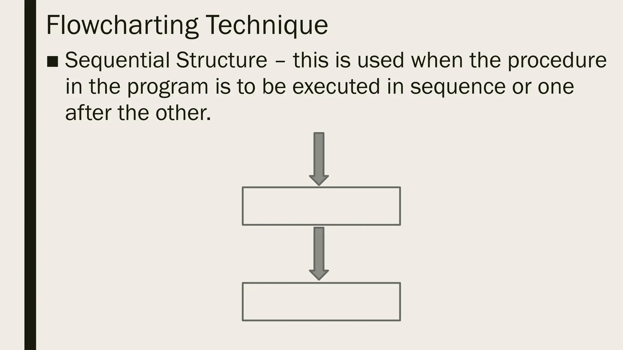
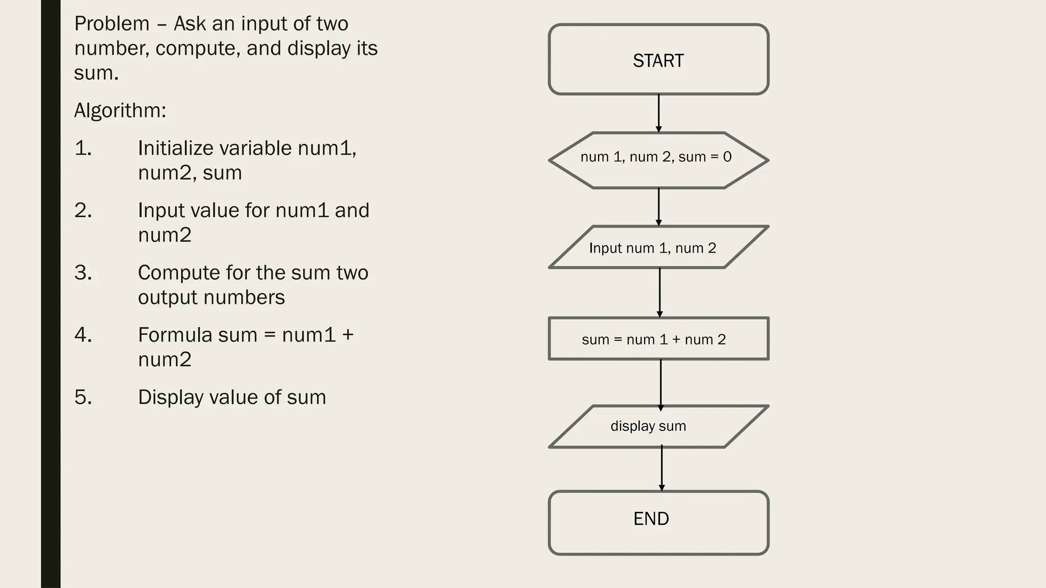
Flowcharting Technique ■ SequentialStructure – this is used when the procedure in the program is to be executed in sequence or one after the other.
54.
Problem – Askan input of two number, compute, and display its sum. Algorithm: 1. Initialize variable num1, num2, sum 2. Input value for num1 and num2 3. Compute for the sum two output numbers 4. Formula sum = num1 + num2 5. Display value of sum START num 1, num 2, sum = 0 Input num 1, num 2 sum = num 1 + num 2 display sum END
55.
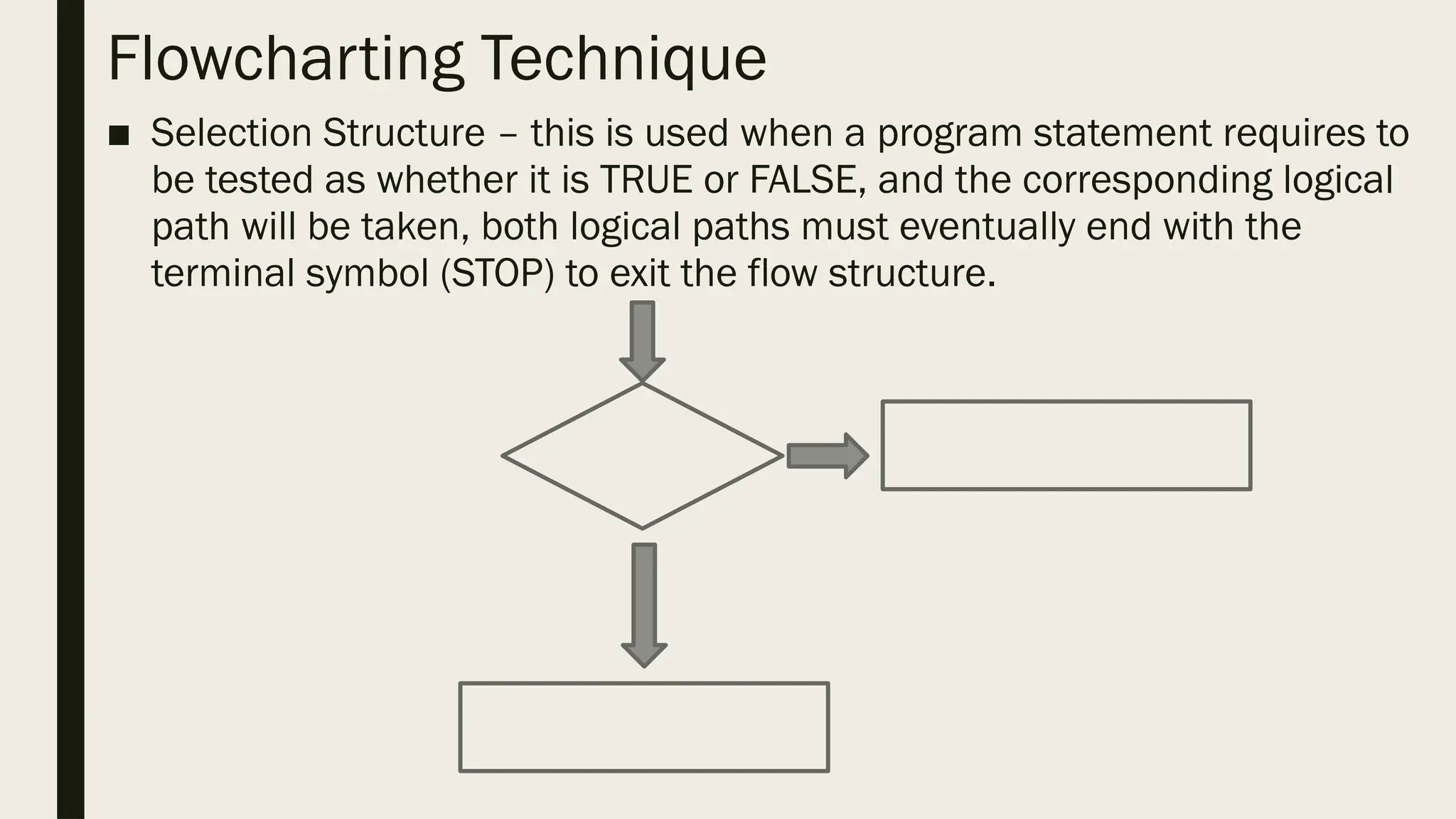
Flowcharting Technique ■ SelectionStructure – this is used when a program statement requires to be tested as whether it is TRUE or FALSE, and the corresponding logical path will be taken, both logical paths must eventually end with the terminal symbol (STOP) to exit the flow structure.
56.
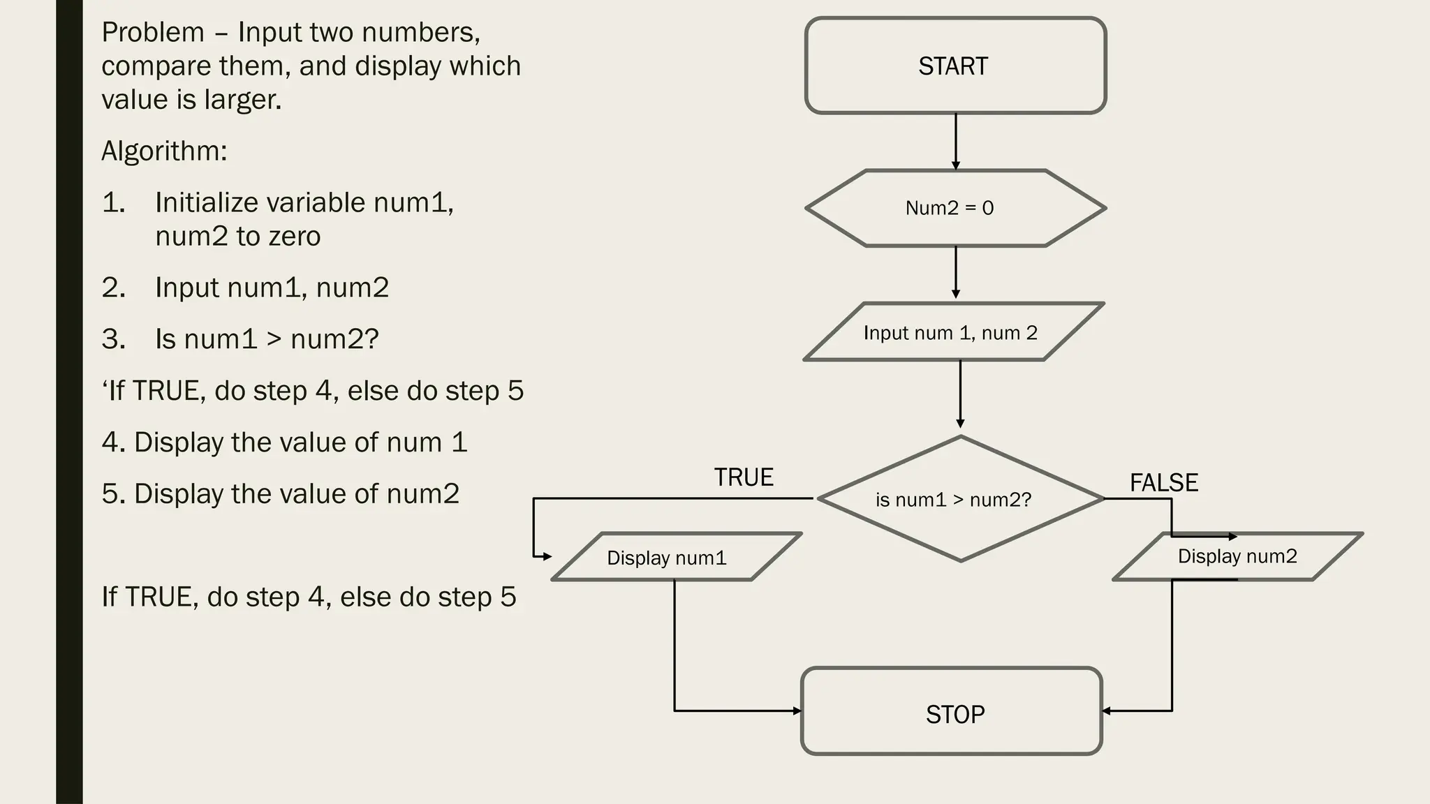
Problem – Inputtwo numbers, compare them, and display which value is larger. Algorithm: 1. Initialize variable num1, num2 to zero 2. Input num1, num2 3. Is num1 > num2? ‘If TRUE, do step 4, else do step 5 4. Display the value of num 1 5. Display the value of num2 If TRUE, do step 4, else do step 5 START Num2 = 0 Input num 1, num 2 STOP is num1 > num2? Display num1 Display num2 TRUE FALSE
57.
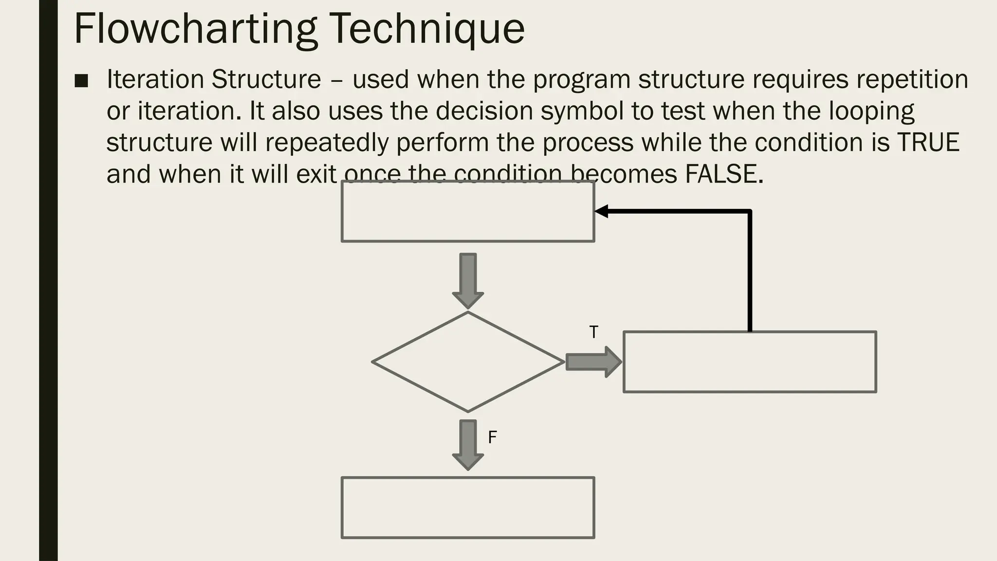
Flowcharting Technique ■ IterationStructure – used when the program structure requires repetition or iteration. It also uses the decision symbol to test when the looping structure will repeatedly perform the process while the condition is TRUE and when it will exit once the condition becomes FALSE. T F
58.
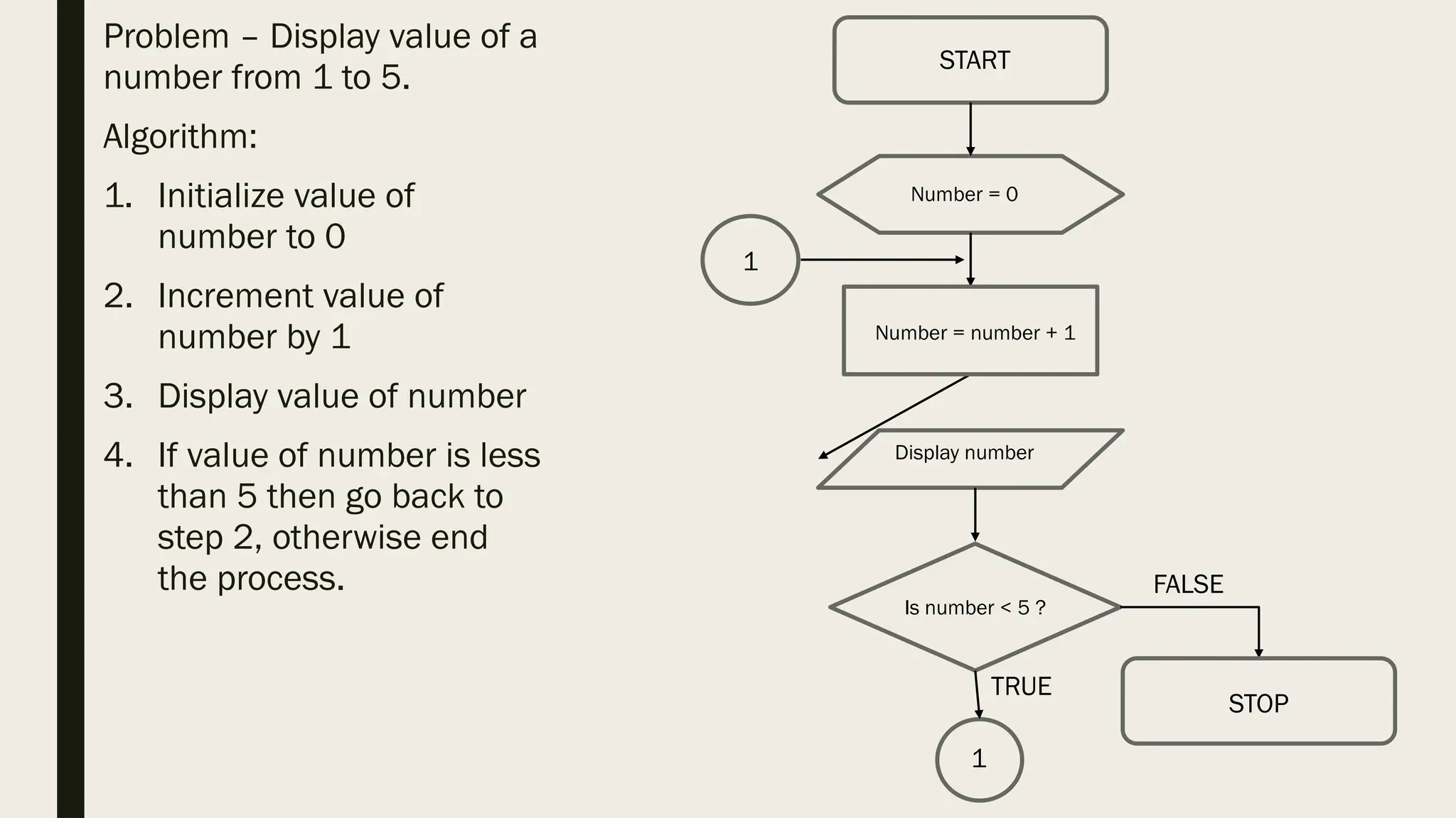
Problem – Displayvalue of a number from 1 to 5. Algorithm: 1. Initialize value of number to 0 2. Increment value of number by 1 3. Display value of number 4. If value of number is less than 5 then go back to step 2, otherwise end the process. START Number = 0 Number = number + 1 STOP Is number < 5 ? Display number FALSE 1 1 TRUE
59.
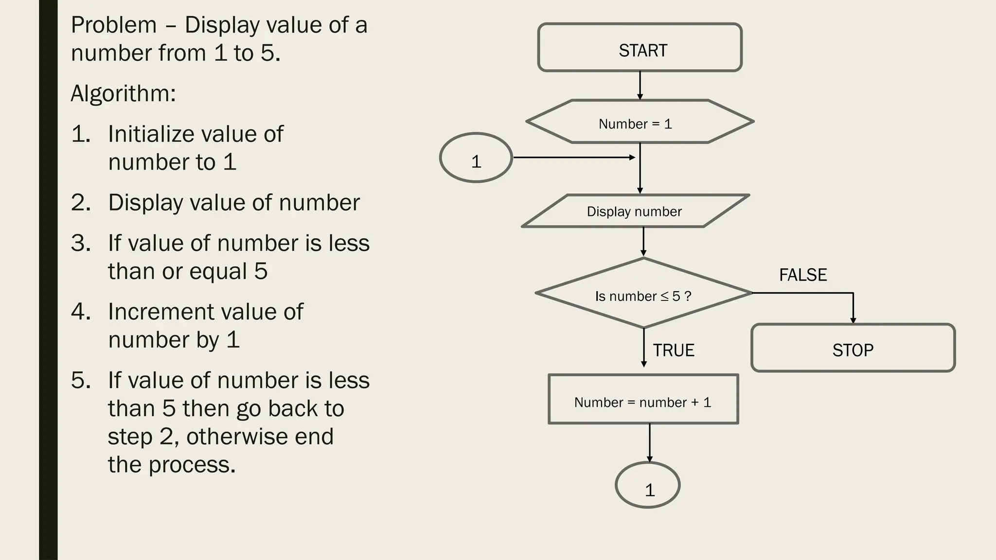
Problem – Displayvalue of a number from 1 to 5. Algorithm: 1. Initialize value of number to 1 2. Display value of number 3. If value of number is less than or equal 5 4. Increment value of number by 1 5. If value of number is less than 5 then go back to step 2, otherwise end the process. STOP START Number = 1 Is number ≤ 5 ? Display number FALSE 1 1 TRUE Number = number + 1
Pseudocode ■ An algorithmthat uses English structured phrases to represent the process to be processed in a program. Its difference with the usual algorithm is that it resembles the statement in a particular programming language. ■ It is used during the design phase to give more attention to the logic of the algorithm without being distracted by the programming syntax. ■ With this, it will be easier for the programmer to translate the pseudocode into a source code, a line of code written in a specific programming language that is executable and understandable by a computer.
62.
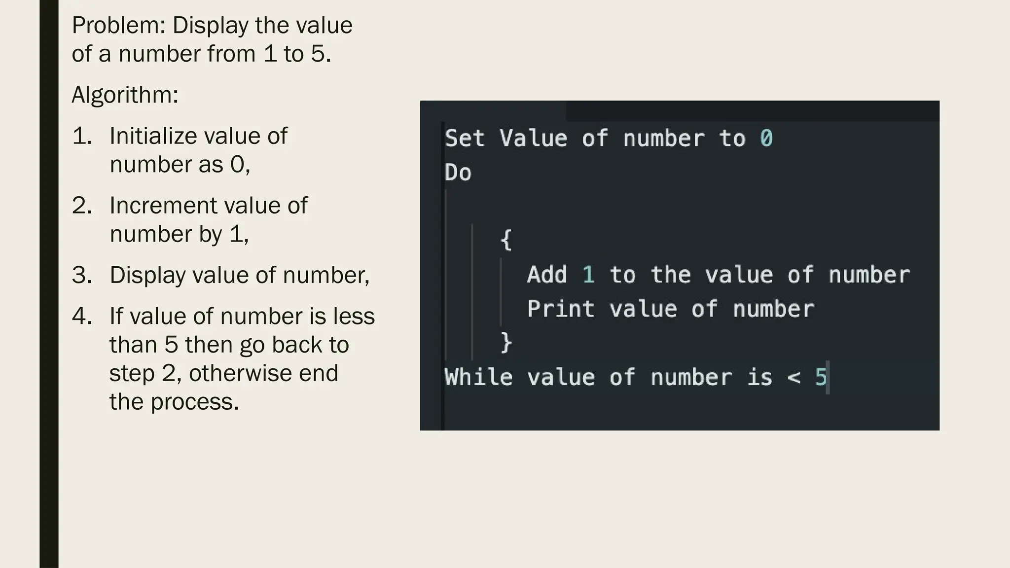
Problem: Display thevalue of a number from 1 to 5. Algorithm: 1. Initialize value of number as 0, 2. Increment value of number by 1, 3. Display value of number, 4. If value of number is less than 5 then go back to step 2, otherwise end the process.