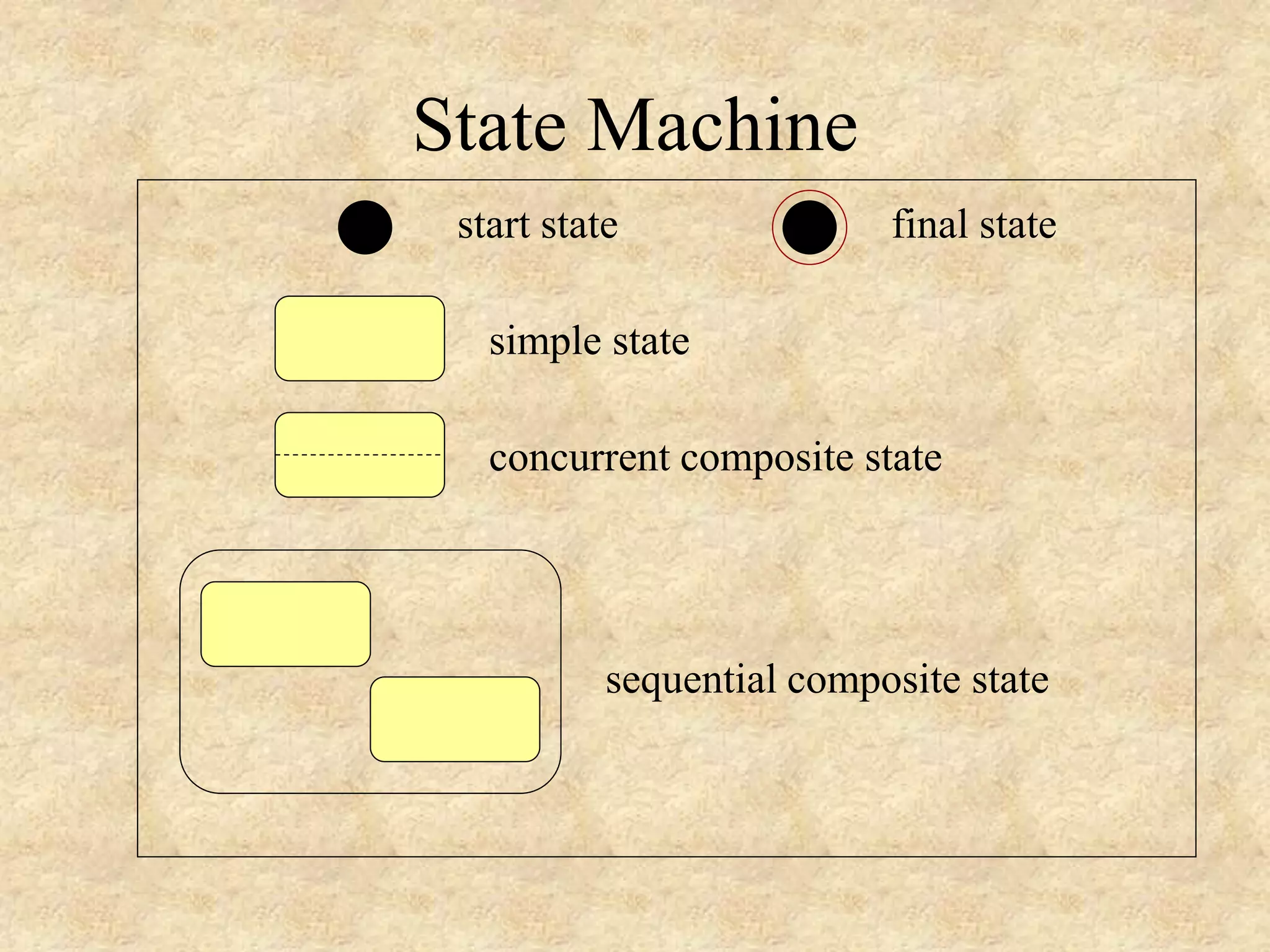
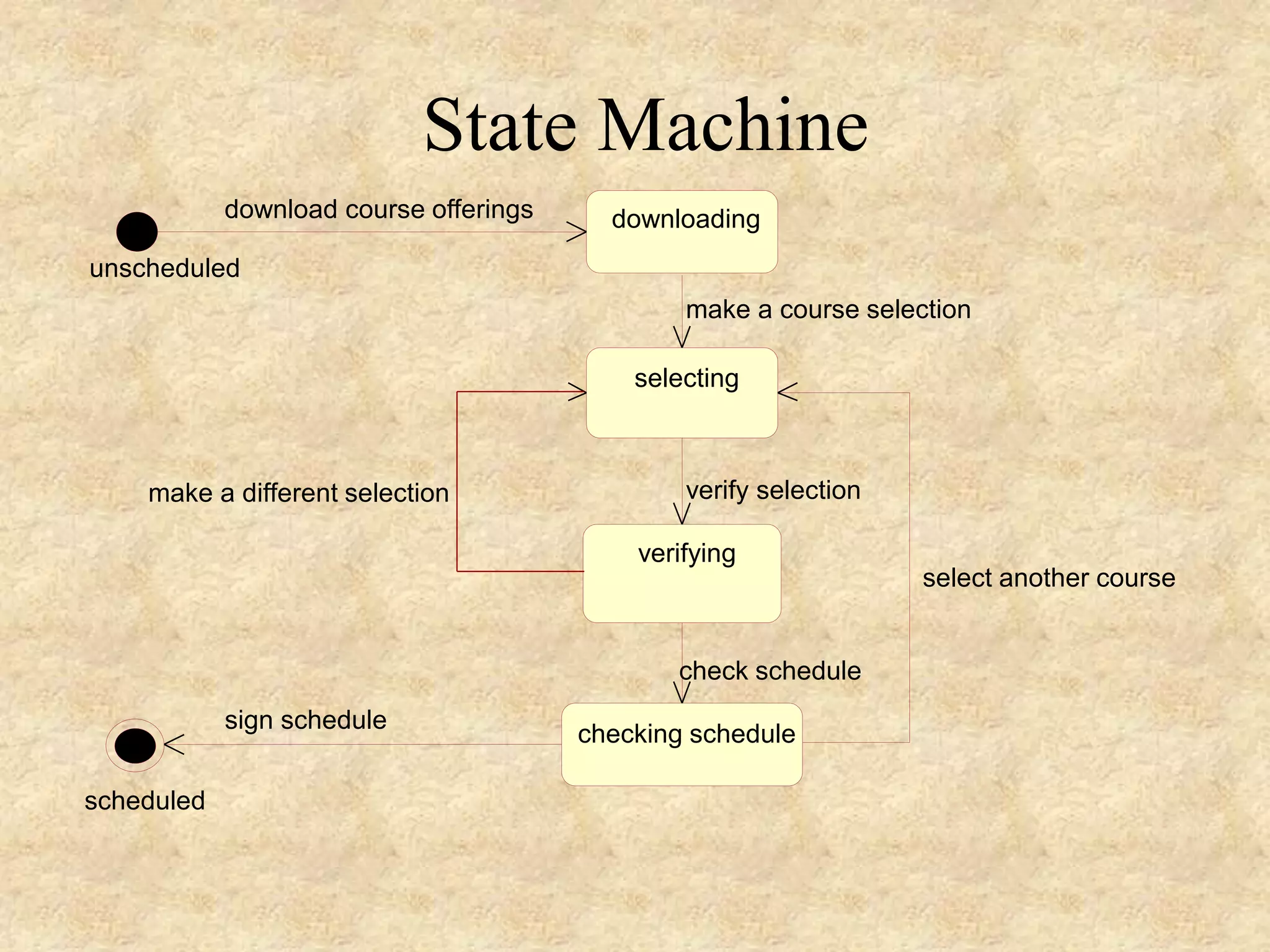
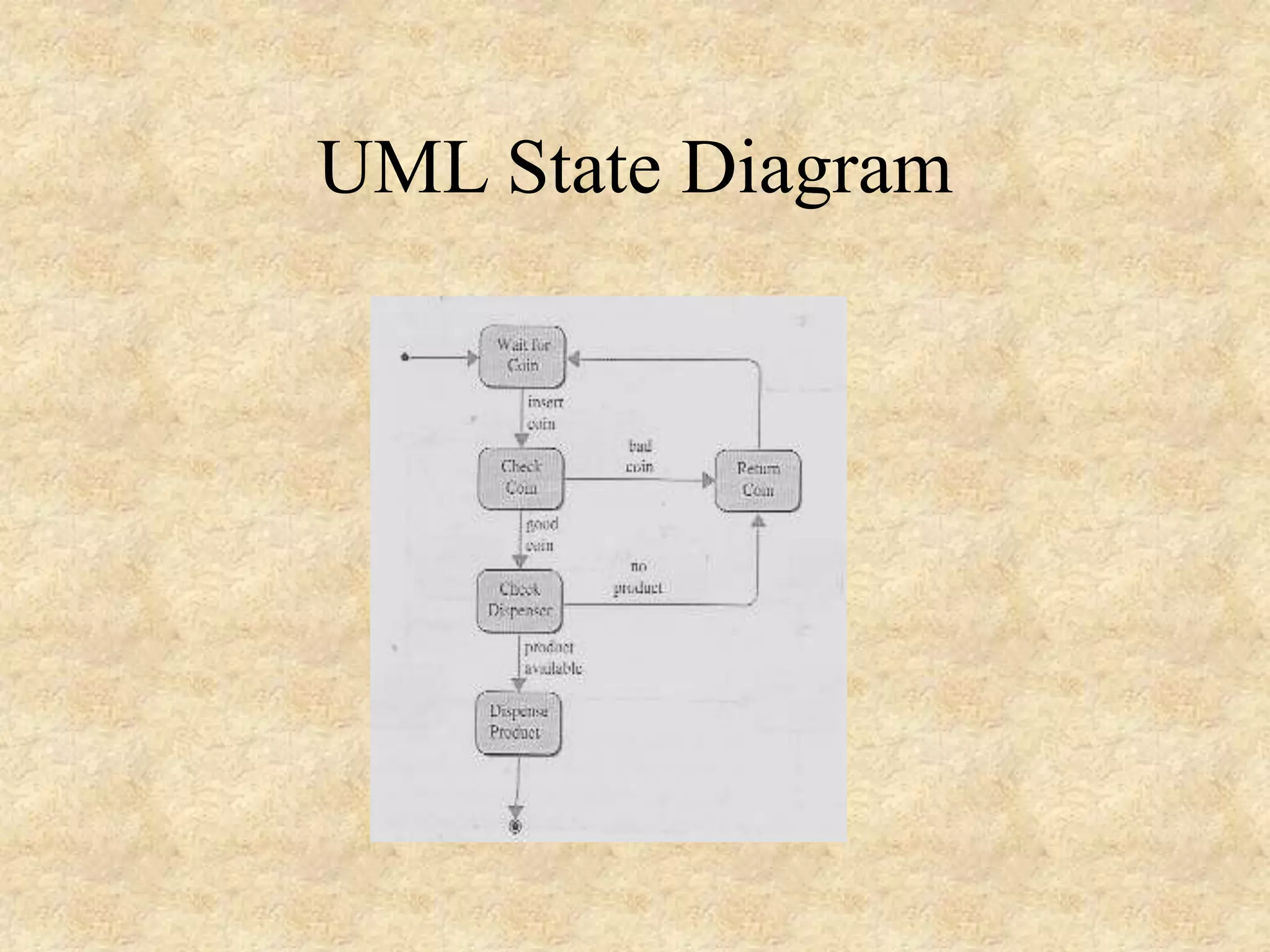
The document discusses Unified Modeling Language (UML) diagrams, including state diagrams, sequence diagrams, and collaboration diagrams. It provides details on how to construct and interpret each type of diagram. State diagrams depict object states and transitions between states. Sequence diagrams show the messages passed between objects over time. Collaboration diagrams emphasize object relationships and indicate message sequences with numbers. Both sequence and collaboration diagrams can model the same interactions between objects.
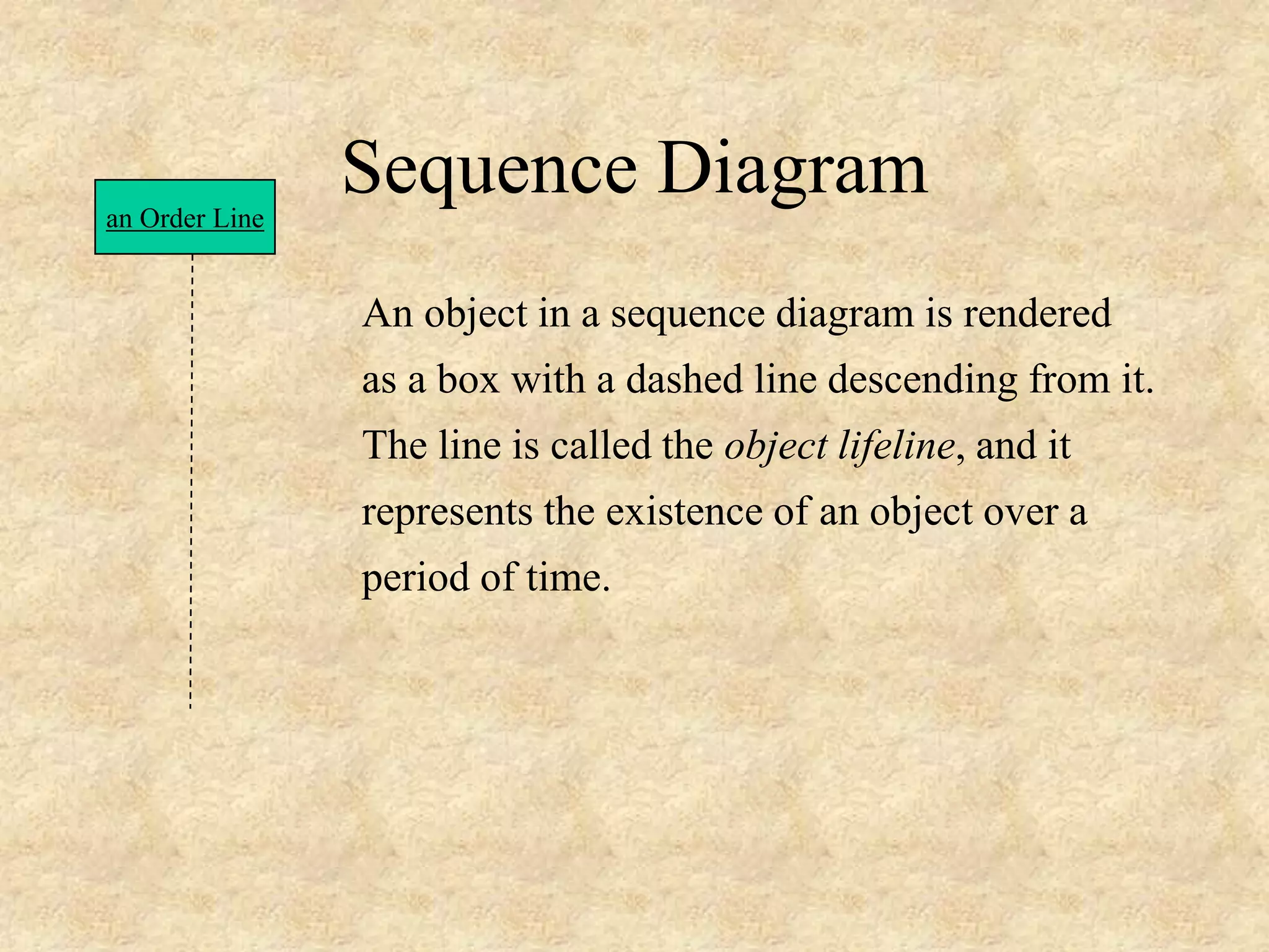
![Sequence Diagram A sequence diagram is an interaction diagram that emphasizes the time ordering of messages. It shows a set of objects and the messages sent and received by those objects. Graphically, a sequence diagram is a table that shows objects arranged along the X axis and messages, ordered in increasing time, along the Y axis. - The UML User Guide, [Booch,99]](https://image.slidesharecdn.com/lec-7-uml-200214105447/75/Software-Engineering-Lec-7-uml-11-2048.jpg)
![Sequence Diagram an Order Line a Stock Item [check = “true”] remove() check() Messages are rendered as horizontal arrows being passed from object to object as time advances down the object lifelines. Conditions ( such as [check = “true”] ) indicate when a message gets passed.](https://image.slidesharecdn.com/lec-7-uml-200214105447/75/Software-Engineering-Lec-7-uml-13-2048.jpg)
![Sequence Diagram an Order Line a Stock Item [check = “true”] remove() check() Notice that the bottom arrow is different. The arrow head is not solid, and there is no accompanying message. This arrow indicates a return from a previous message, not a new message.](https://image.slidesharecdn.com/lec-7-uml-200214105447/75/Software-Engineering-Lec-7-uml-14-2048.jpg)
![Sequence Diagram an Order a Order Line * prepare() An iteration marker, such as * (as shown), or *[i = 1..n] , indicates that a message will be repeated as indicated.Iteration marker](https://image.slidesharecdn.com/lec-7-uml-200214105447/75/Software-Engineering-Lec-7-uml-15-2048.jpg)
![an Order Entry window an Order an Order Line a Stock Item A Reorder Item A Delivery Item new [check = “true”] new [needsToReorder = “true”] needsToReorder() [check = “true”] remove() check() * prepare() prepare() Object Message Iteration Return Creation Condition Self-Delegation](https://image.slidesharecdn.com/lec-7-uml-200214105447/75/Software-Engineering-Lec-7-uml-16-2048.jpg)
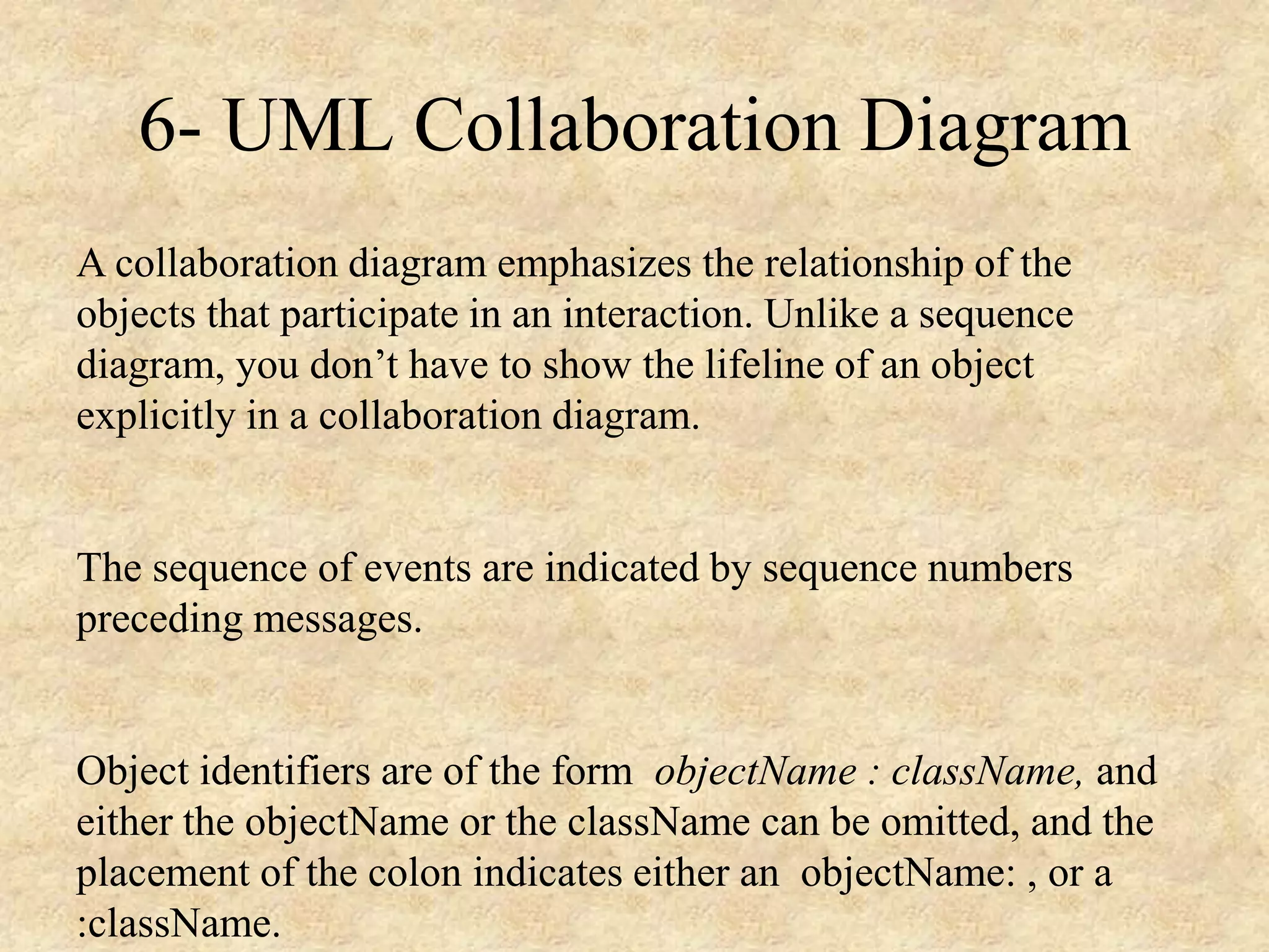
![Collaboration Diagram : Order Entry Window : Order : Order Line :Delivery Item : Stock Item :Reorder Item 1: prepare() 2*: prepare() 3: check() 4: [check == true] remove() 6: new7: [check == true] new 5: needToReorder() Self-Delegation Object Message Sequence Number](https://image.slidesharecdn.com/lec-7-uml-200214105447/75/Software-Engineering-Lec-7-uml-20-2048.jpg)