Downloaded 129 times
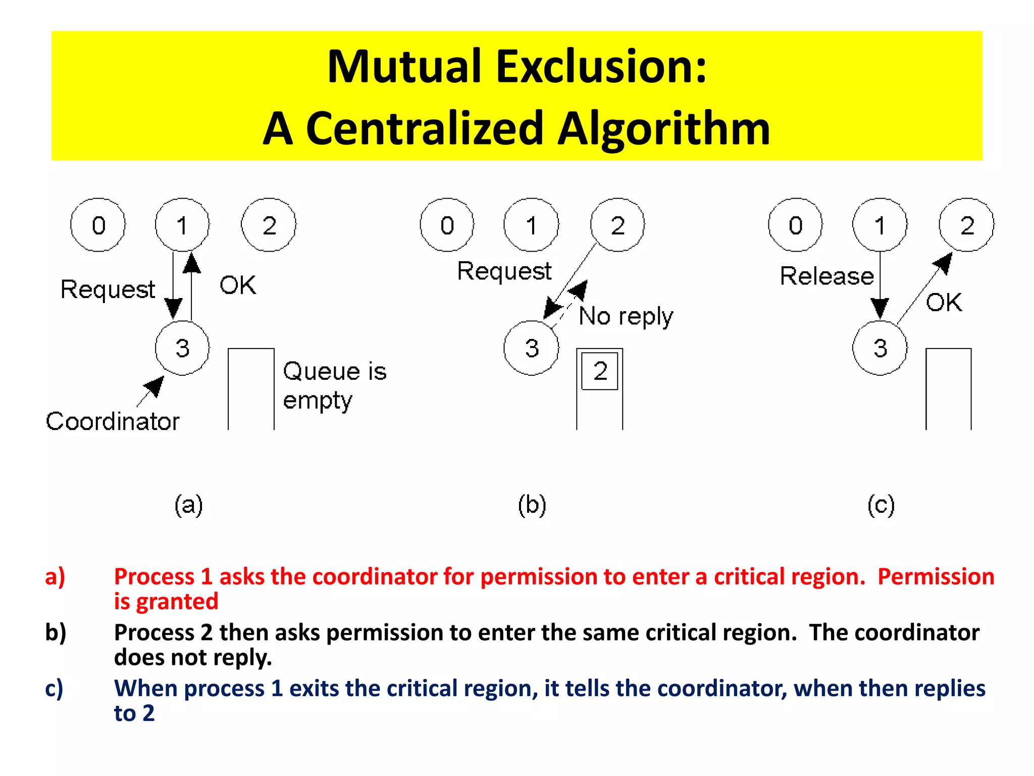
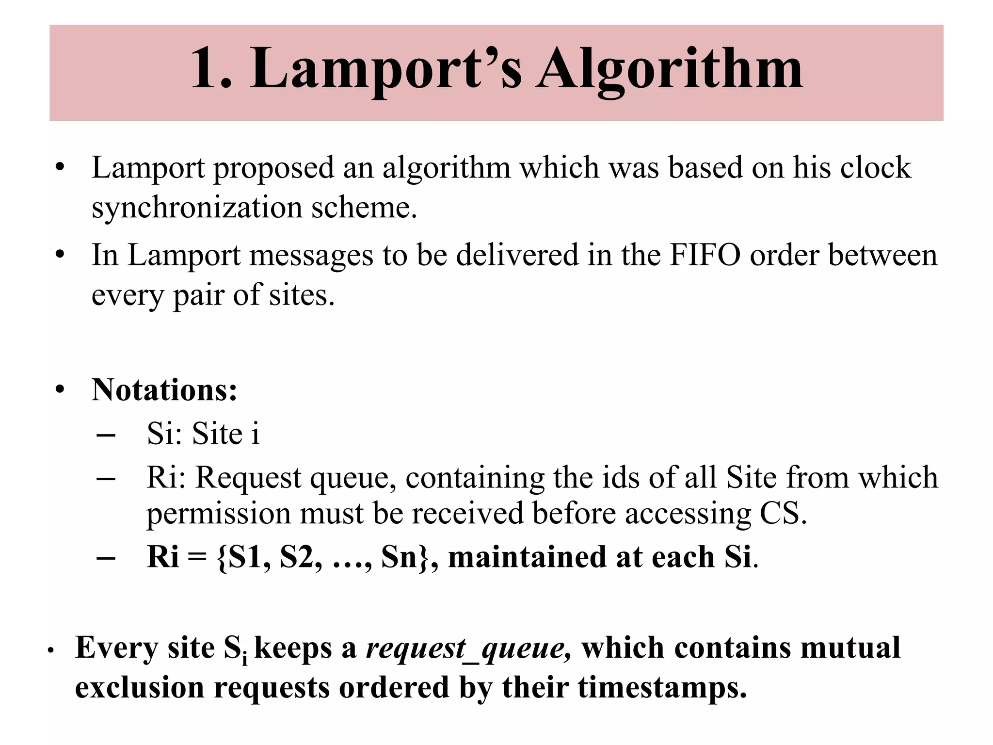
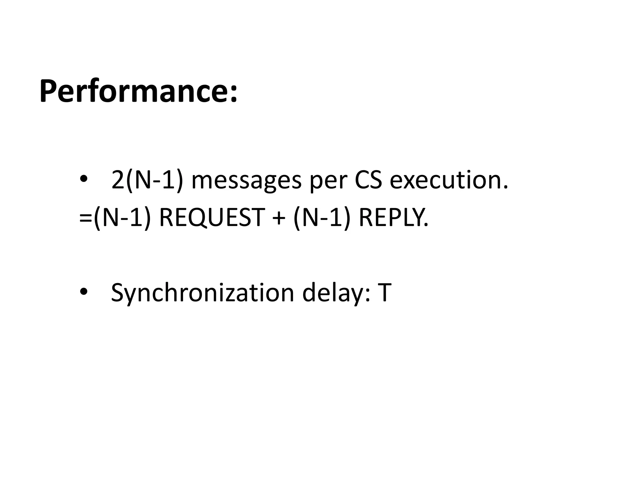
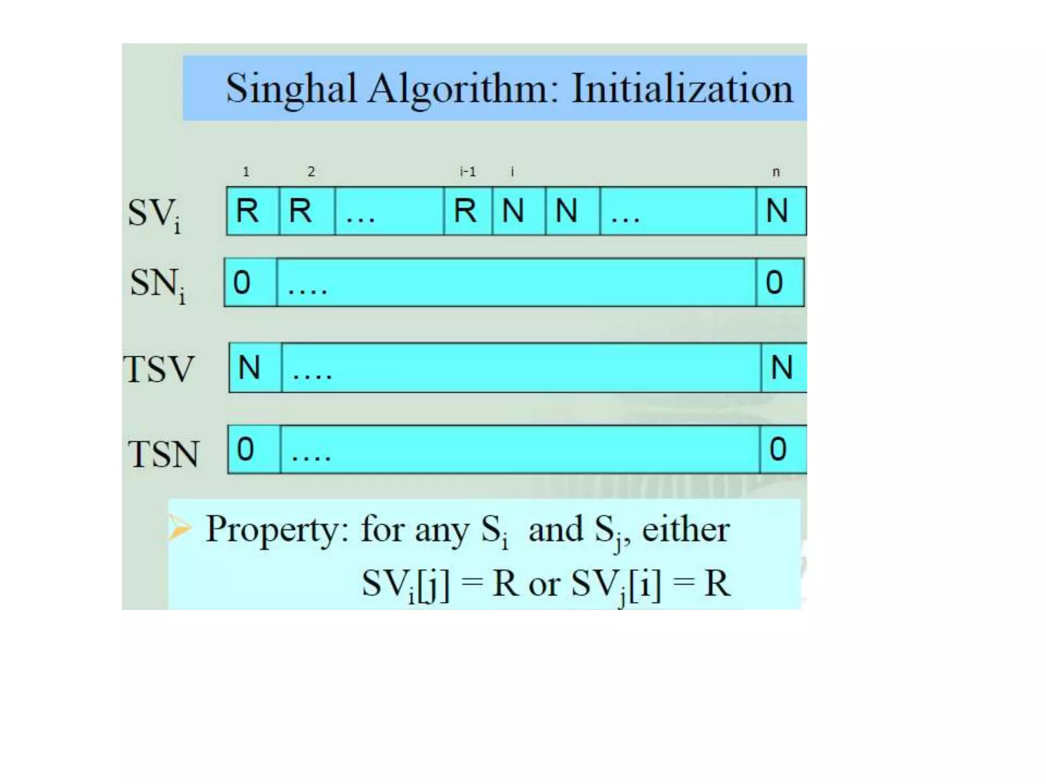
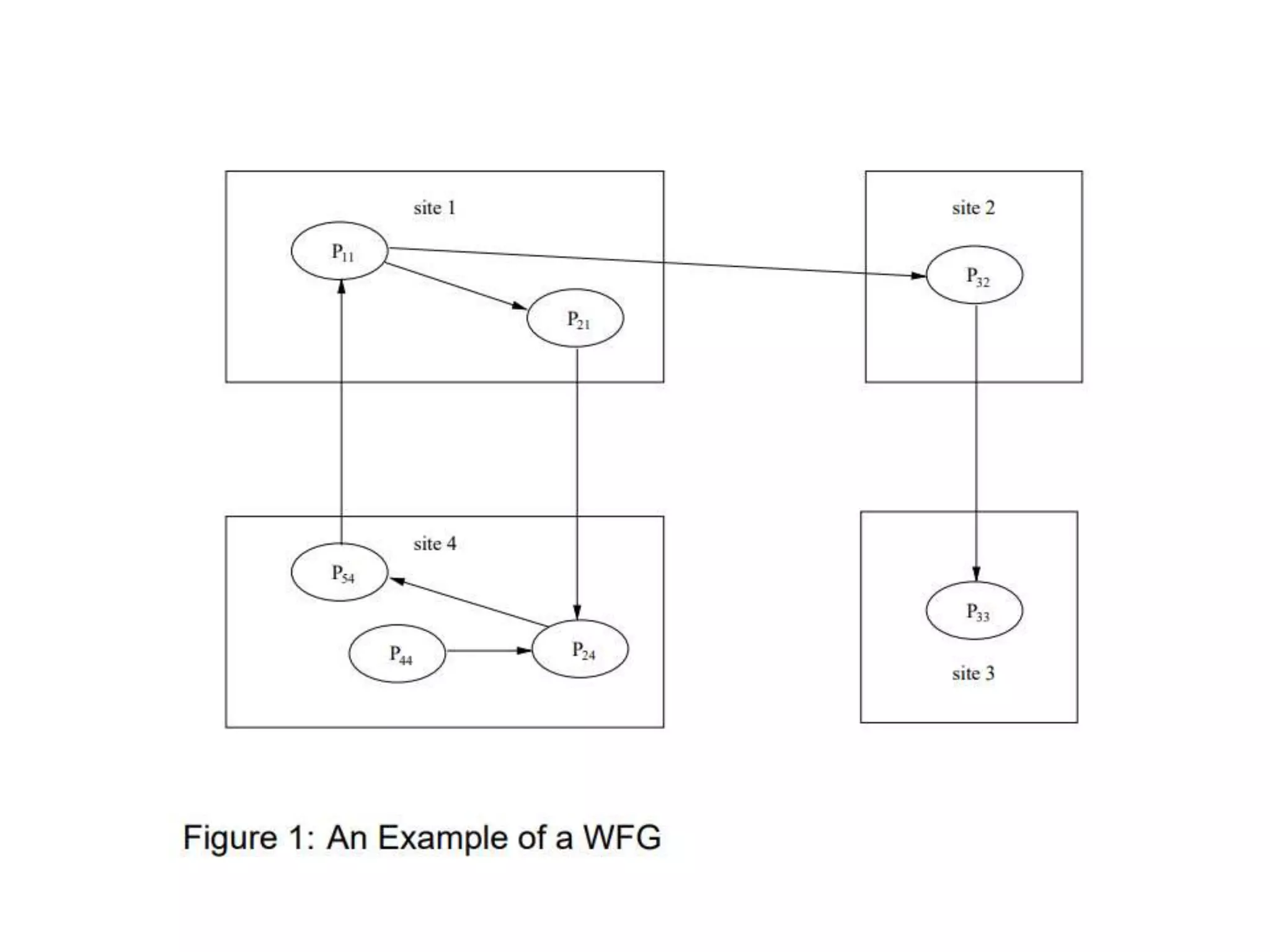
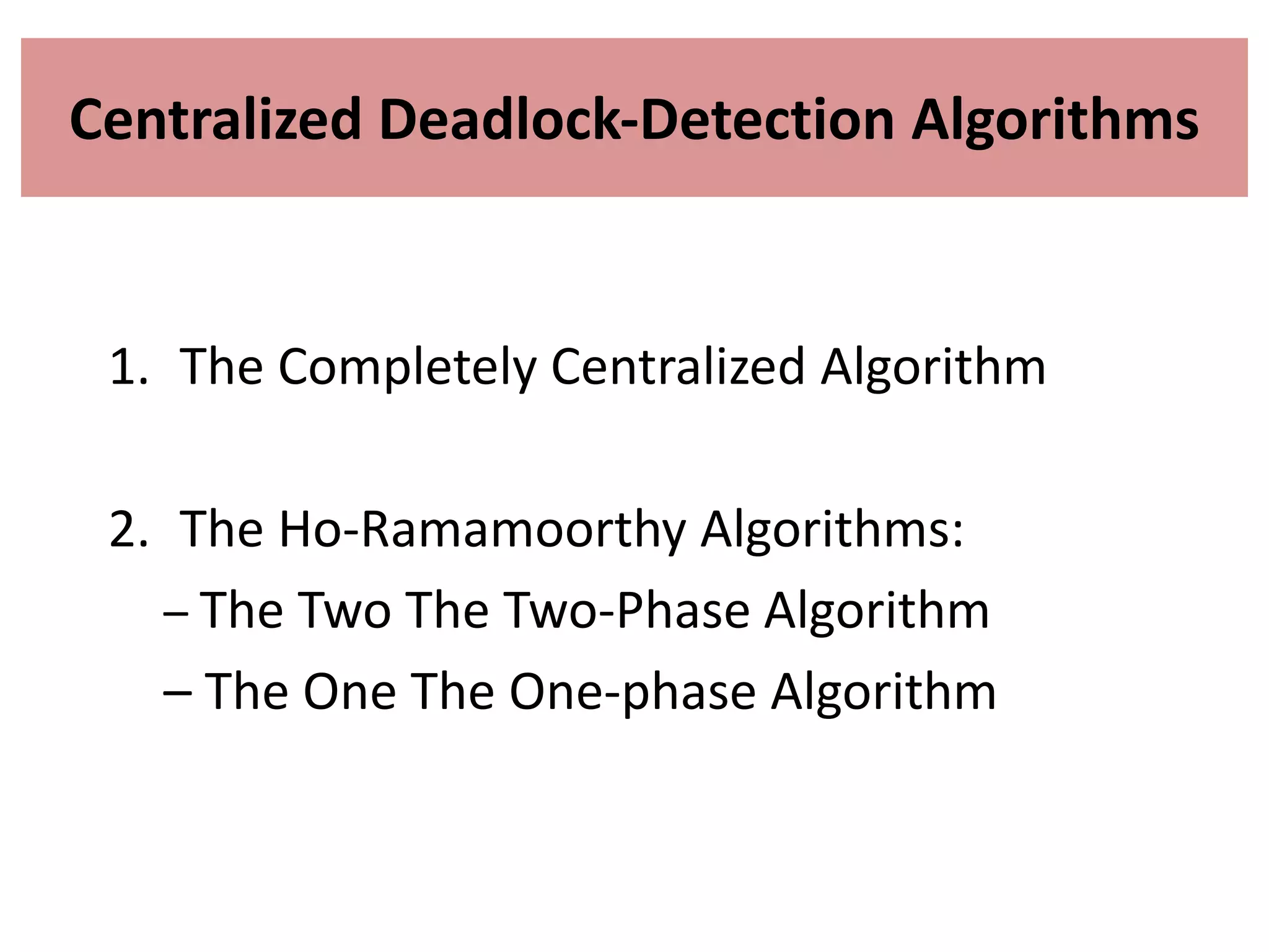
![2. THE RICART-AGRAWALA ALGORITHM • The Ricart Agrawala algorithm is an optimization of Lamport’s algorithm. • It dispenses with RELEASE messages by cleverly merging them with the REPLY messages. • Each process pi maintains the Request-Deferred array, RDi , the size of which is the same as the number of processes in the system. • Initially, ∀i ∀j: RDi [j]=0. Whenever pi defer the request sent by pj , it sets RDi [j]=1 and after it has sent a REPLY message to pj , it sets RDi [j]=0.](https://image.slidesharecdn.com/3-190924095026/75/Distributed-Mutual-Exclusion-and-Distributed-Deadlock-Detection-25-2048.jpg)
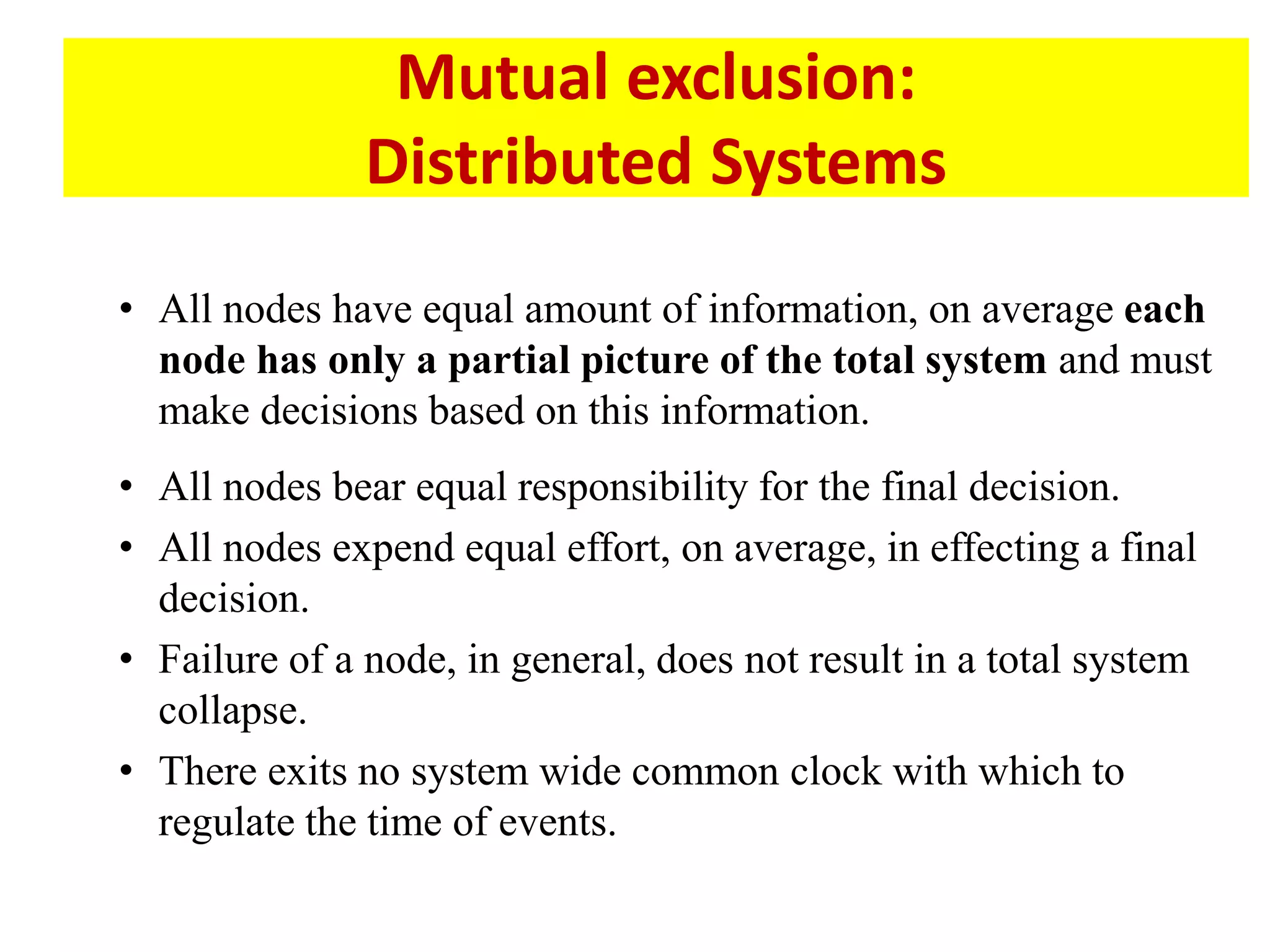
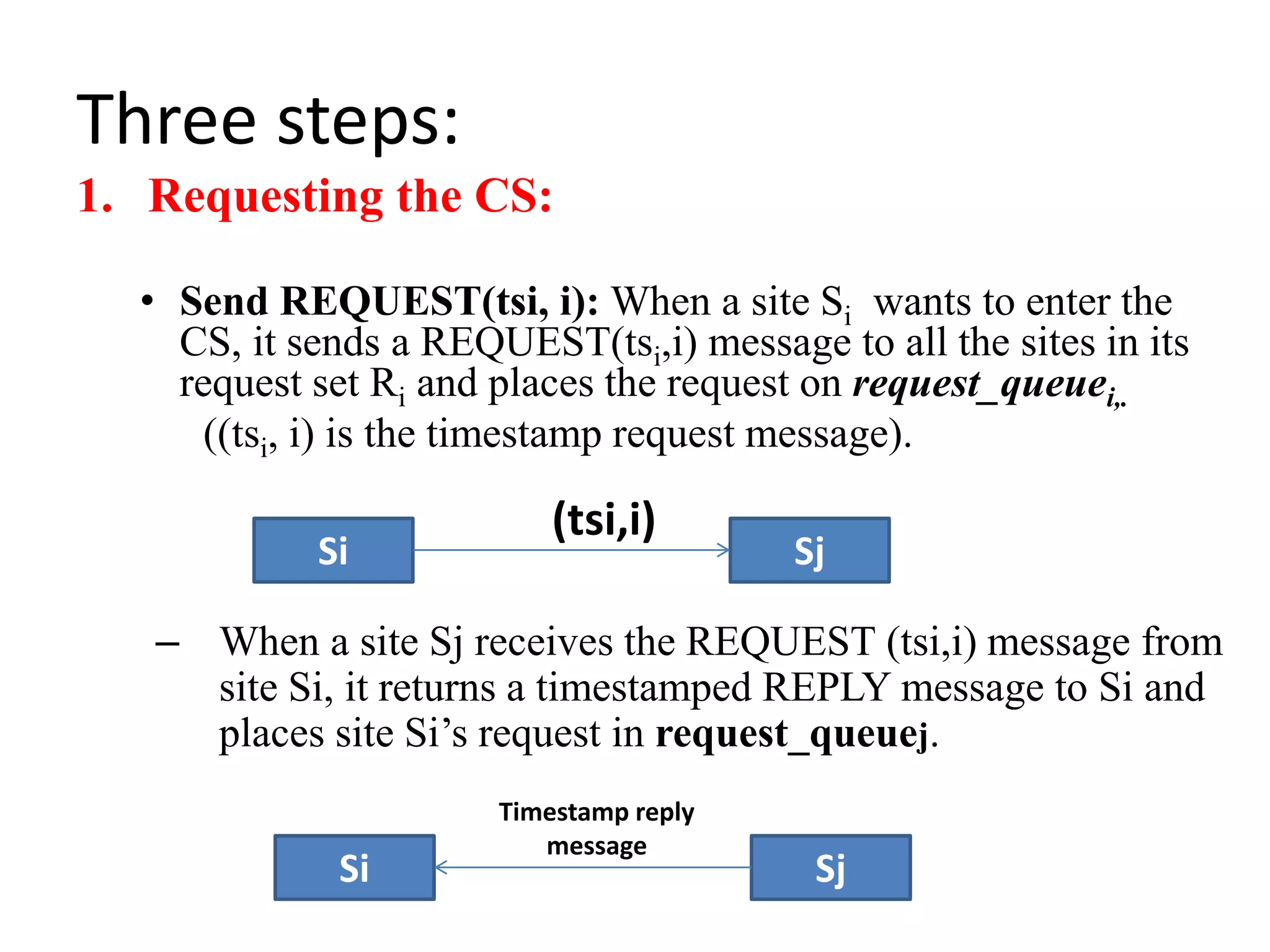
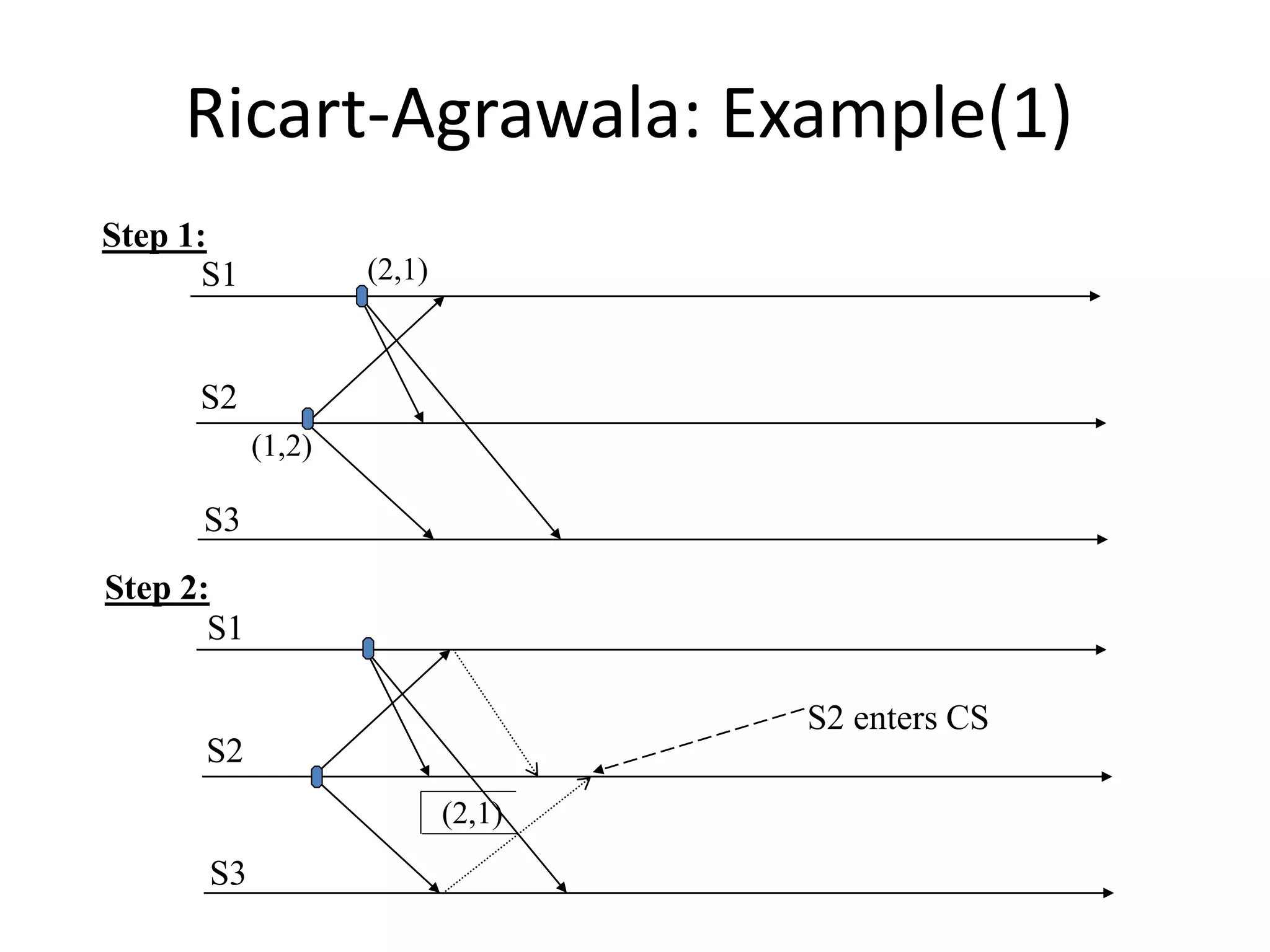
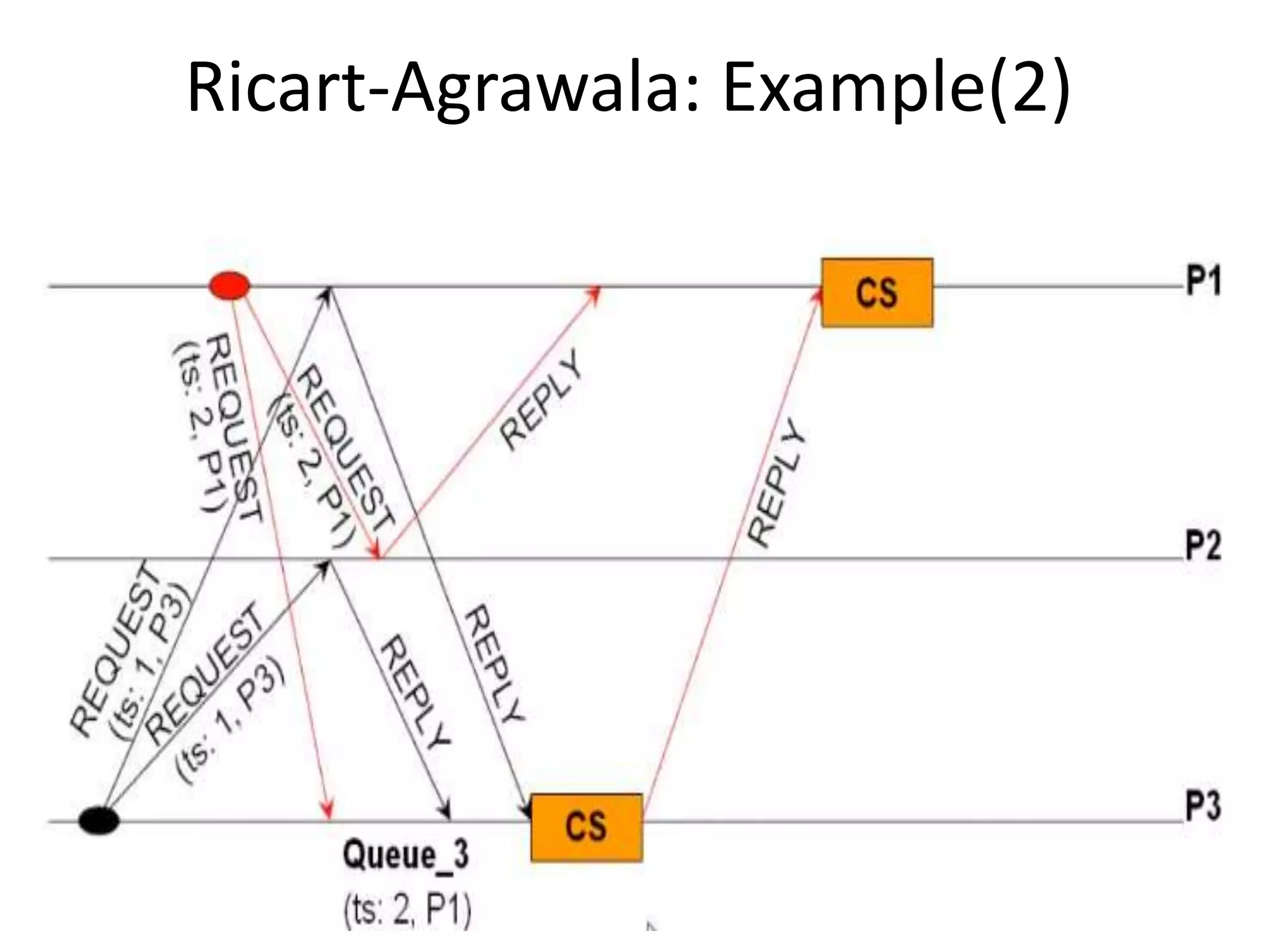
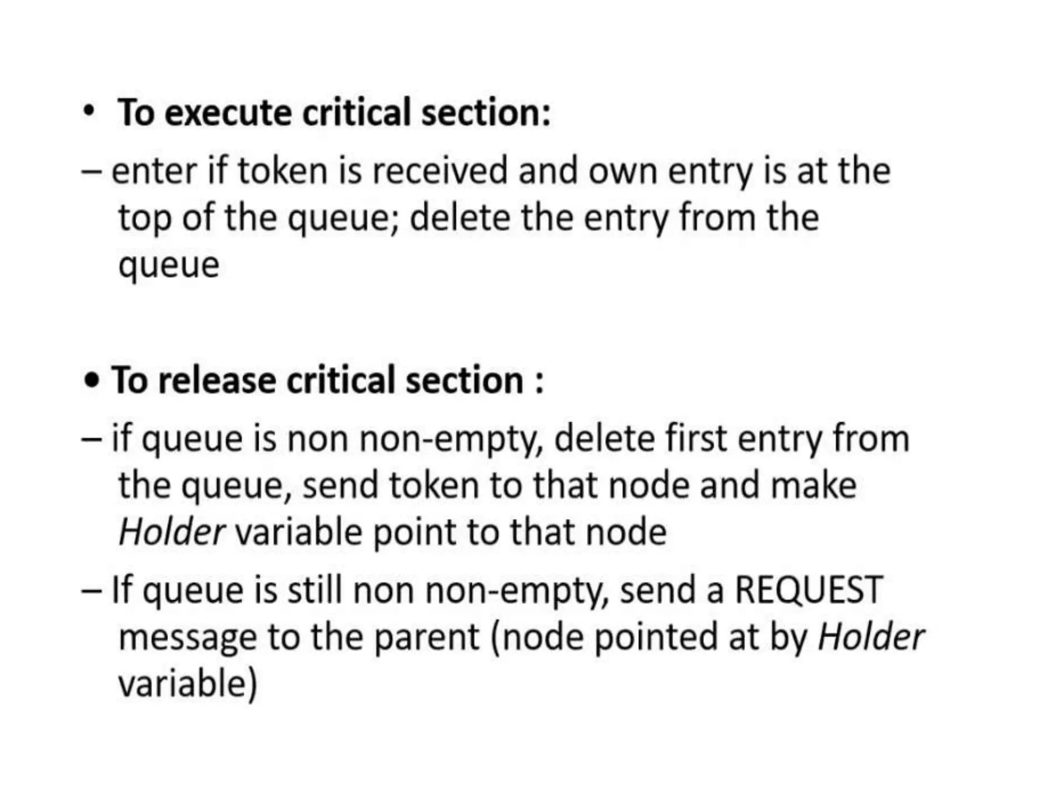
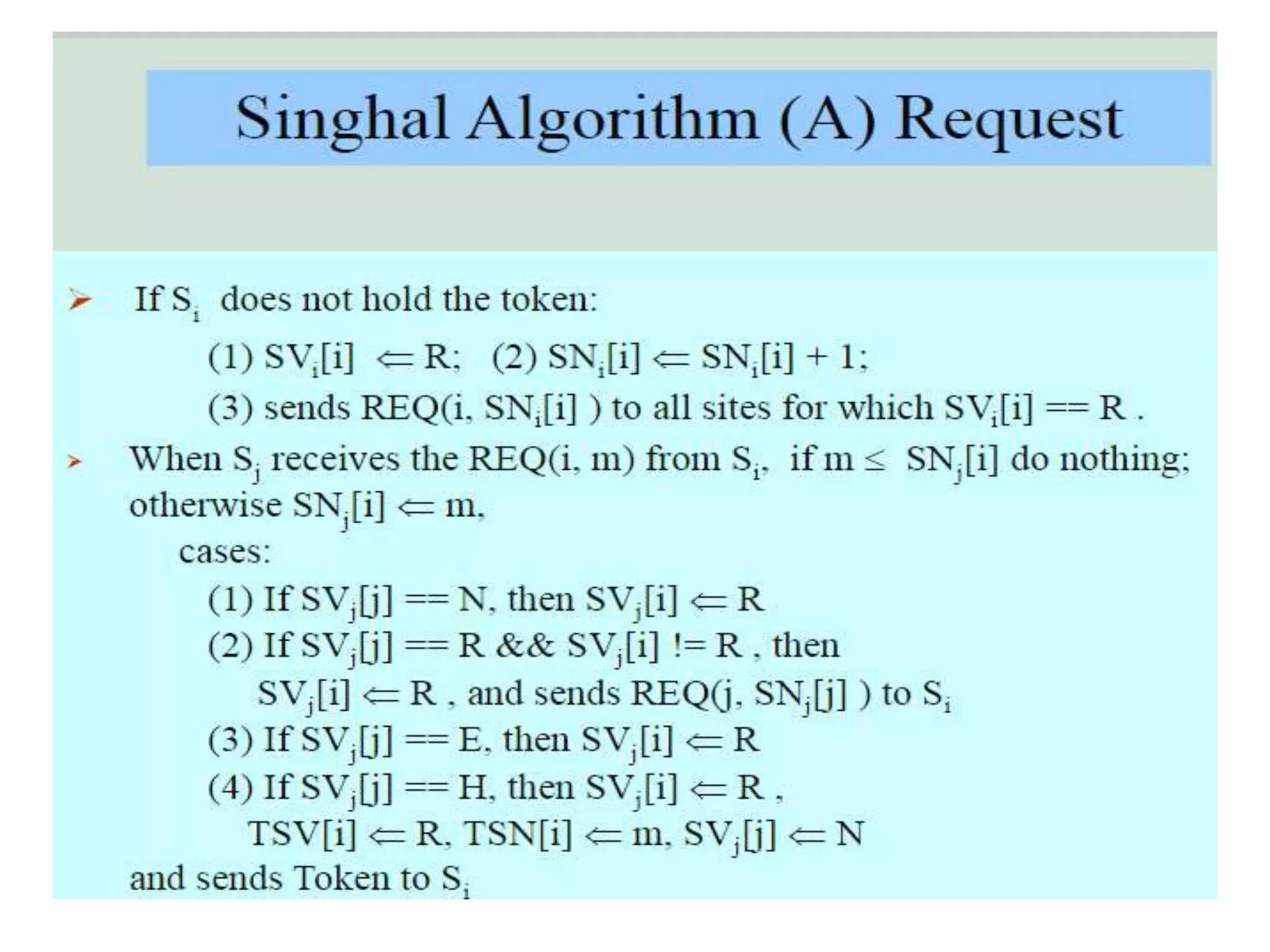
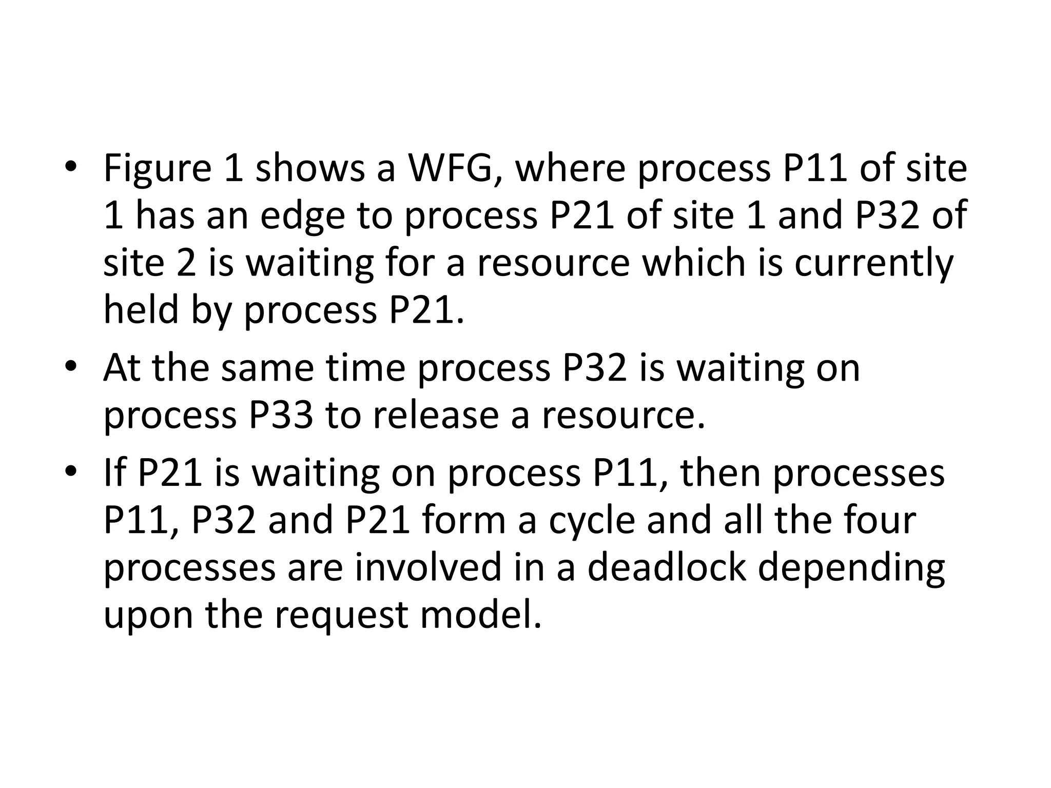
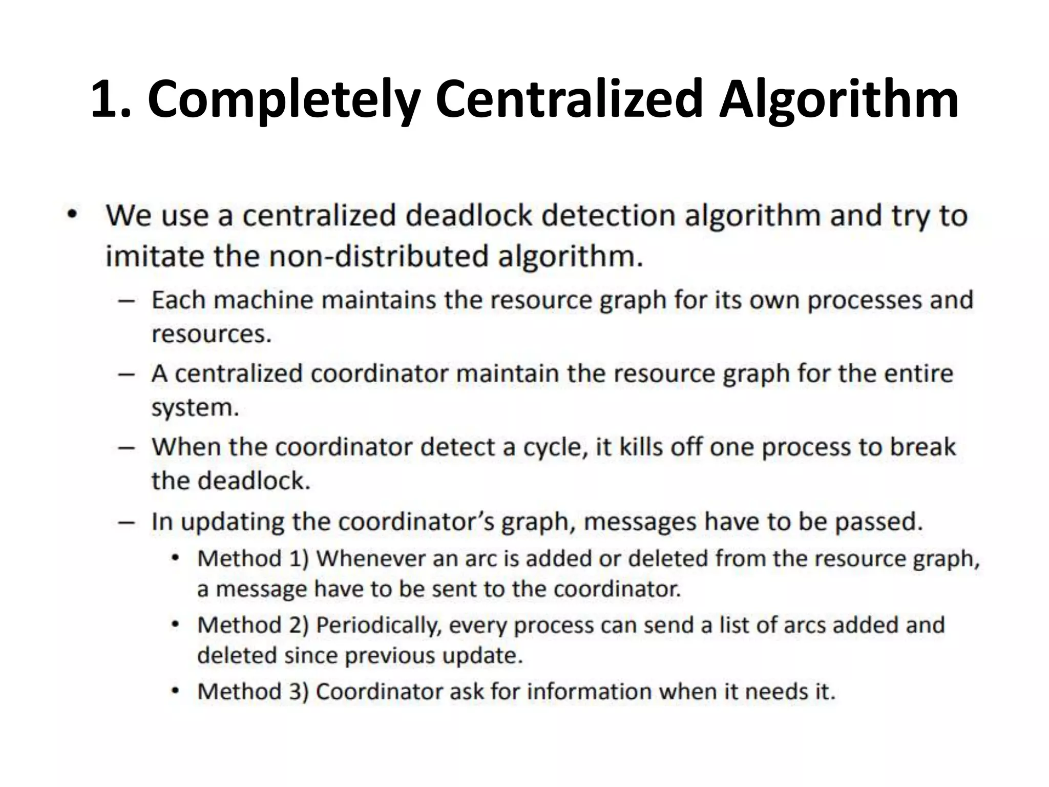
![Three Steps: 1. Requesting the critical section : – When a site Si wants to enter the CS, it sends the time stamped REQUEST message to all sites. – Sj sends REPLY to Si, if • Sj is not requesting nor executing CS • If Sj is requesting CS and Si’s time stamp is smaller than its own request. Otherwise, the reply is deferred and Sj sets RDj [i]=1](https://image.slidesharecdn.com/3-190924095026/75/Distributed-Mutual-Exclusion-and-Distributed-Deadlock-Detection-26-2048.jpg)
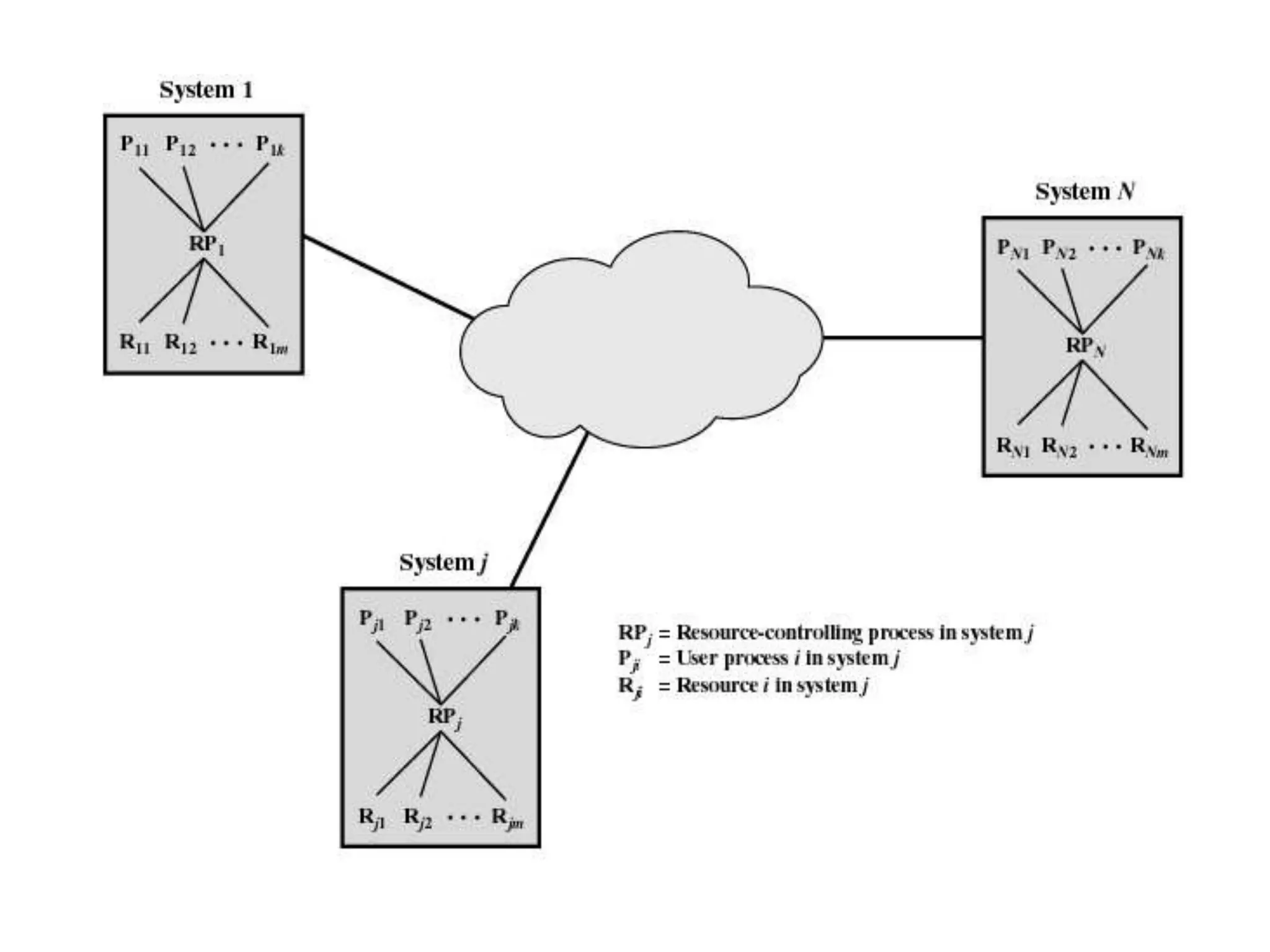
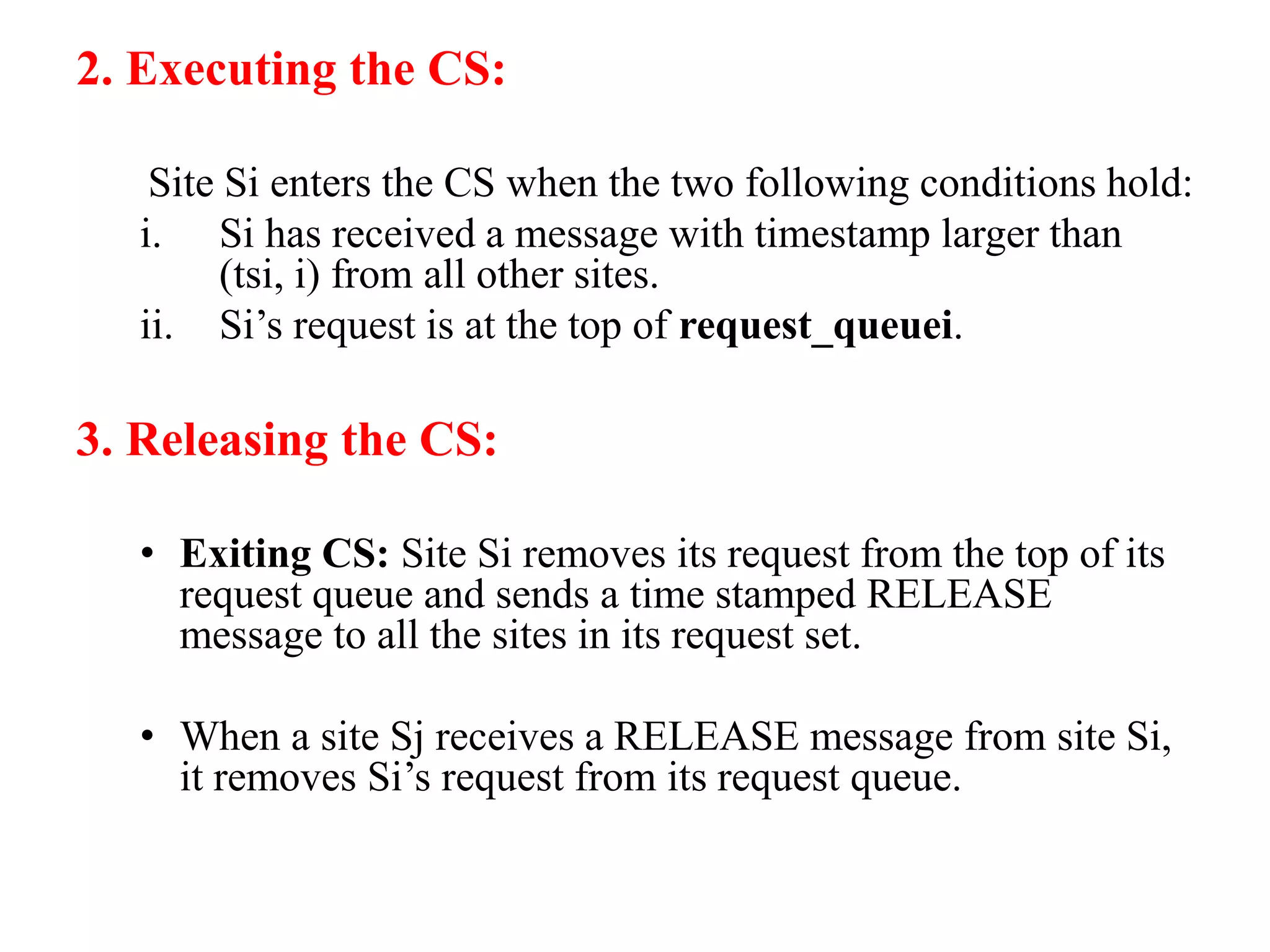
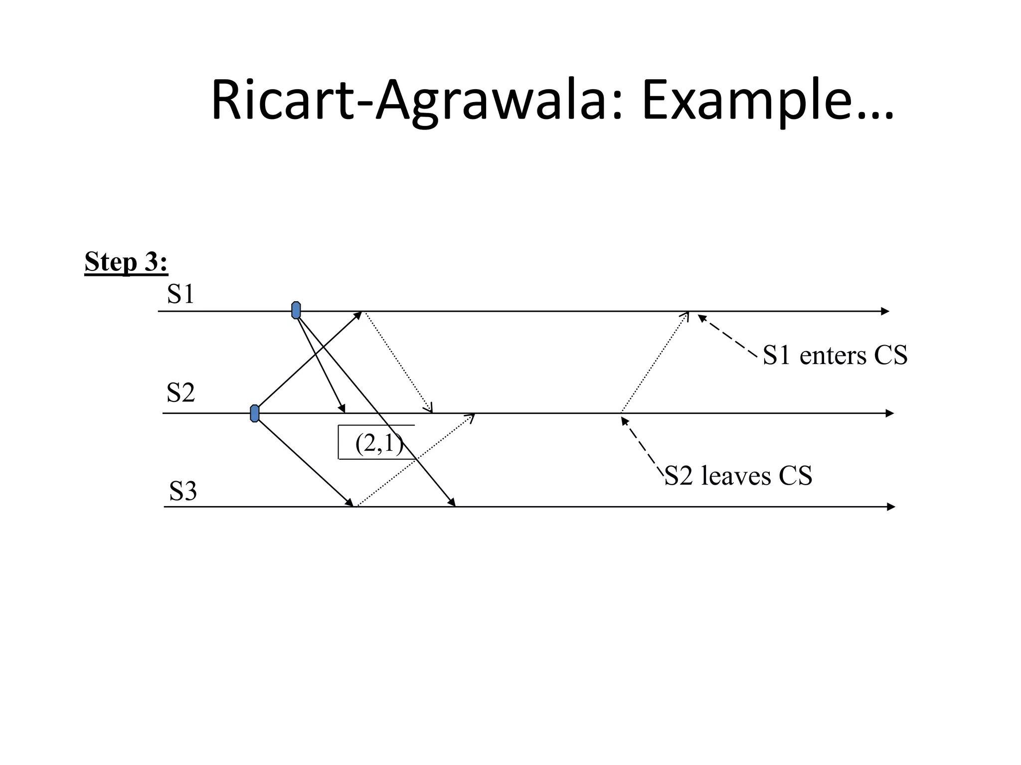
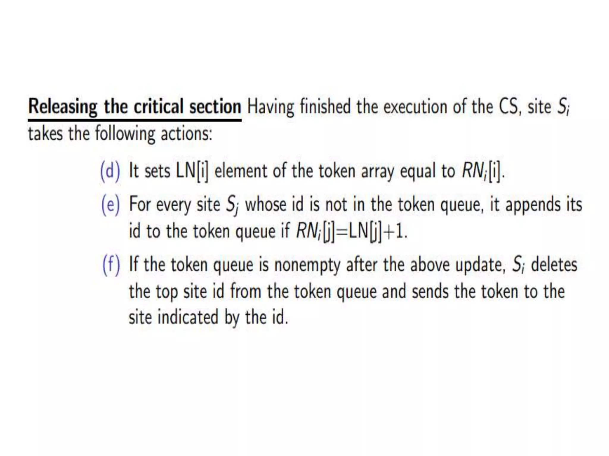
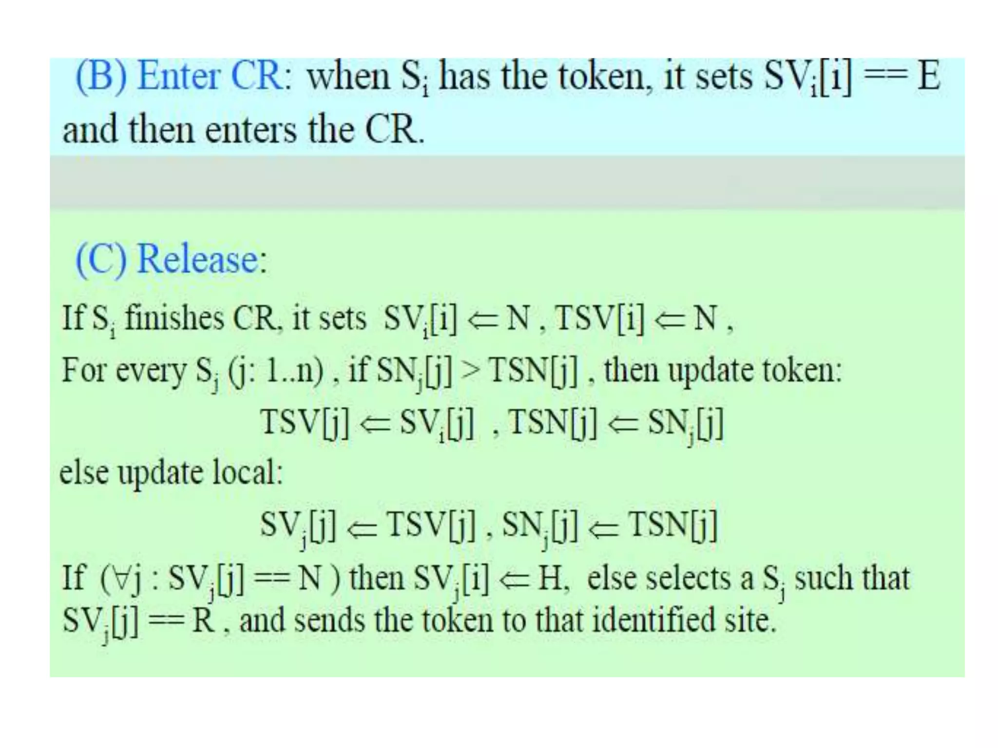
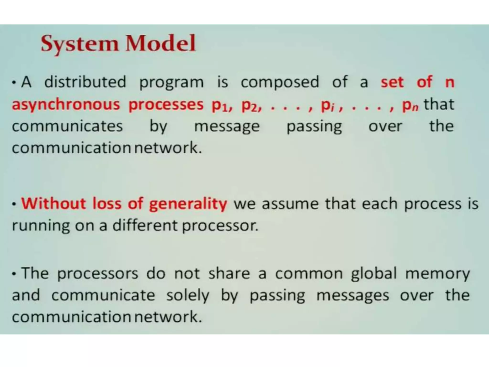
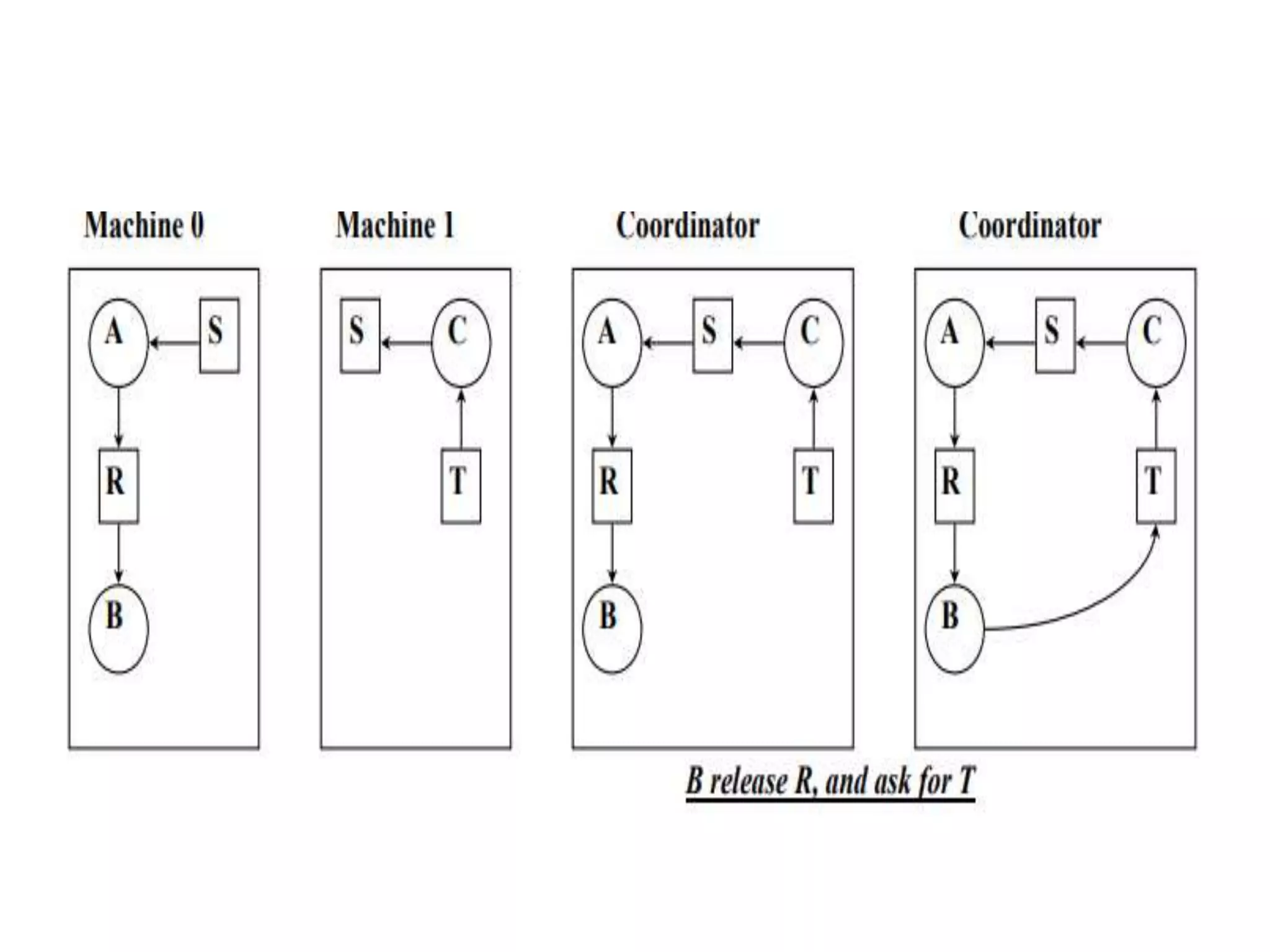
![2. Executing the CS: – Site Si enters the CS after it has received REPLY messages from all the sites in its request set. 3. Releasing the CS: – When site Si exits the CS, it sends all the deferred REPLY messages: ∀j if RDi [j]=1, then send a REPLY message to Sj and set RDi [j]=0. – i.e., a site’s REPLY messages are blocked only by sites with smaller time stamps](https://image.slidesharecdn.com/3-190924095026/75/Distributed-Mutual-Exclusion-and-Distributed-Deadlock-Detection-27-2048.jpg)
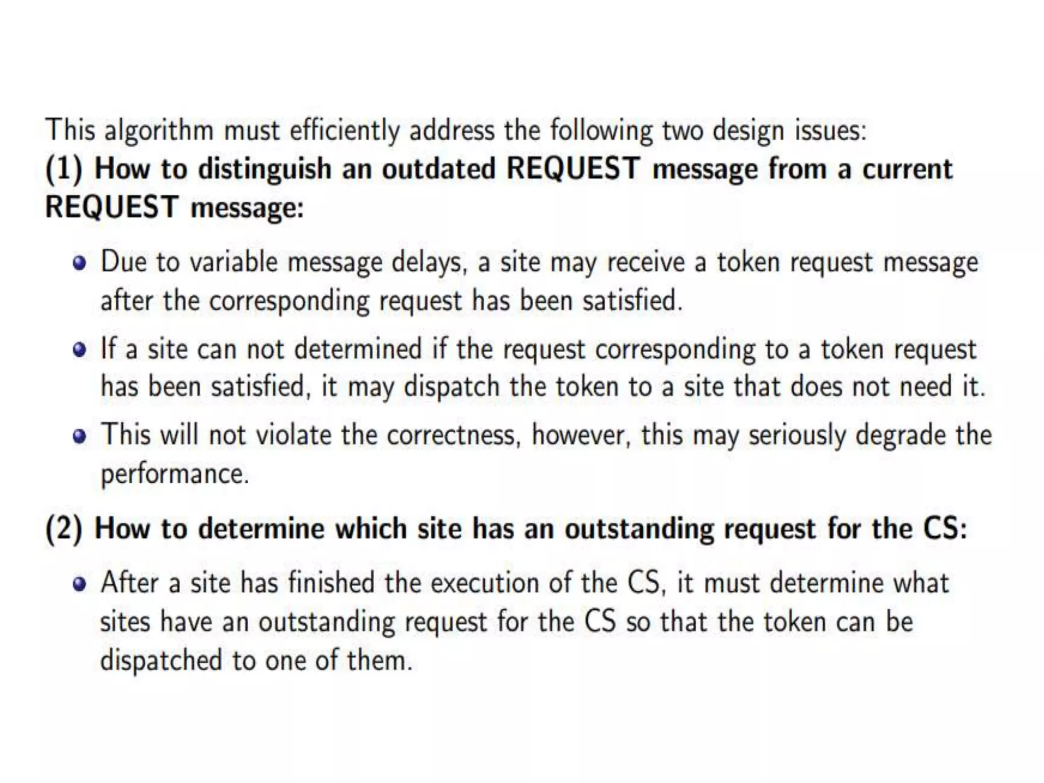
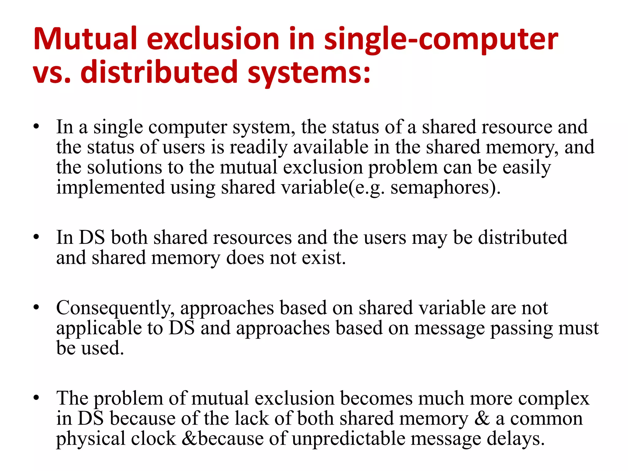
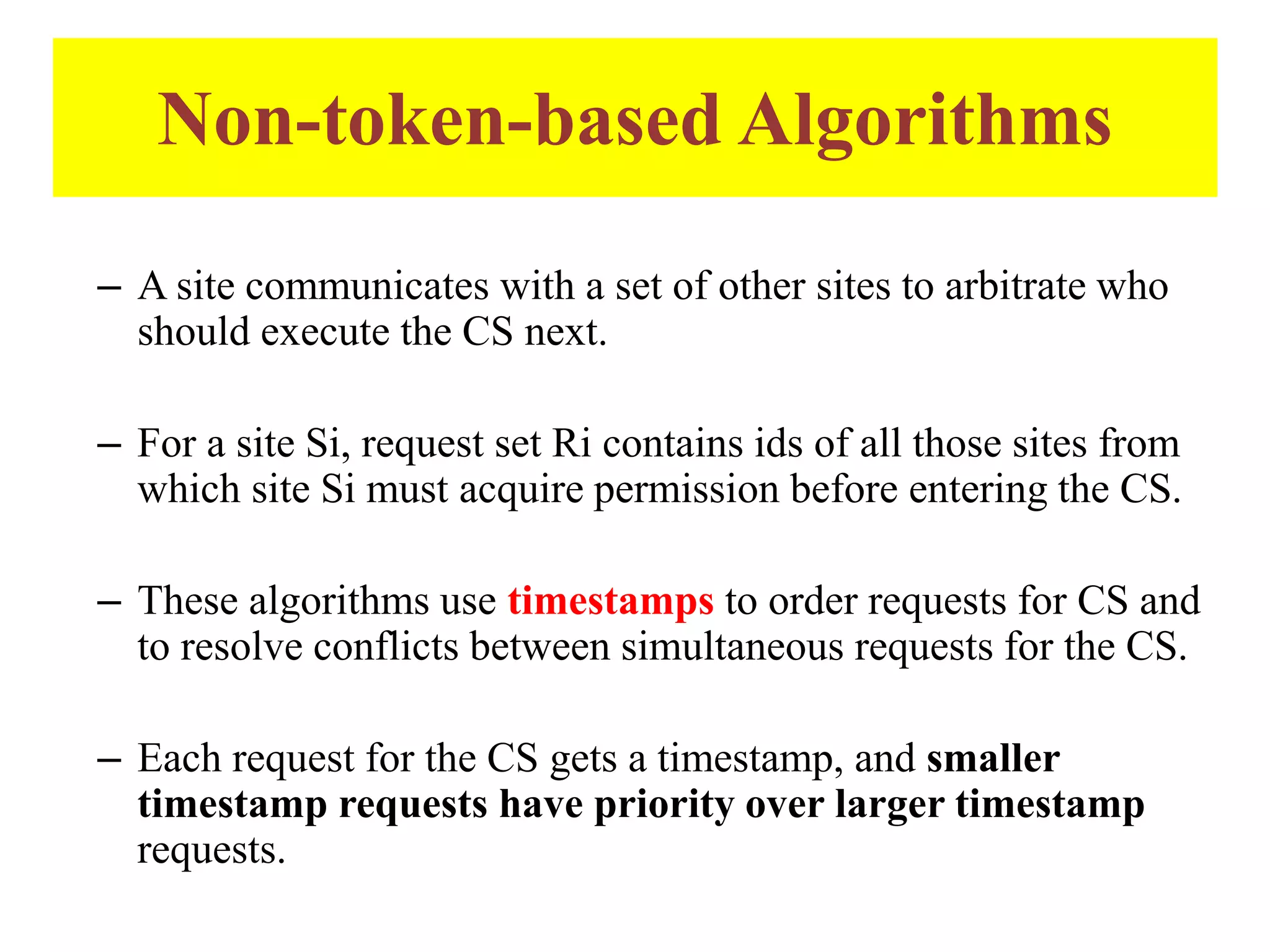
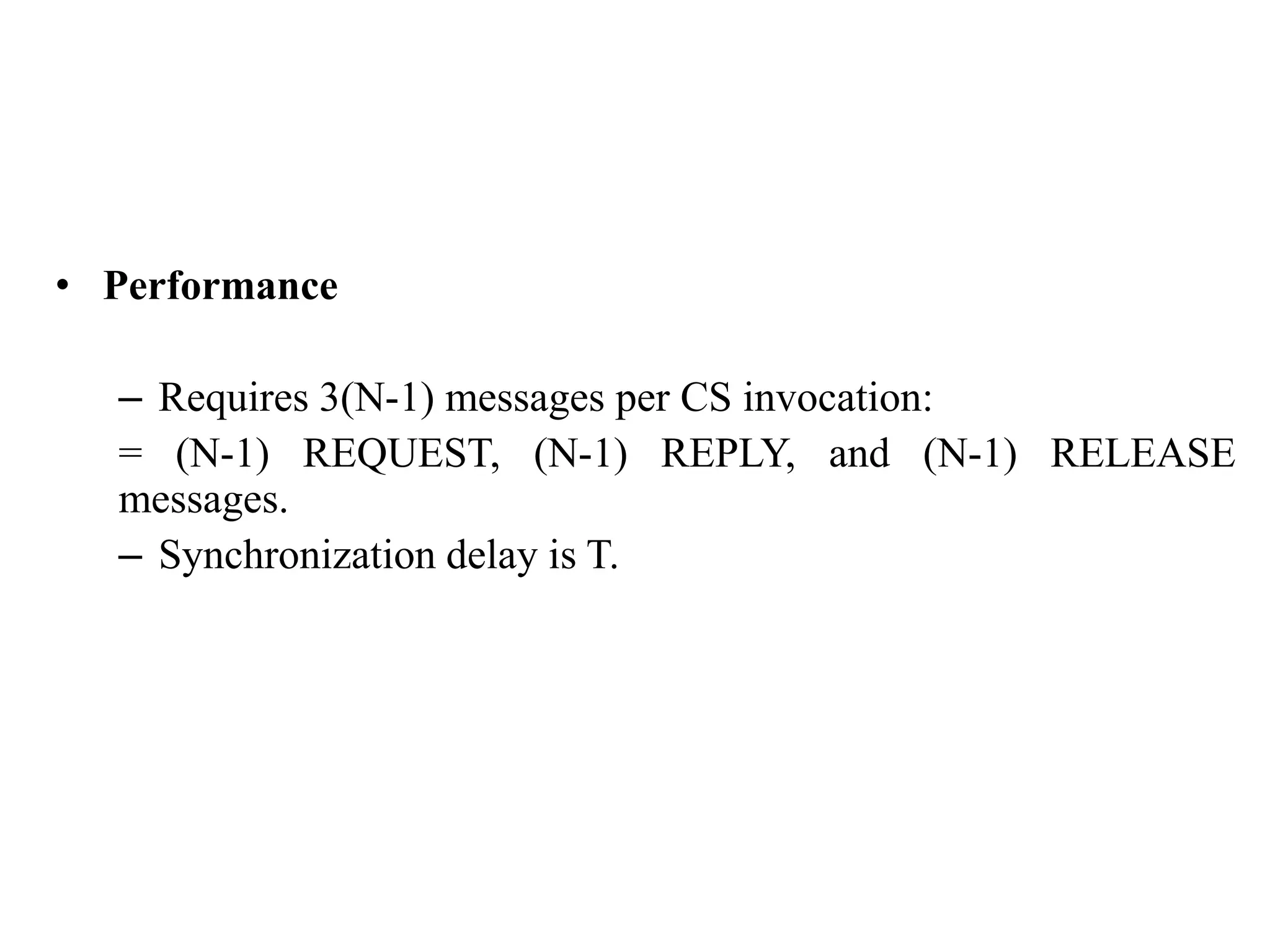
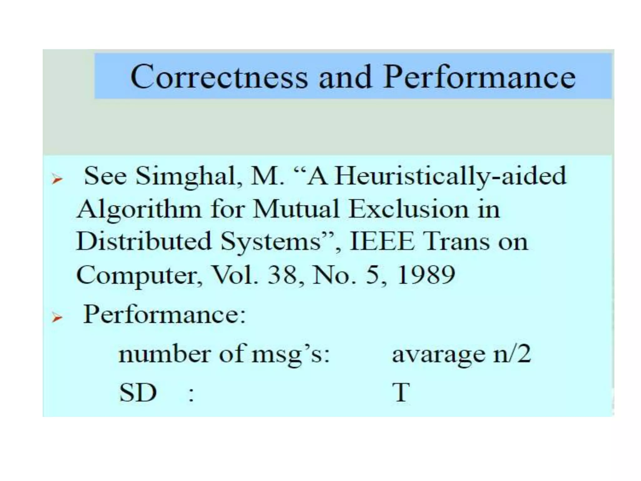
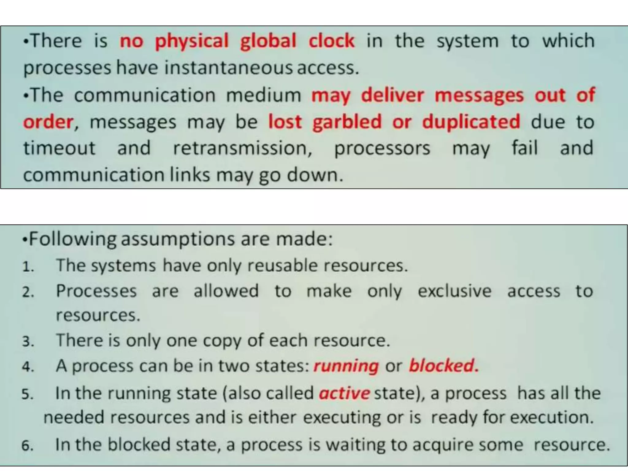
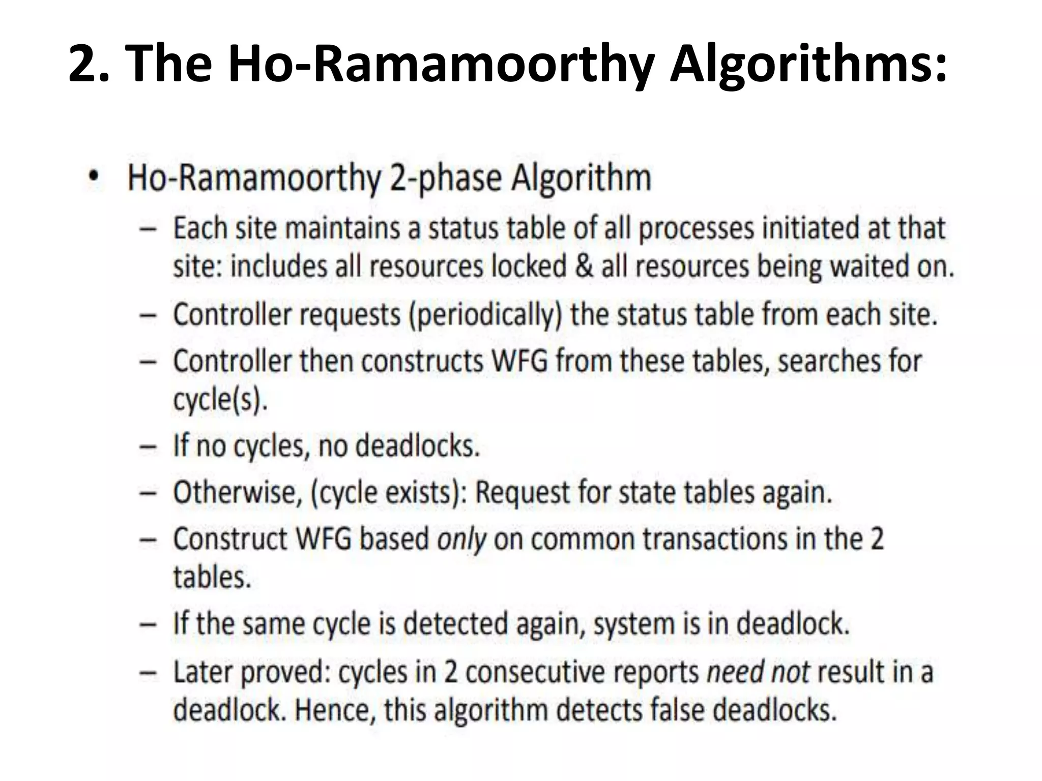
![Process i broadcasts (i, num) Each process maintains -an array req: req[j] denotes the sequence no of the latest request from process j Additionally, the holder of the token maintains -an array last: last[j] denotes the sequence number of the latest visit to CS for process j. - a queue Q of waiting processes req: array[0..n-1] of integer last: array [0..n-1] of integer Sequence number of the request req req req req req last queue Q](https://image.slidesharecdn.com/3-190924095026/75/Distributed-Mutual-Exclusion-and-Distributed-Deadlock-Detection-45-2048.jpg)
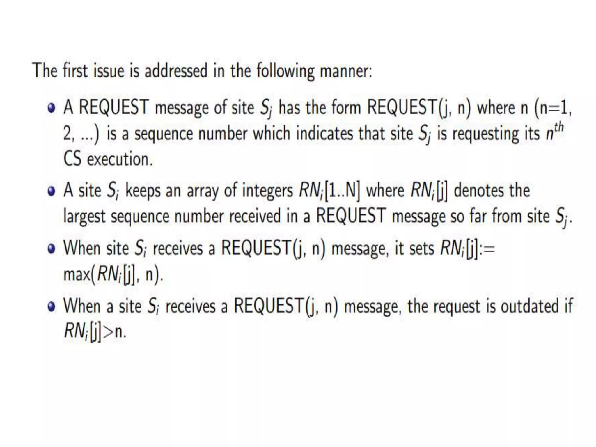
![Suzuki-Kasami’s Broadcast Algorithm: Example 0 2 1 3 4 req=[1,0,0,0,0] last=[0,0,0,0,0] req=[1,0,0,0,0] req=[1,0,0,0,0] req=[1,0,0,0,0] req=[1,0,0,0,0] initial state: process 0 has sent a request to all, and grabbed the token](https://image.slidesharecdn.com/3-190924095026/75/Distributed-Mutual-Exclusion-and-Distributed-Deadlock-Detection-50-2048.jpg)
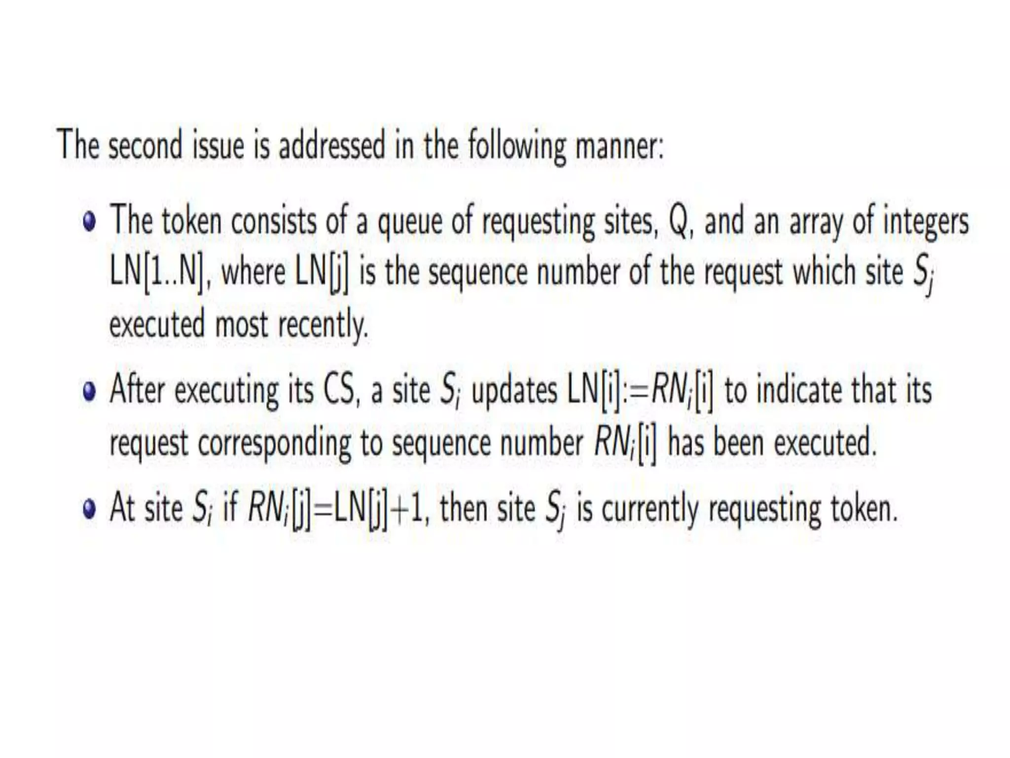
![0 2 1 3 4 req=[1,1,1,0,0] last=[0,0,0,0,0] req=[1,1,1,0,0] req=[1,1,1,0,0] req=[1,1,1,0,0] req=[1,1,1,0,0] 1 & 2 send requests to enter CS](https://image.slidesharecdn.com/3-190924095026/75/Distributed-Mutual-Exclusion-and-Distributed-Deadlock-Detection-51-2048.jpg)
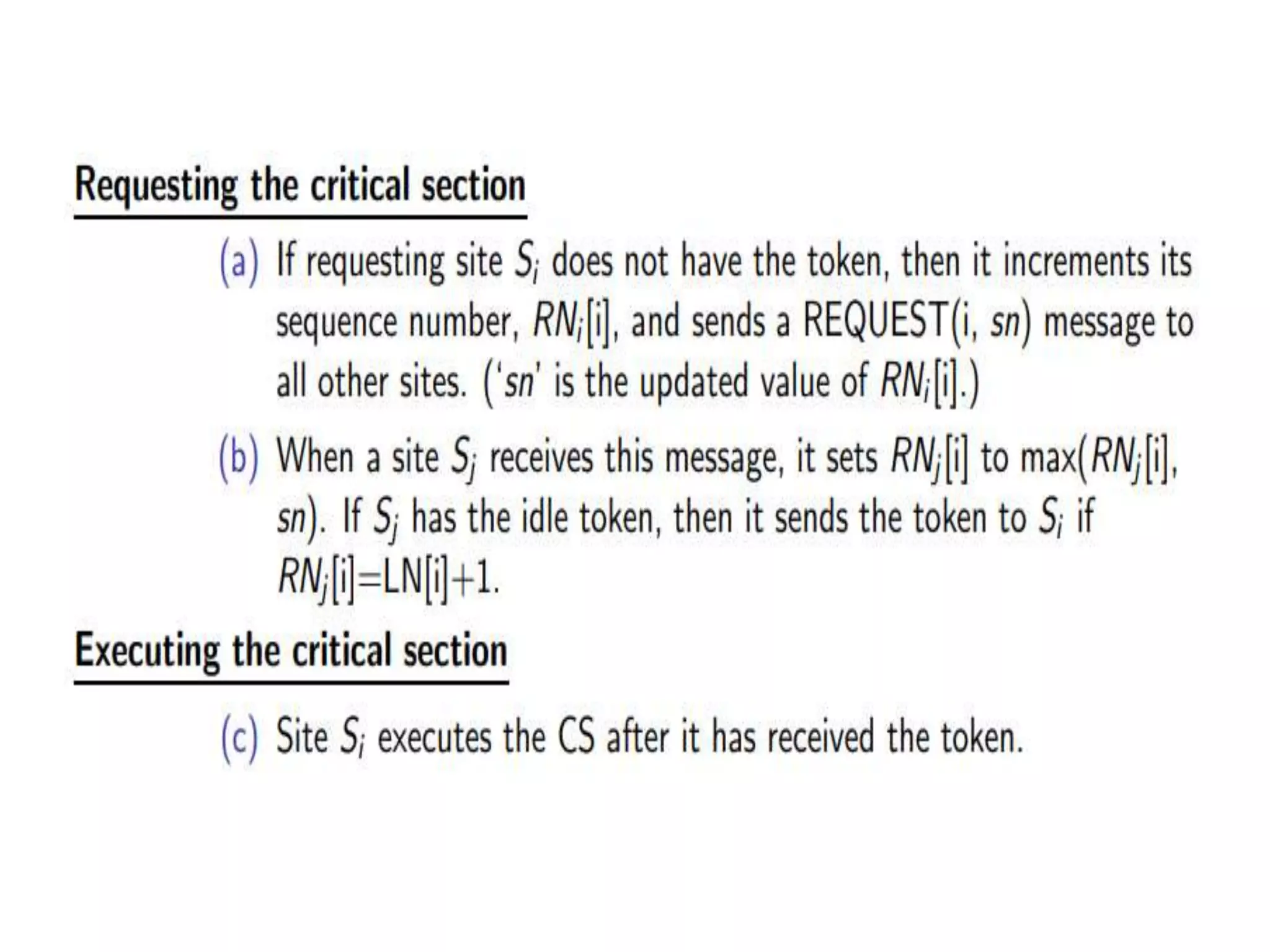
![0 2 1 3 4 req=[1,1,1,0,0] last=[1,0,0,0,0] Q=(1,2) req=[1,1,1,0,0] req=[1,1,1,0,0] req=[1,1,1,0,0] req=[1,1,1,0,0] 0 prepares to exit CS](https://image.slidesharecdn.com/3-190924095026/75/Distributed-Mutual-Exclusion-and-Distributed-Deadlock-Detection-52-2048.jpg)
![0 2 1 3 4 req=[1,1,1,0,0] req=[1,1,1,0,0] last=[1,0,0,0,0] Q=(2) req=[1,1,1,0,0] req=[1,1,1,0,0] req=[1,1,1,0,0] 0 passes token (Q and last) to 1](https://image.slidesharecdn.com/3-190924095026/75/Distributed-Mutual-Exclusion-and-Distributed-Deadlock-Detection-53-2048.jpg)
![0 2 1 3 4 req=[2,1,1,1,0] req=[2,1,1,1,0] last=[1,0,0,0,0] Q=(2,0,3) req=[2,1,1,1,0] req=[2,1,1,1,0] req=[2,1,1,1,0] 0 and 3 send requests](https://image.slidesharecdn.com/3-190924095026/75/Distributed-Mutual-Exclusion-and-Distributed-Deadlock-Detection-54-2048.jpg)
![0 2 1 3 4 req=[2,1,1,1,0] req=[2,1,1,1,0] req=[2,1,1,1,0] last=[1,1,0,0,0] Q=(0,3) req=[2,1,1,1,0] req=[2,1,1,1,0] 1 sends token to 2](https://image.slidesharecdn.com/3-190924095026/75/Distributed-Mutual-Exclusion-and-Distributed-Deadlock-Detection-55-2048.jpg)
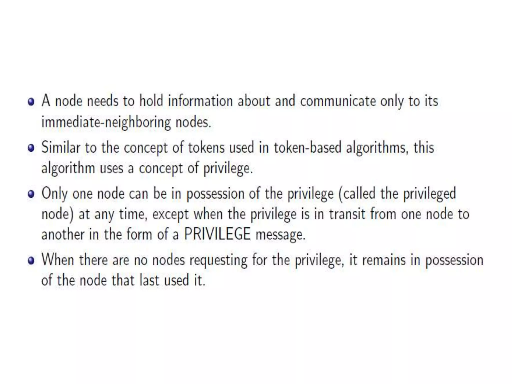
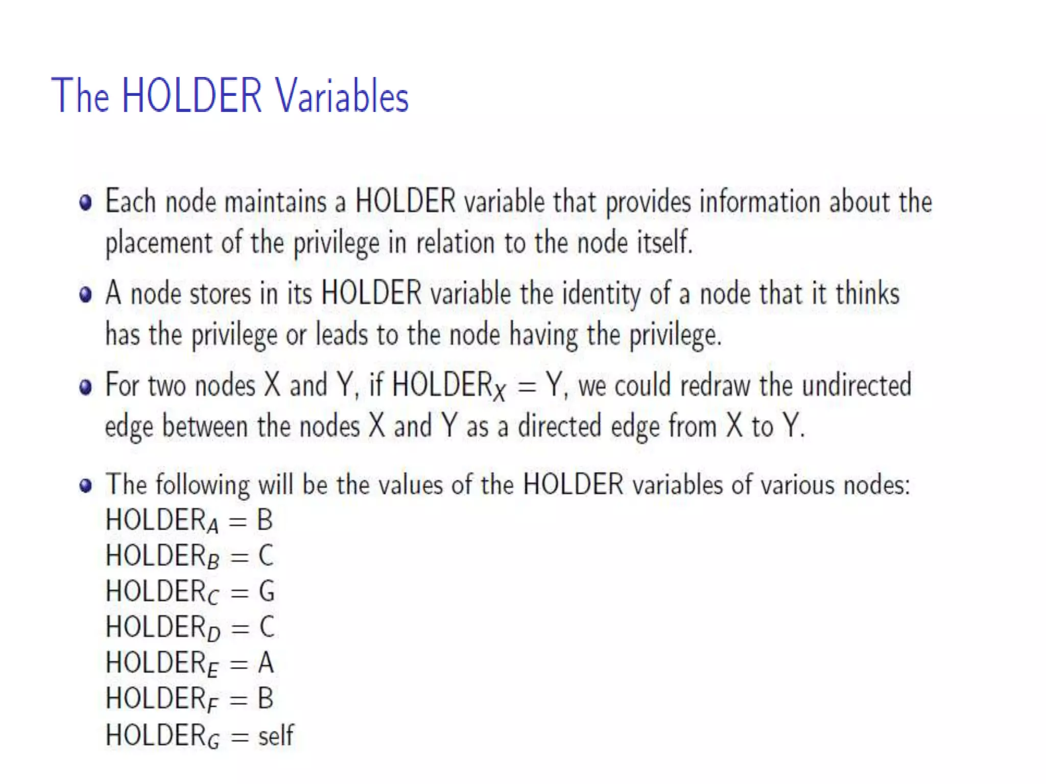
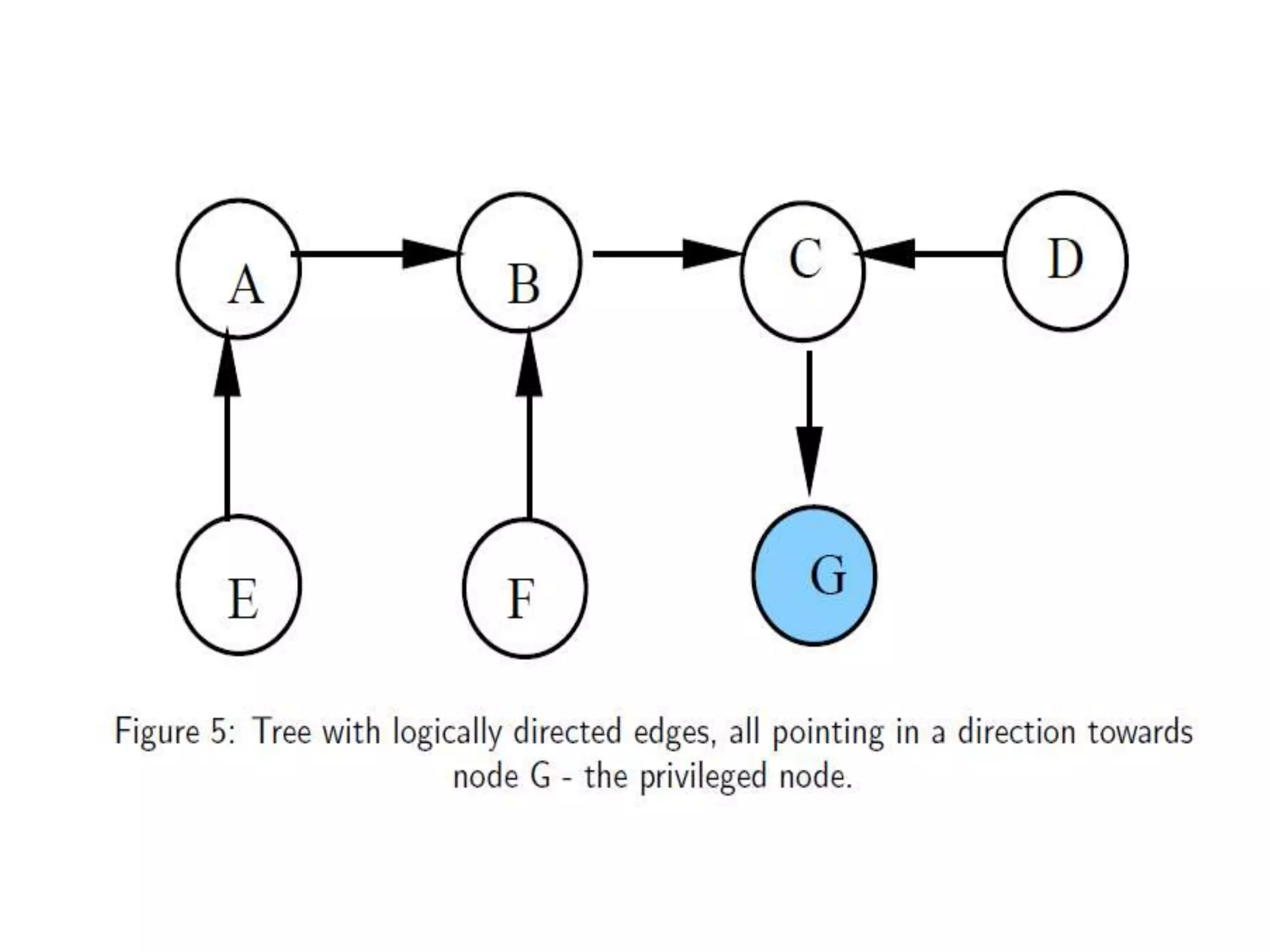
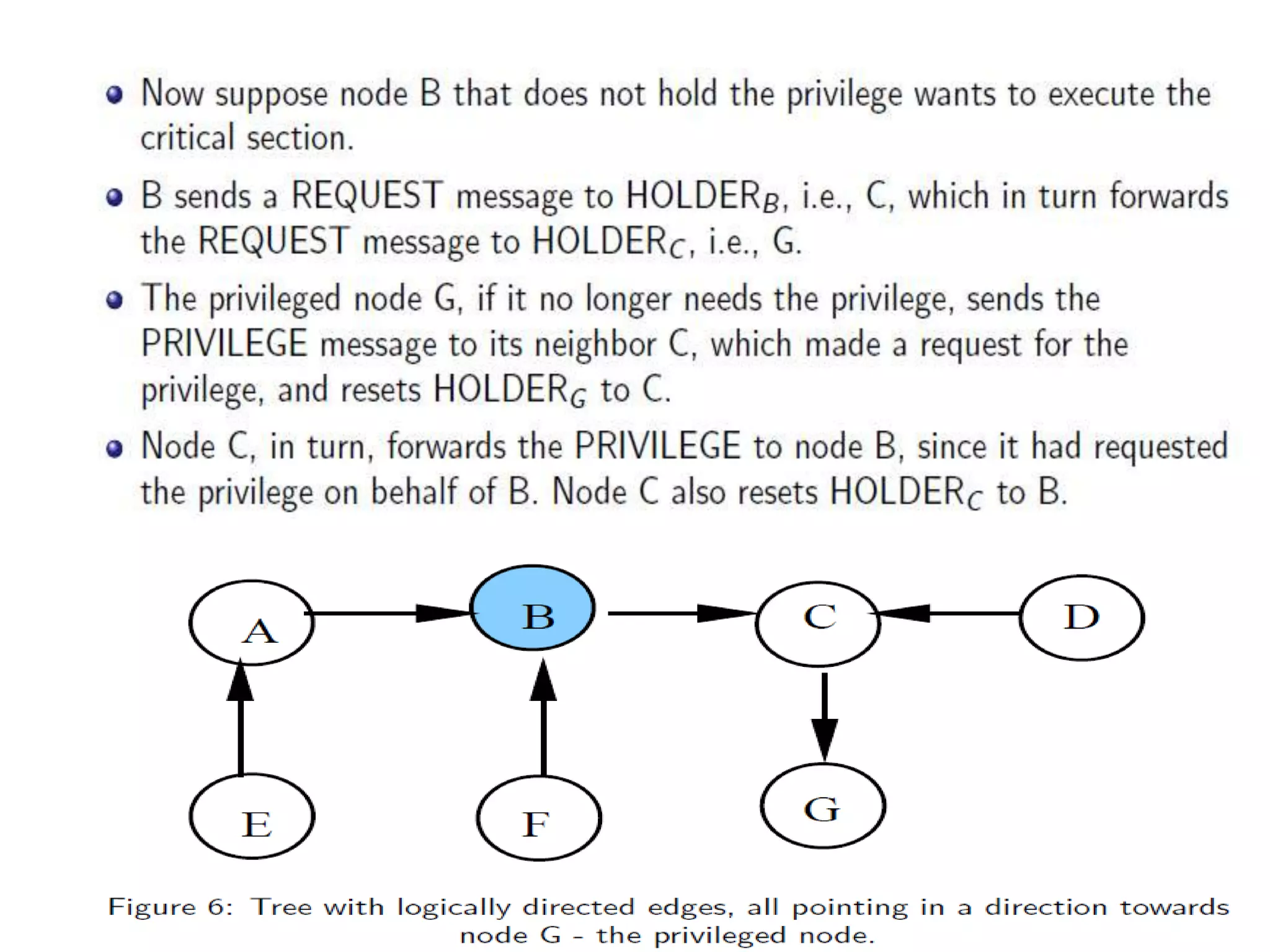
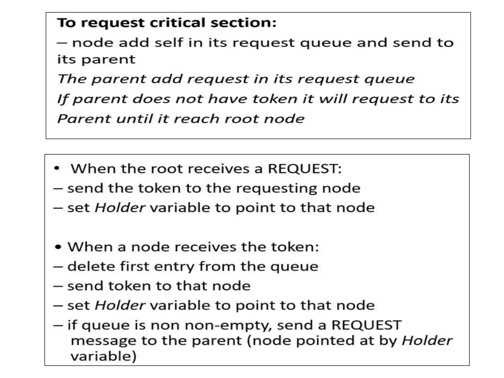
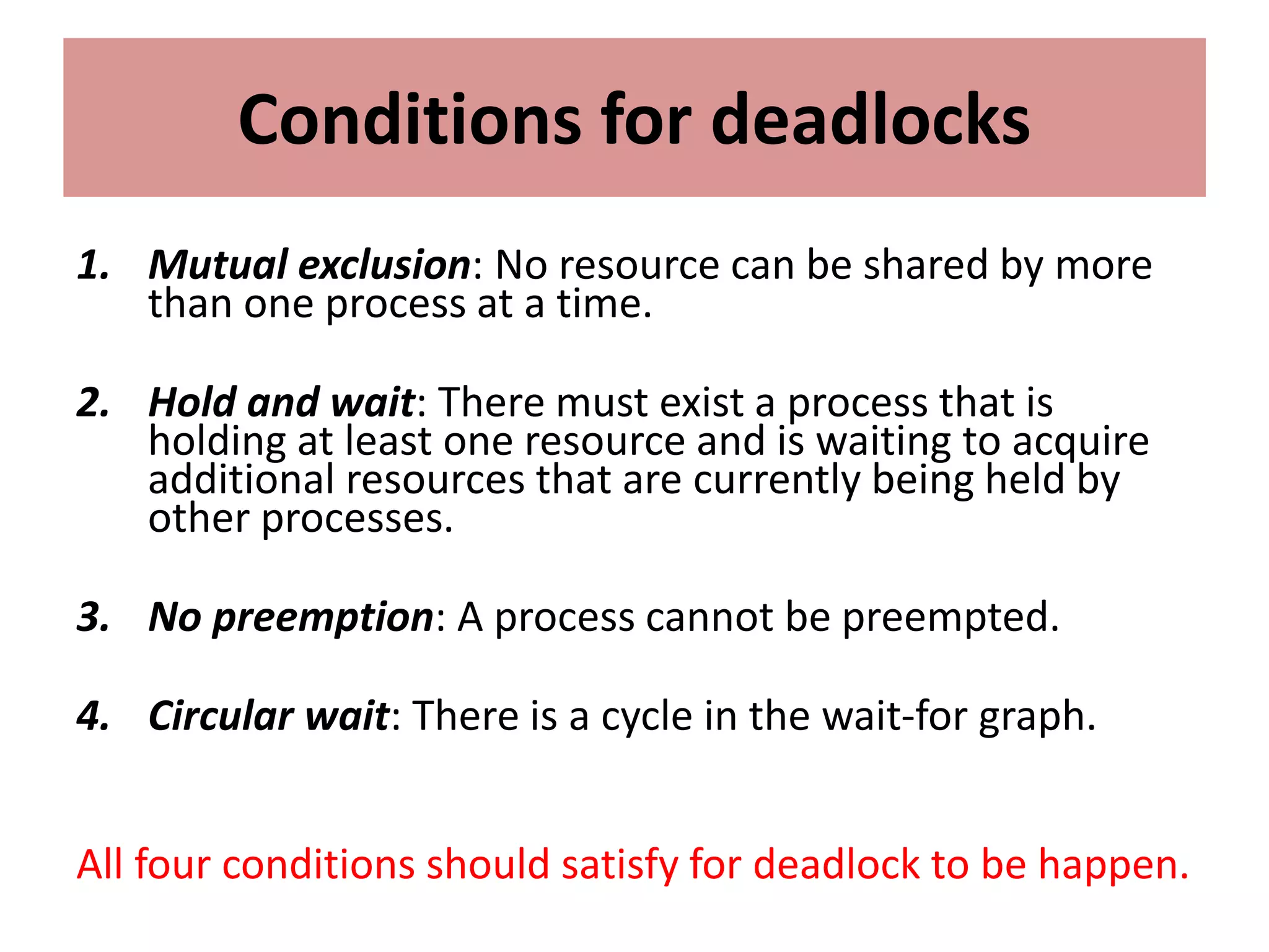
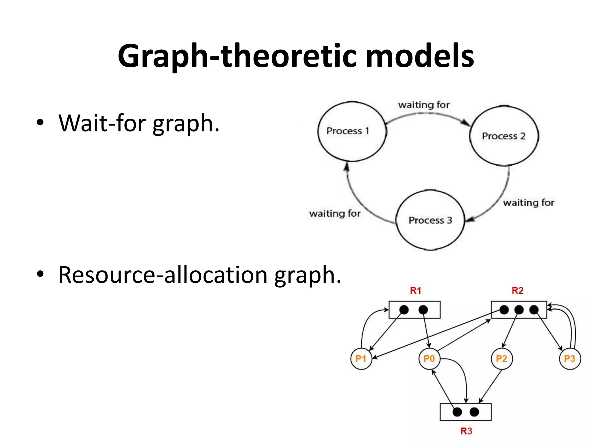
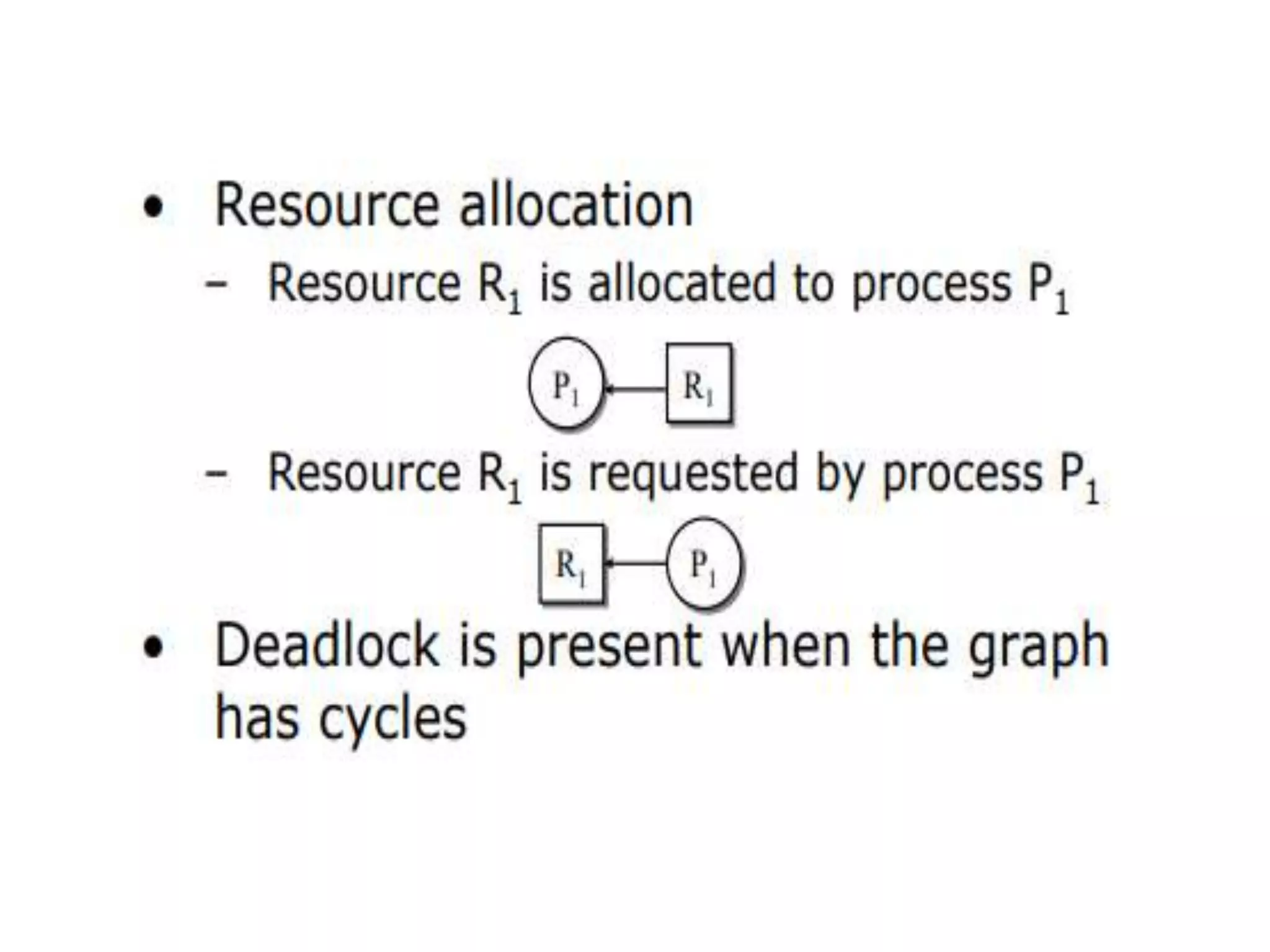
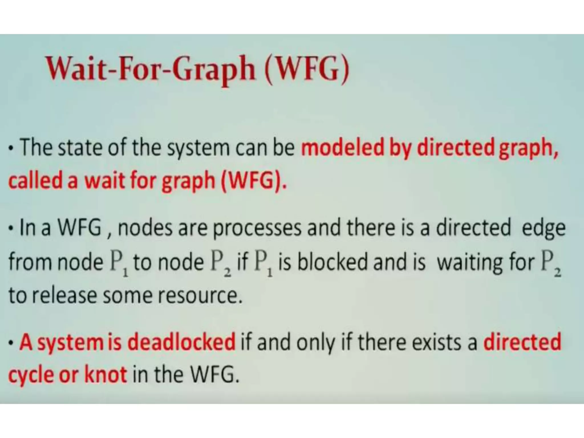
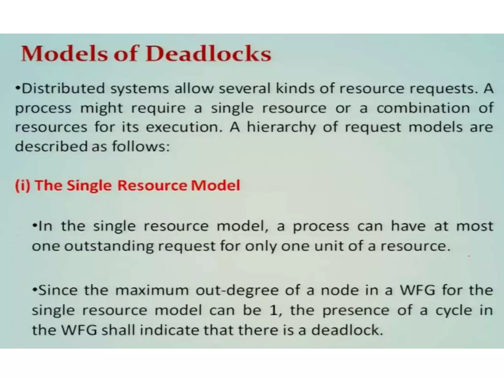
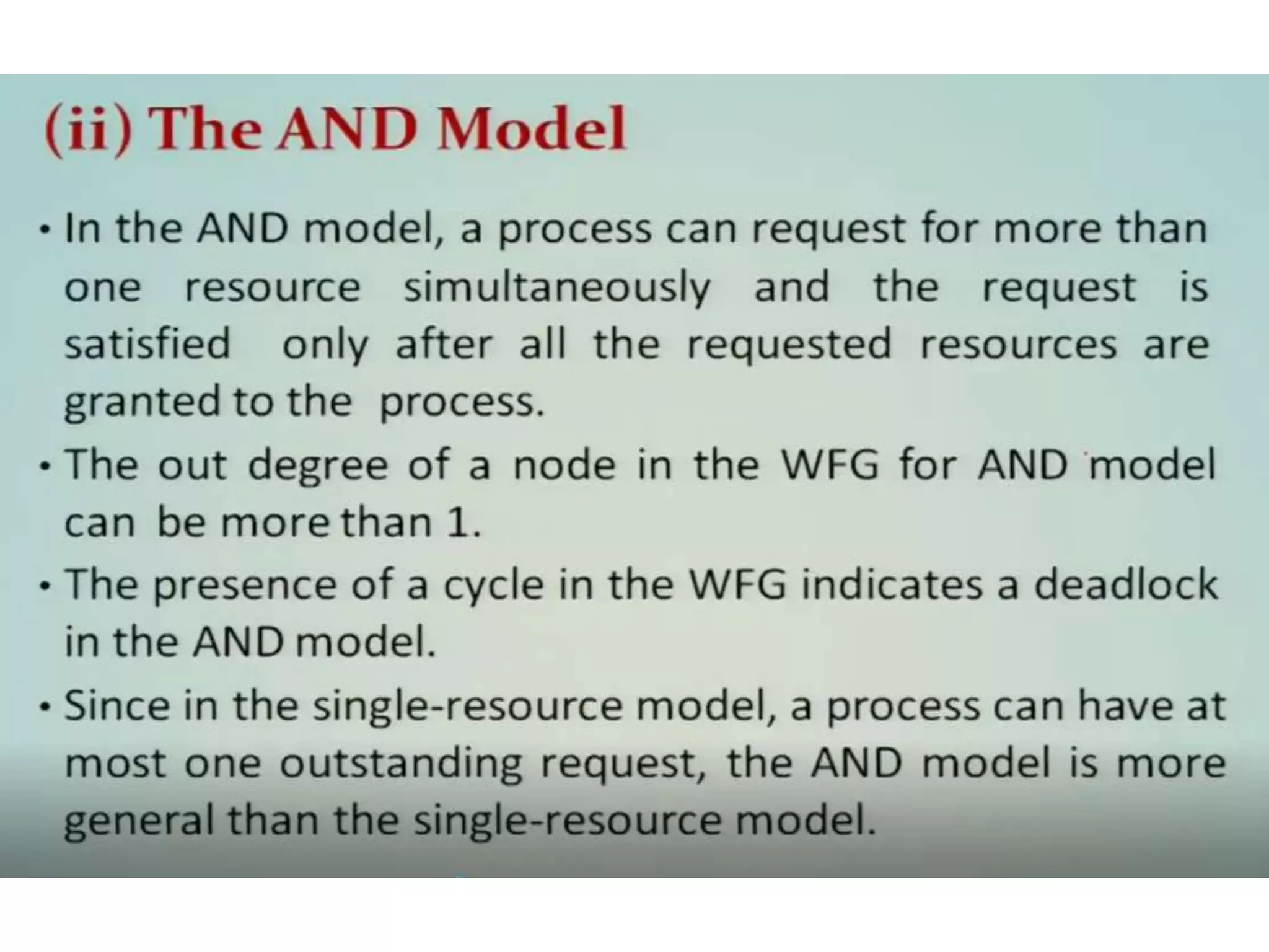
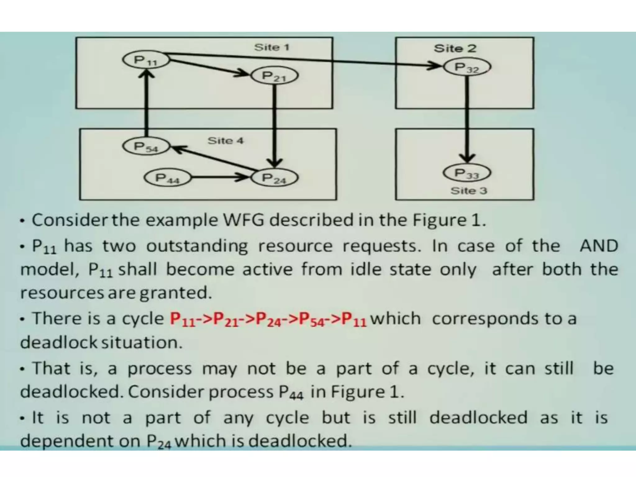
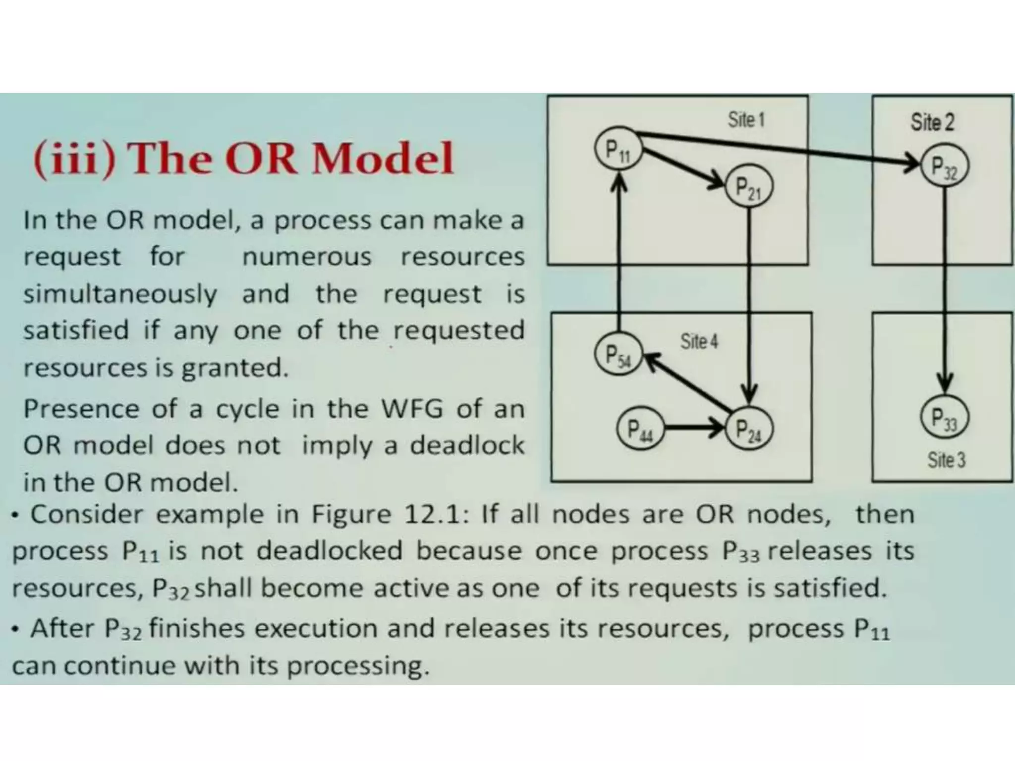
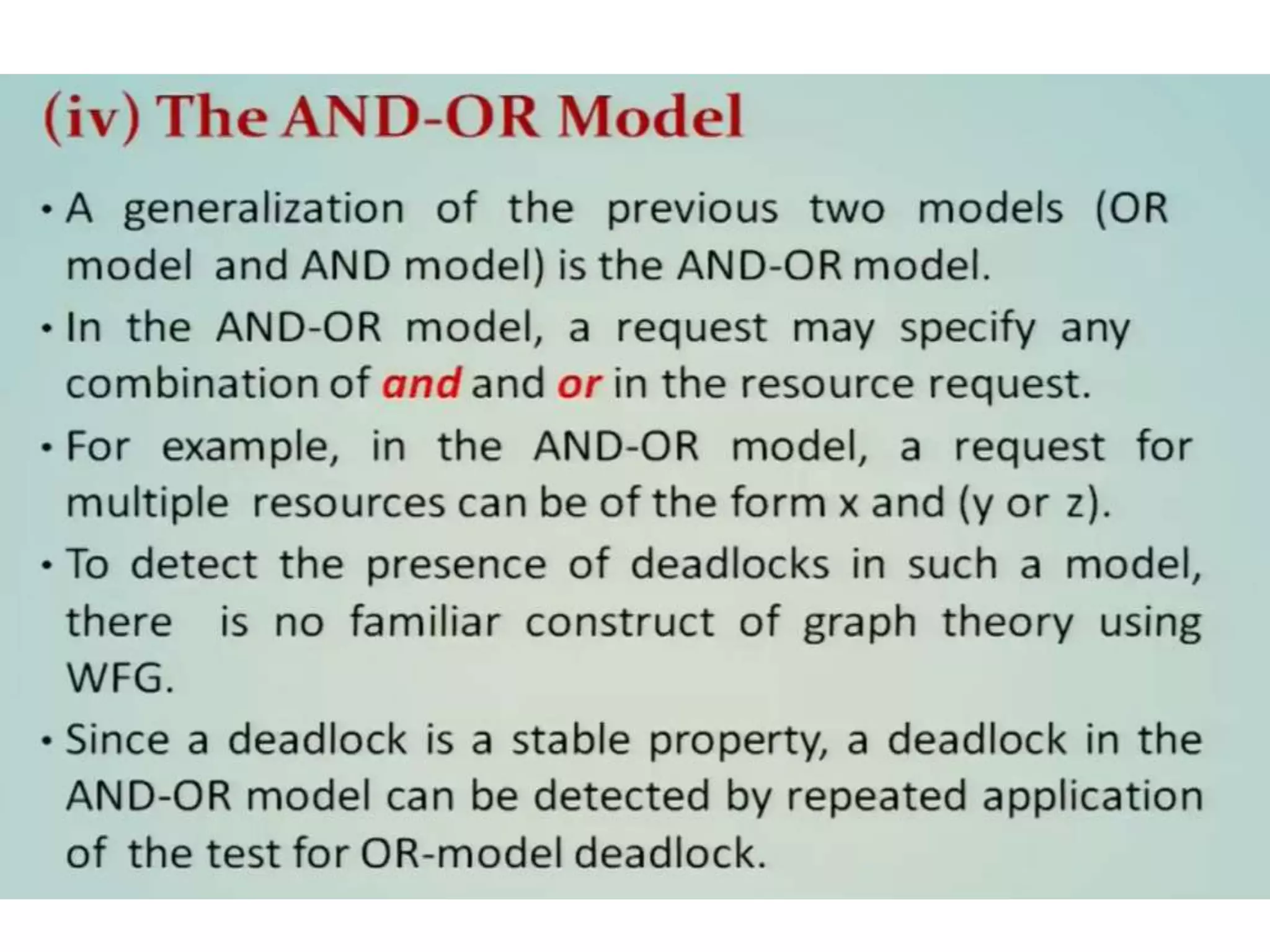
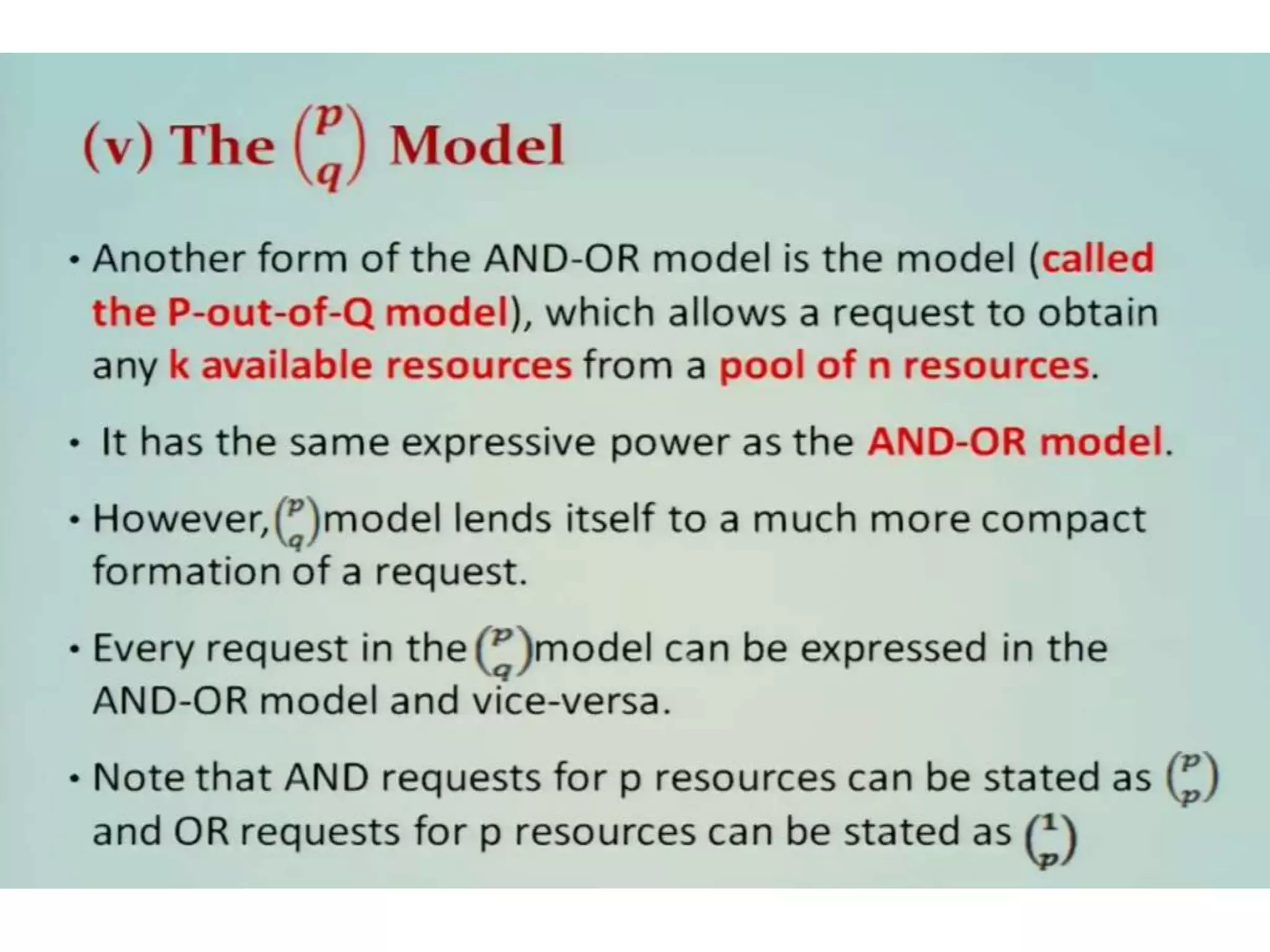
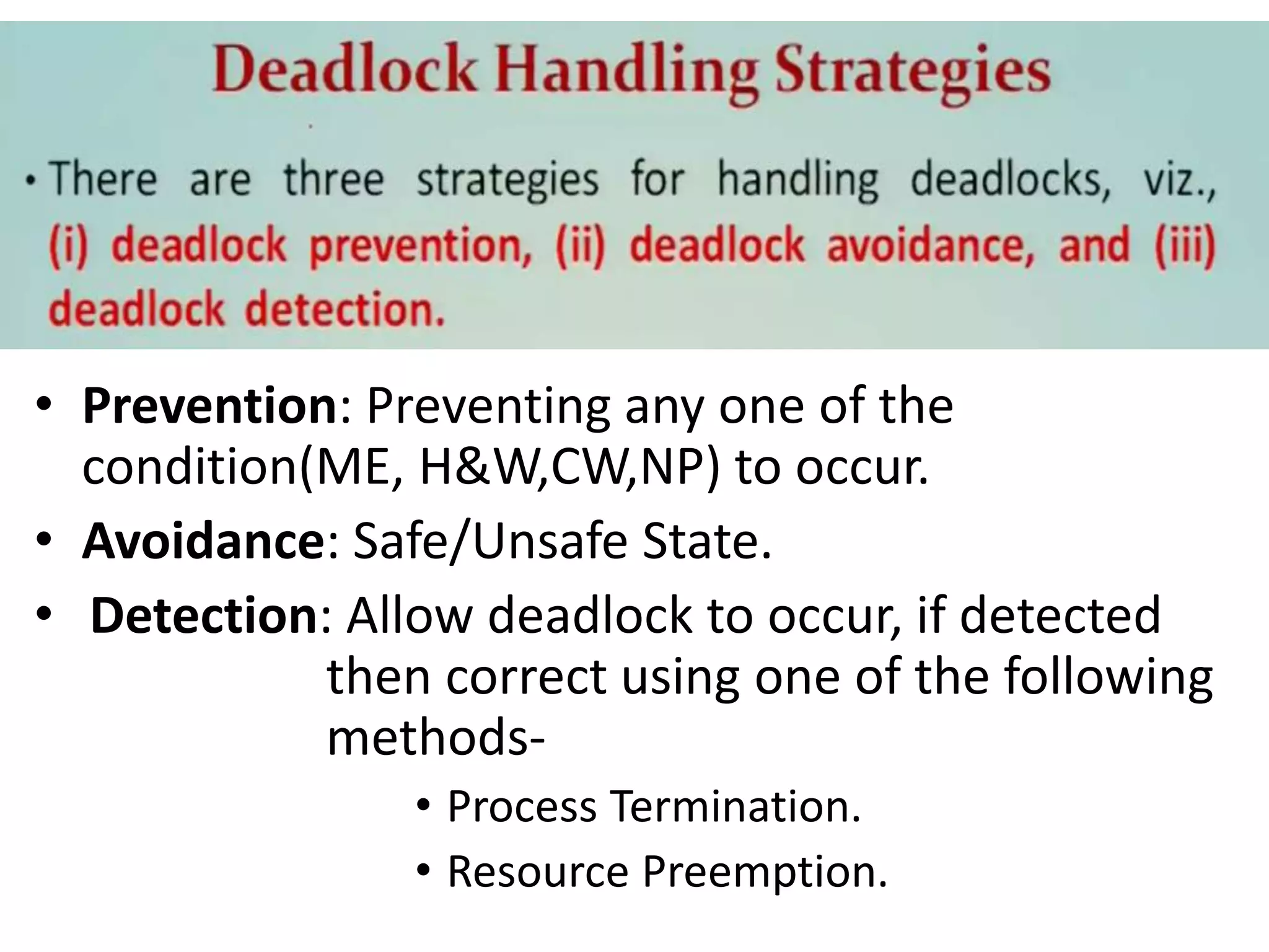
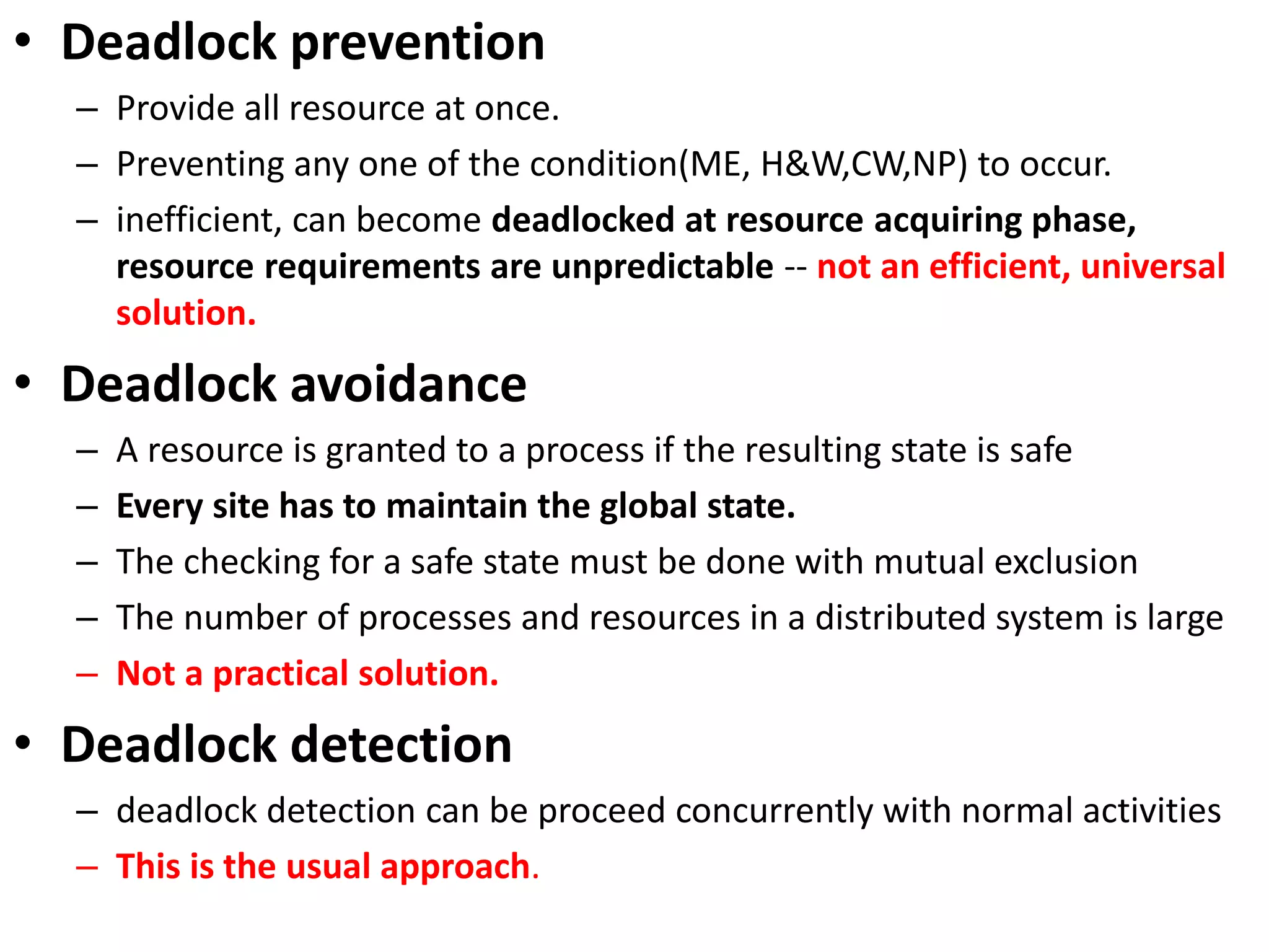
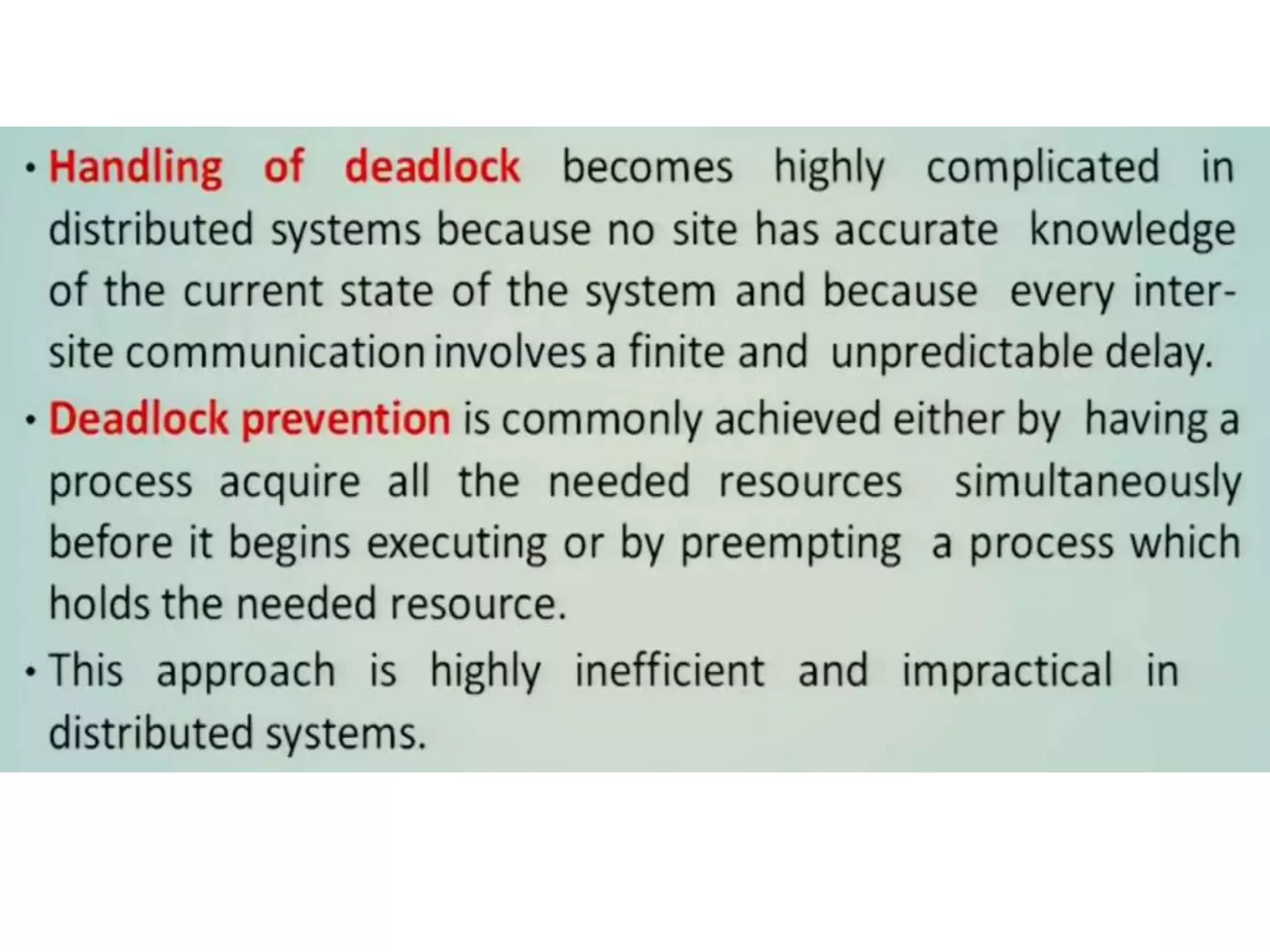
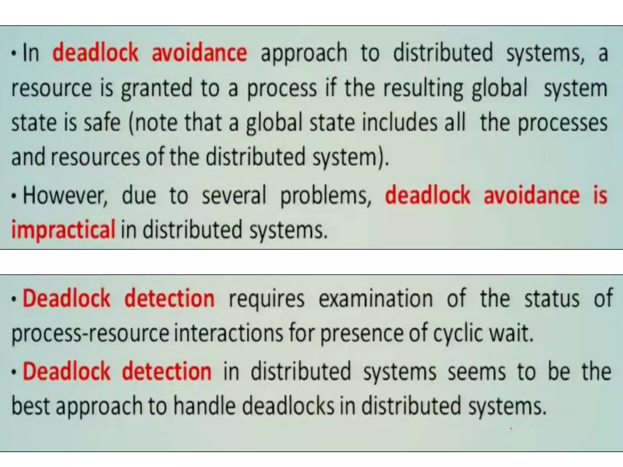
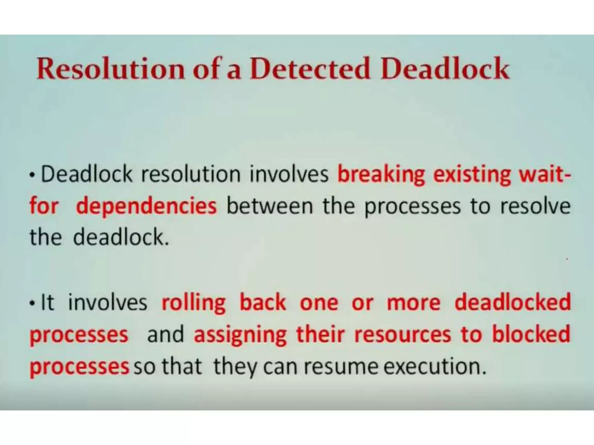
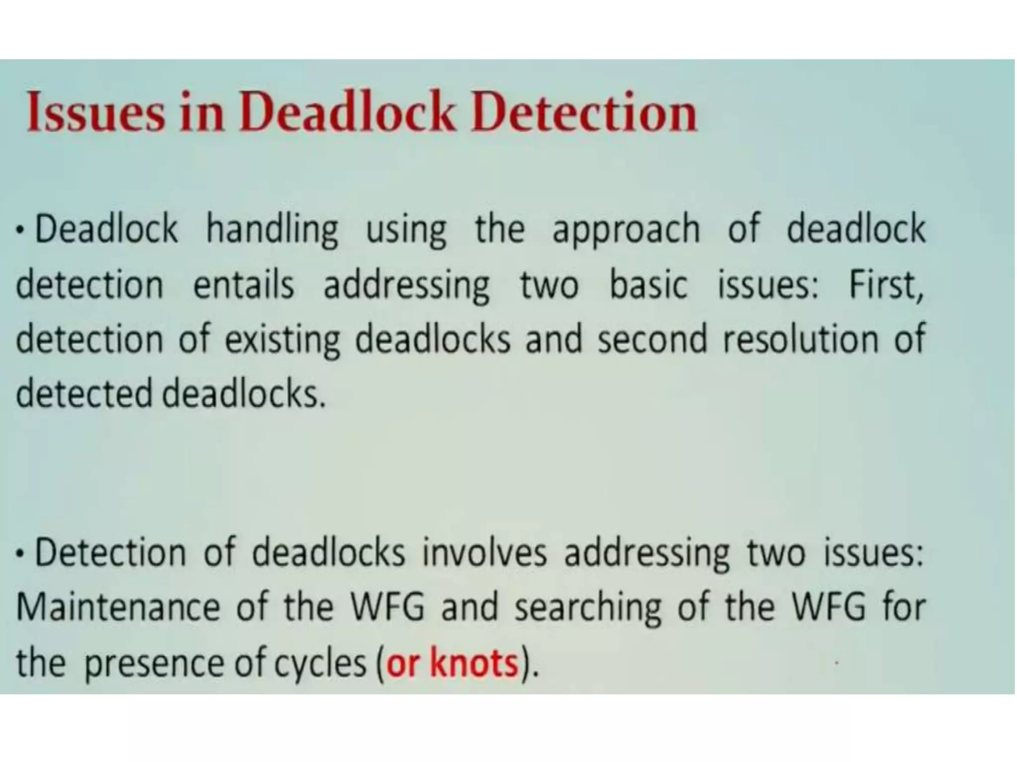

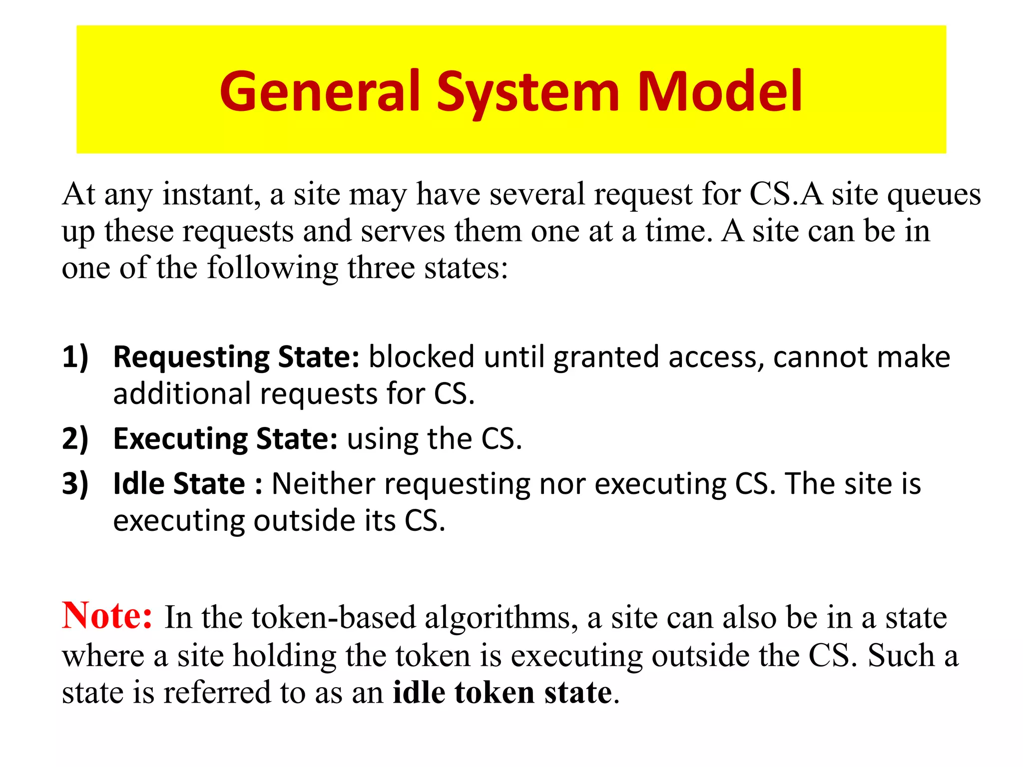
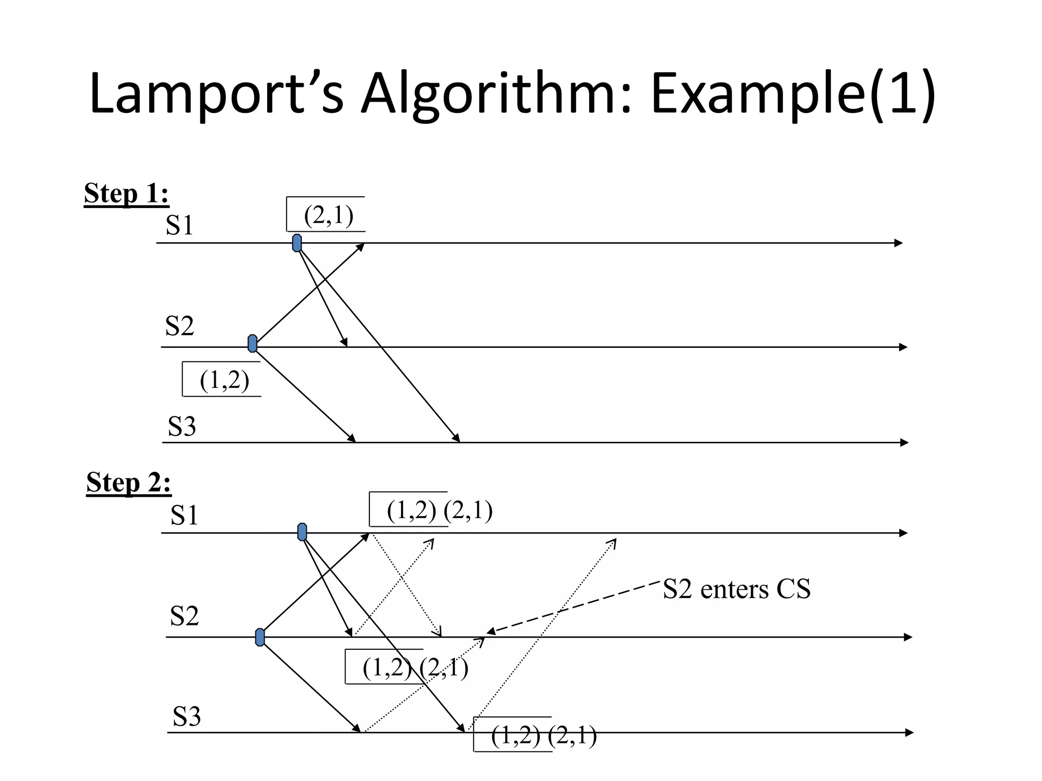
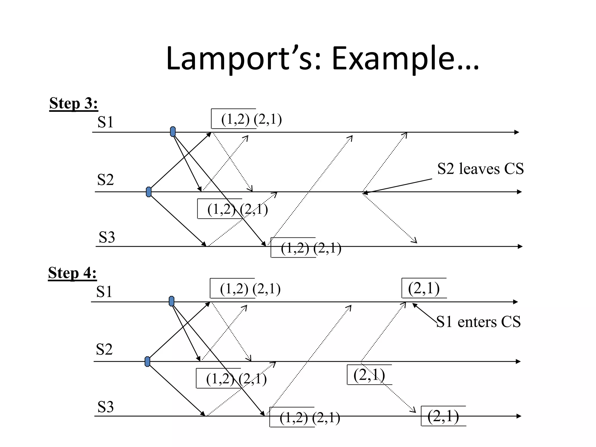
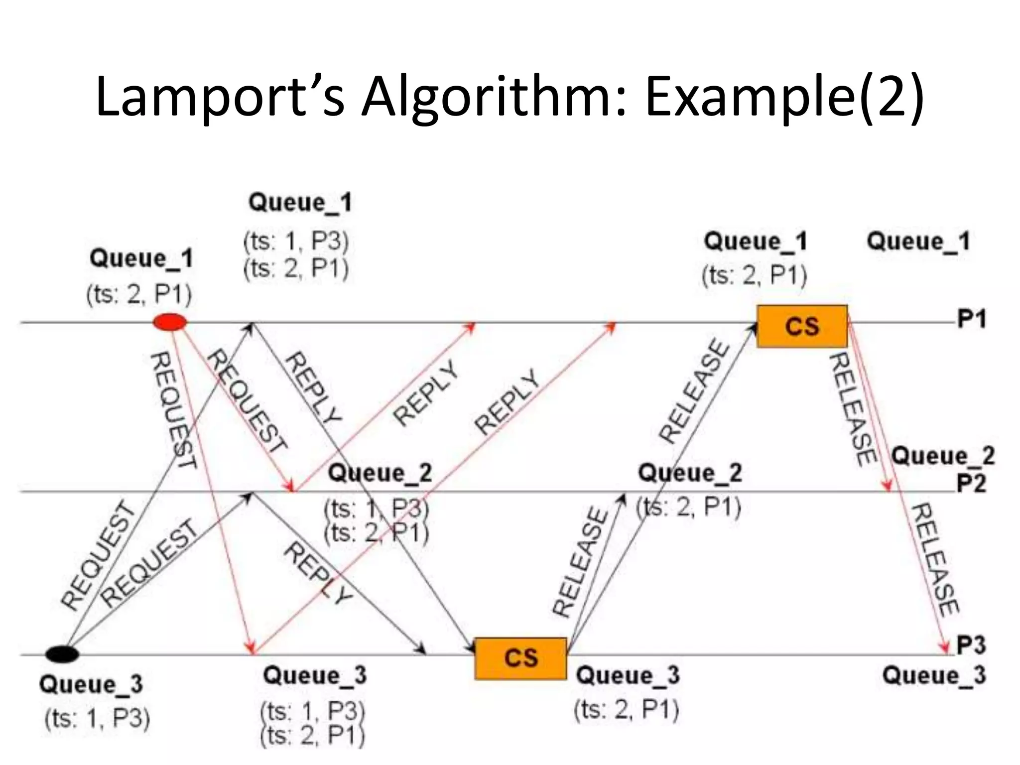
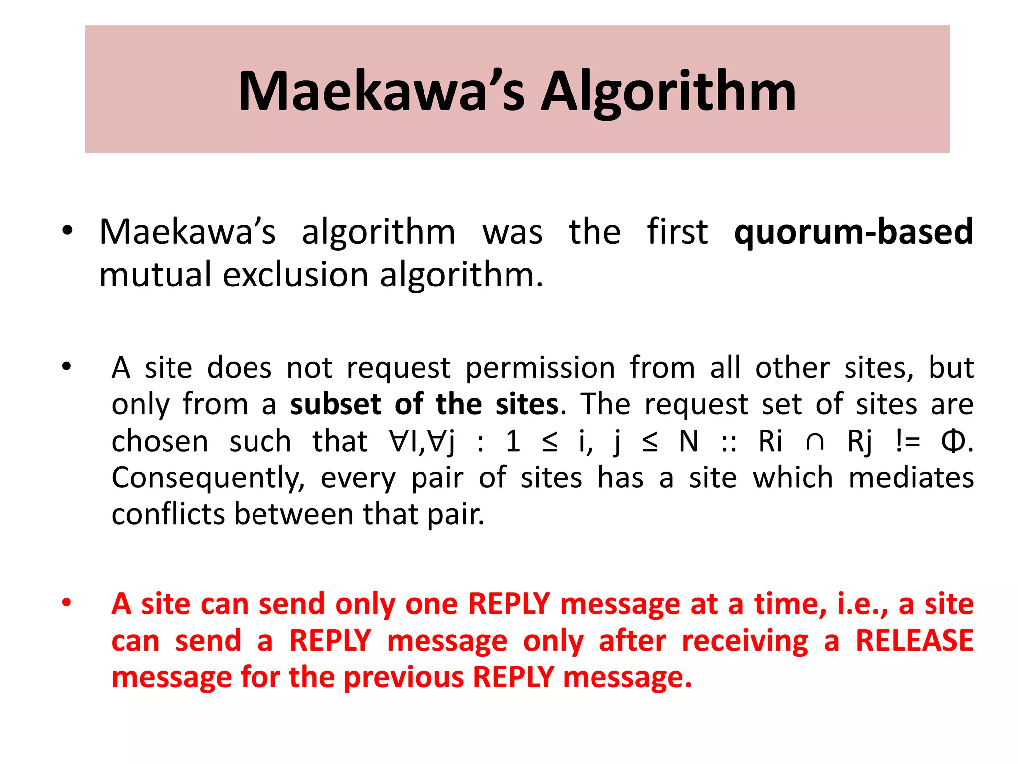
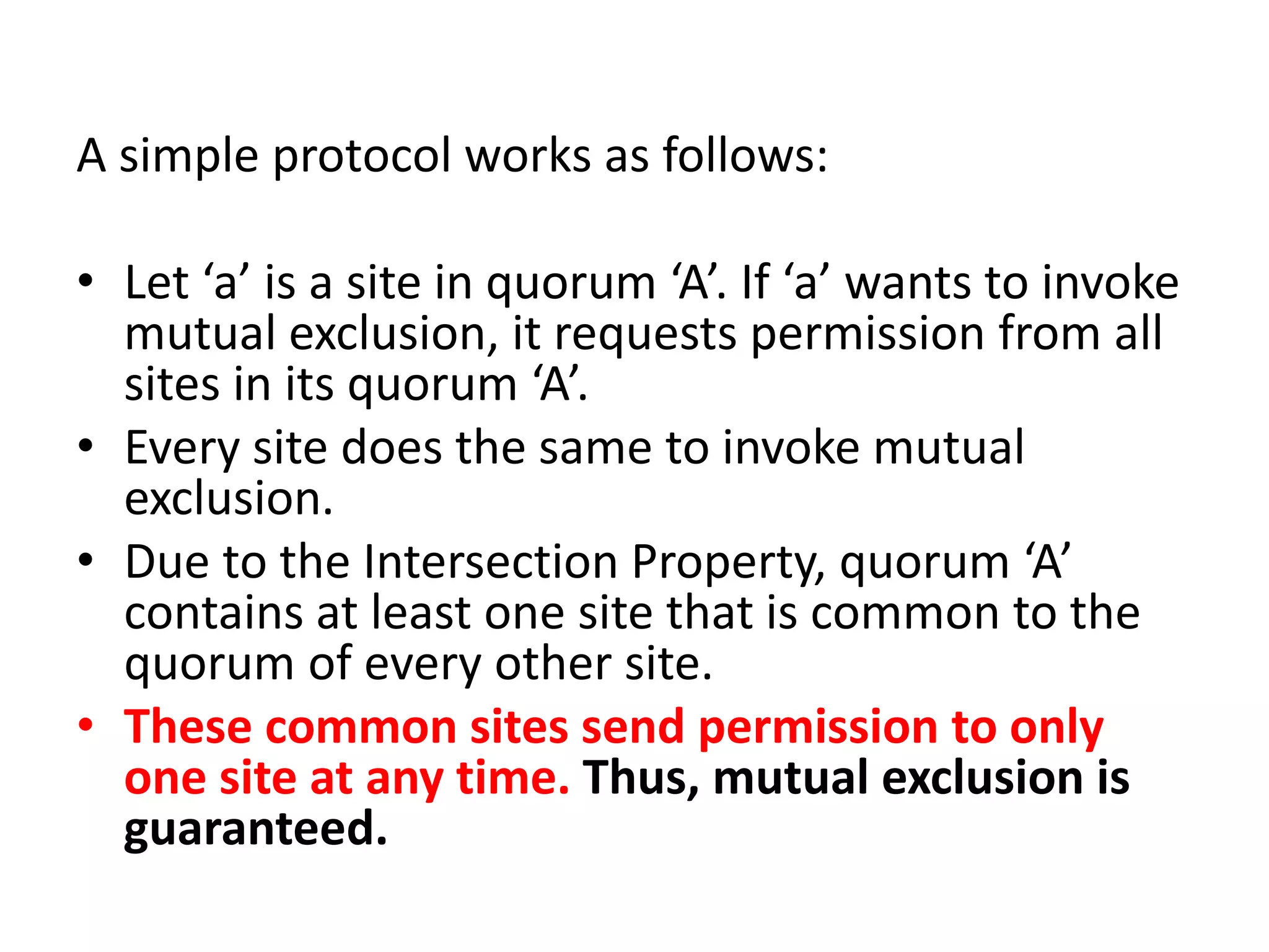
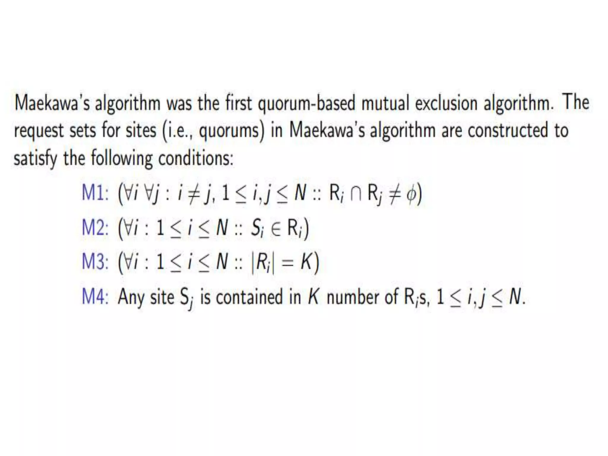
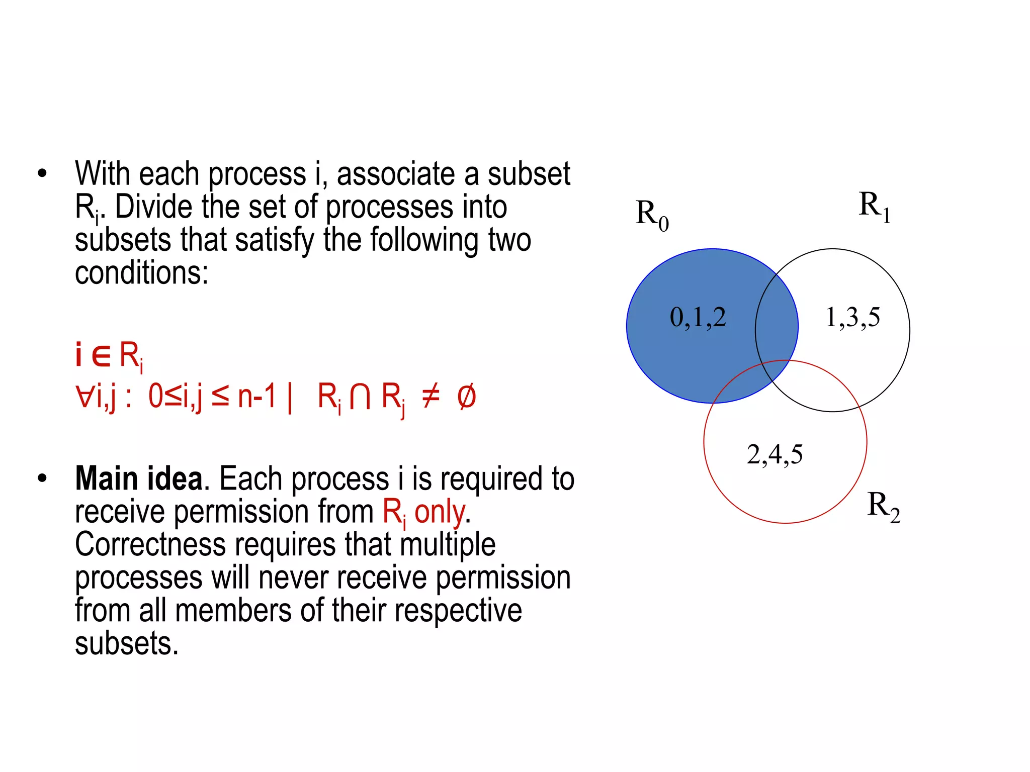
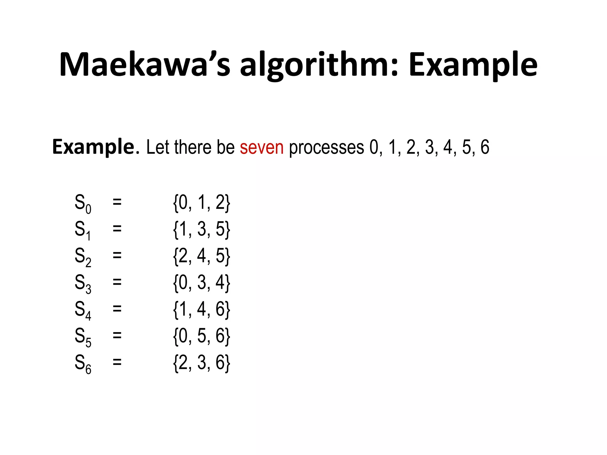
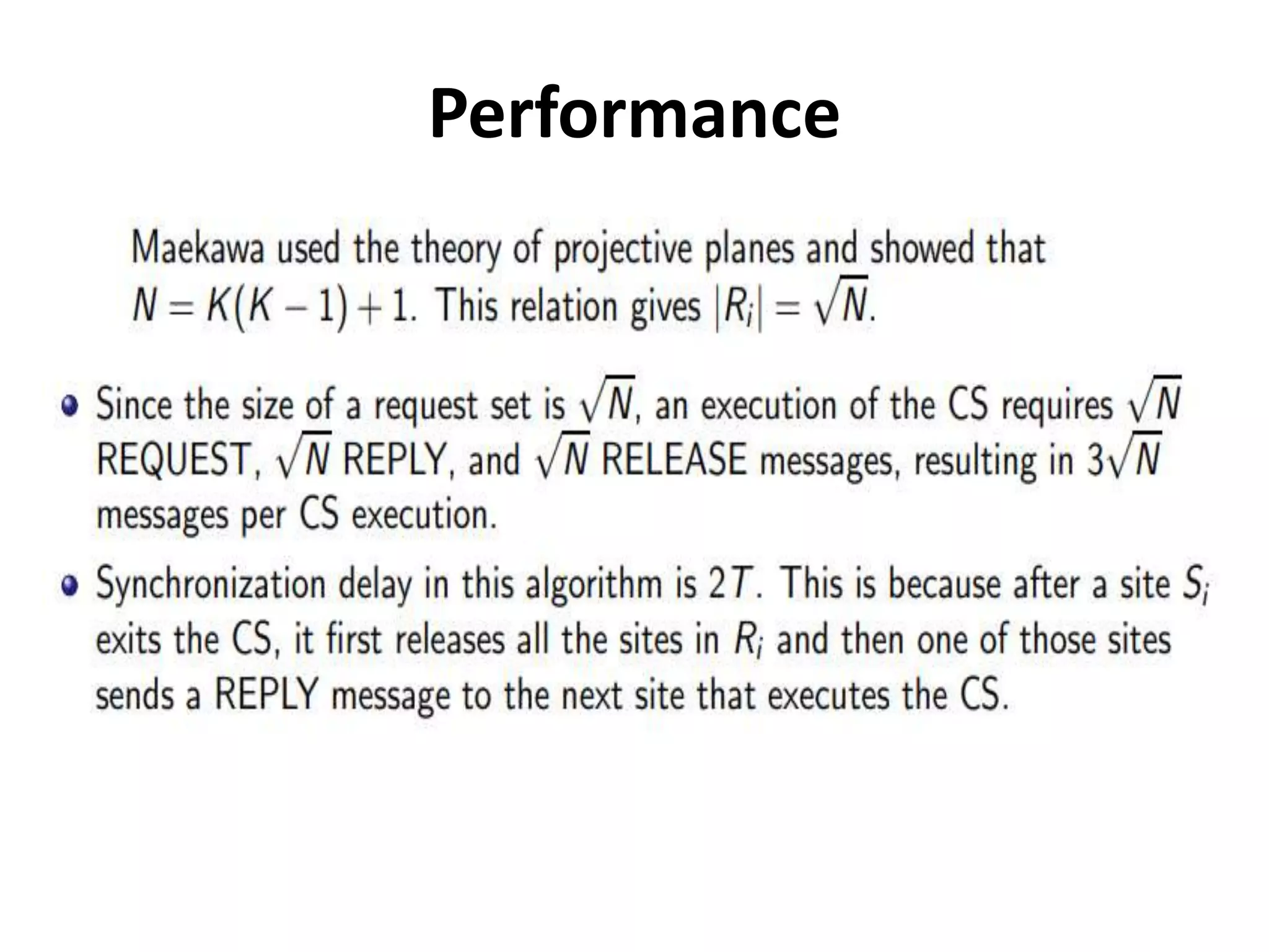
This document summarizes key concepts related to distributed mutual exclusion and distributed deadlock detection. It discusses classification of distributed mutual exclusion algorithms into token-based and non-token-based approaches. For distributed mutual exclusion, it describes Lamport's algorithm, Ricart-Agrawala algorithm, Maekawa's quorum-based algorithm, and Suzuki-Kasami's token-based broadcast algorithm. It also discusses requirements for mutual exclusion such as freedom from deadlock and starvation. For distributed deadlock detection, it mentions the system model and types of deadlocks as well as approaches for prevention, avoidance, detection, and resolution of deadlocks.