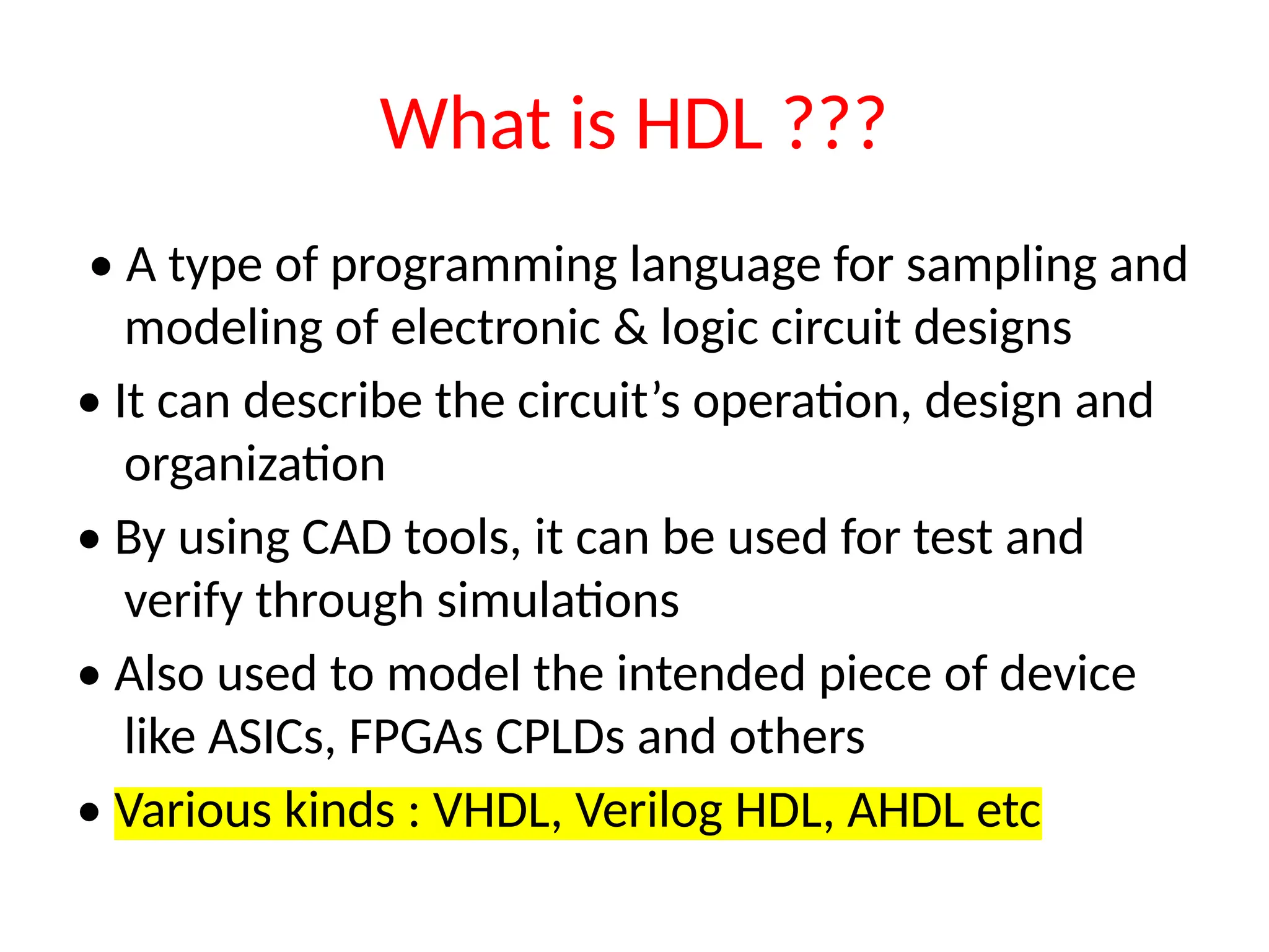
What is HDL??? • A type of programming language for sampling and modeling of electronic & logic circuit designs • It can describe the circuit’s operation, design and organization • By using CAD tools, it can be used for test and verify through simulations • Also used to model the intended piece of device like ASICs, FPGAs CPLDs and others • Various kinds : VHDL, Verilog HDL, AHDL etc
3.
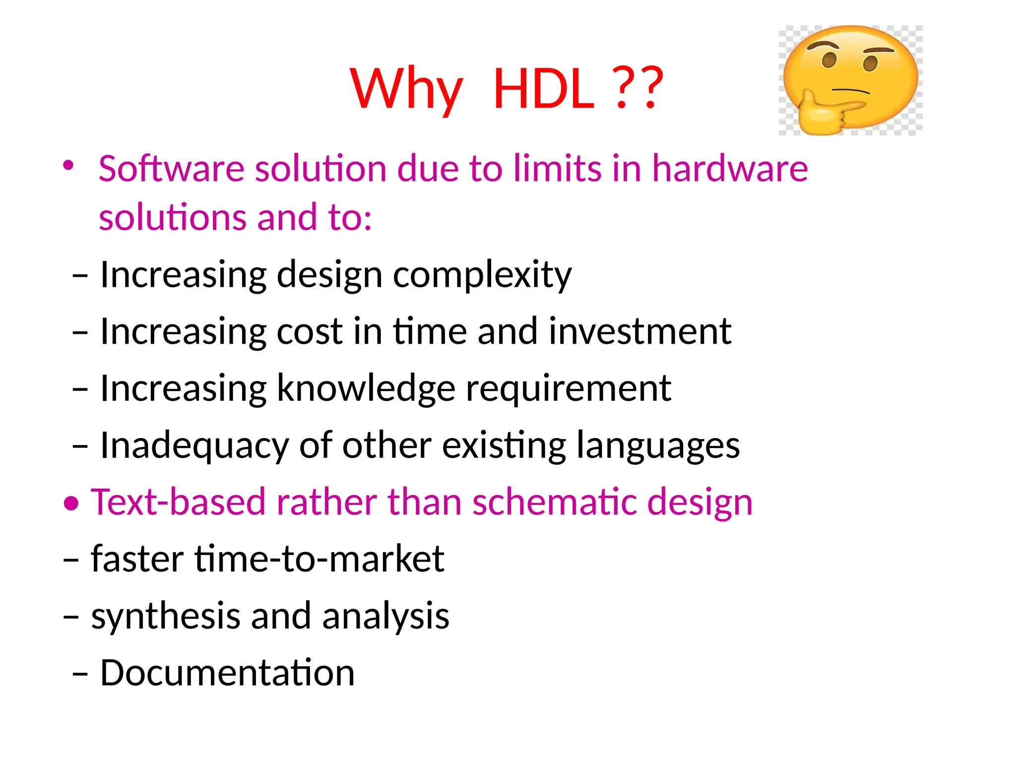
Why HDL ?? •Software solution due to limits in hardware solutions and to: – Increasing design complexity – Increasing cost in time and investment – Increasing knowledge requirement – Inadequacy of other existing languages • Text-based rather than schematic design – faster time-to-market – synthesis and analysis – Documentation
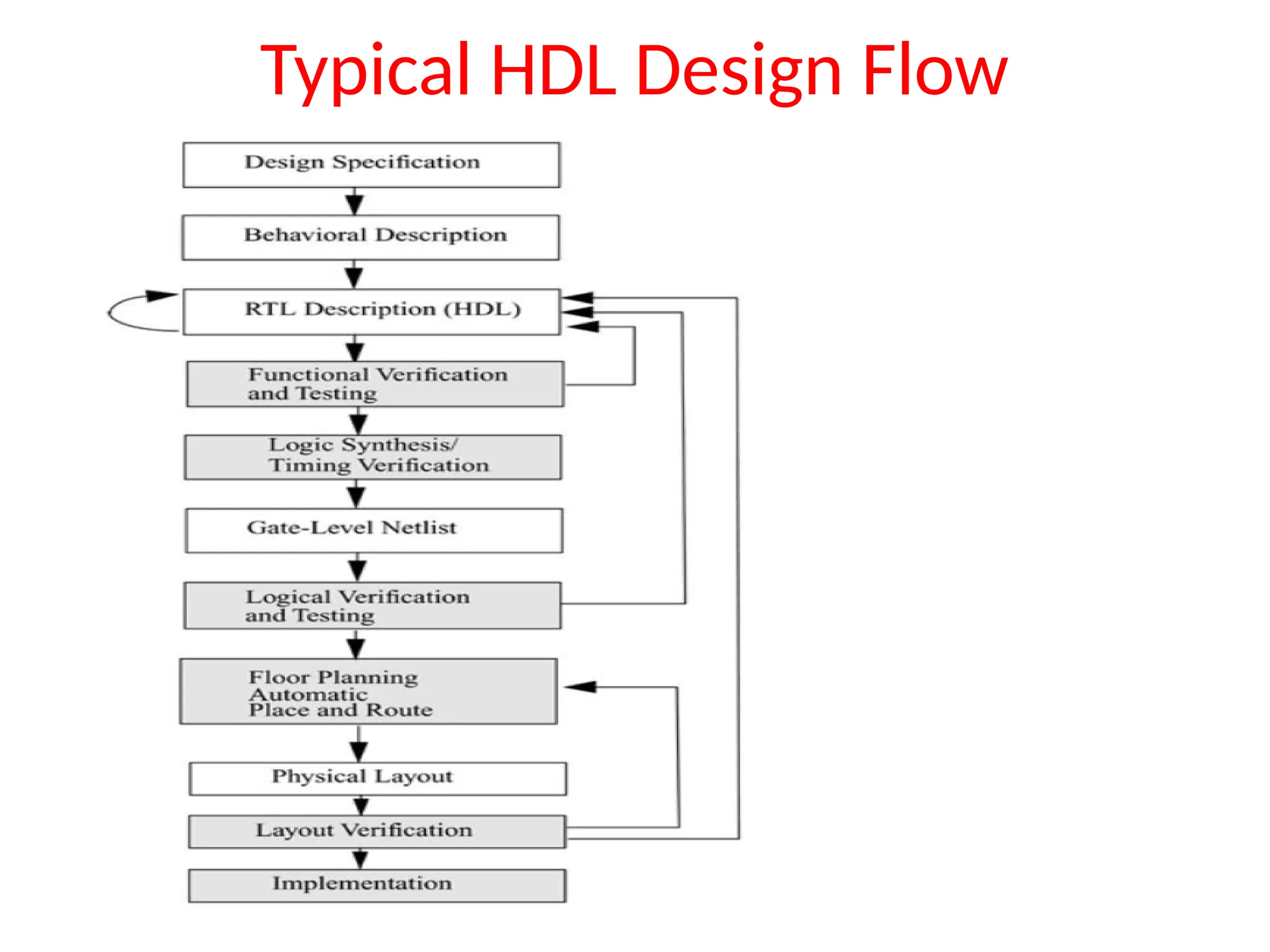
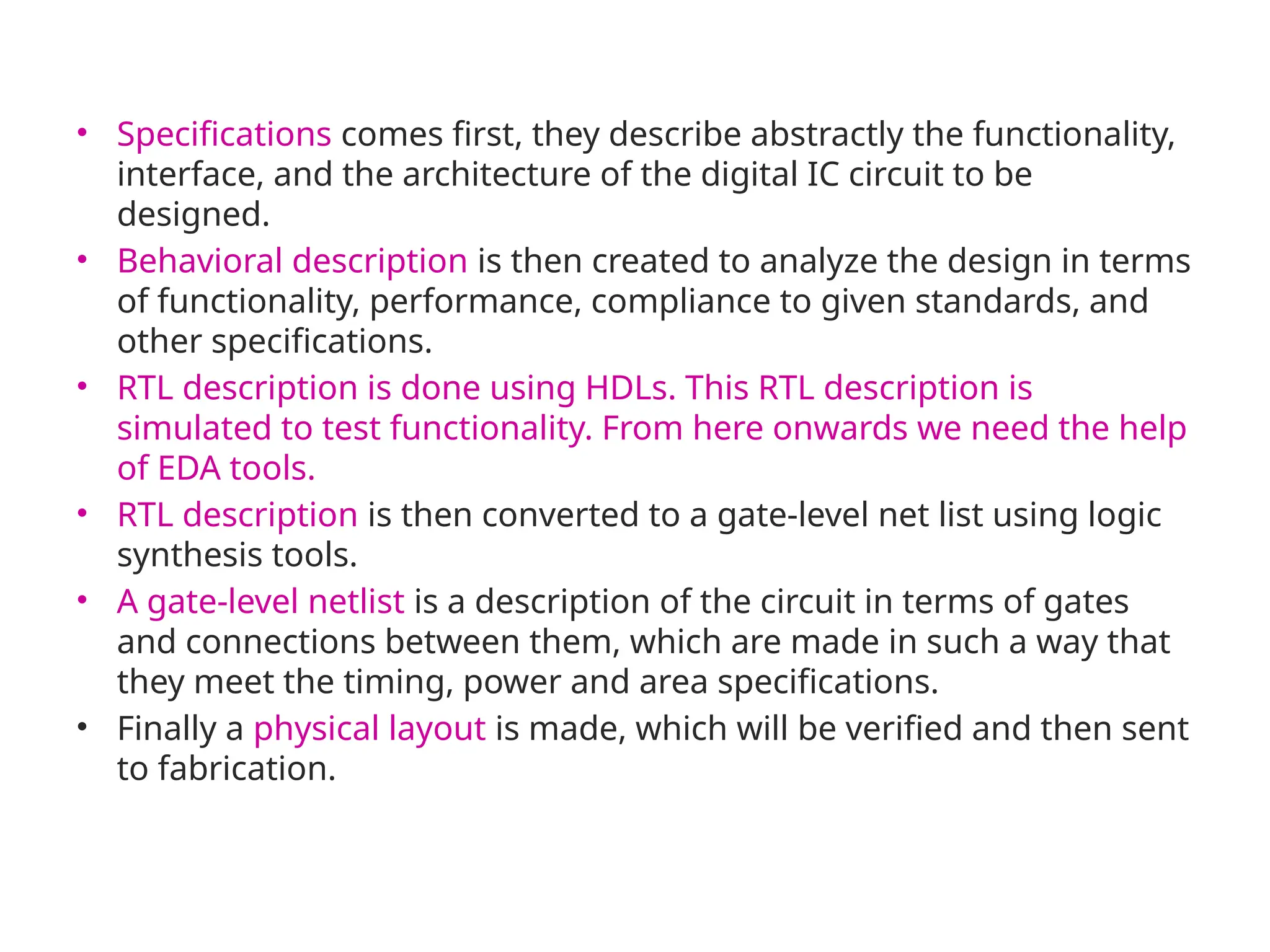
• Specifications comesfirst, they describe abstractly the functionality, interface, and the architecture of the digital IC circuit to be designed. • Behavioral description is then created to analyze the design in terms of functionality, performance, compliance to given standards, and other specifications. • RTL description is done using HDLs. This RTL description is simulated to test functionality. From here onwards we need the help of EDA tools. • RTL description is then converted to a gate-level net list using logic synthesis tools. • A gate-level netlist is a description of the circuit in terms of gates and connections between them, which are made in such a way that they meet the timing, power and area specifications. • Finally a physical layout is made, which will be verified and then sent to fabrication.
6.
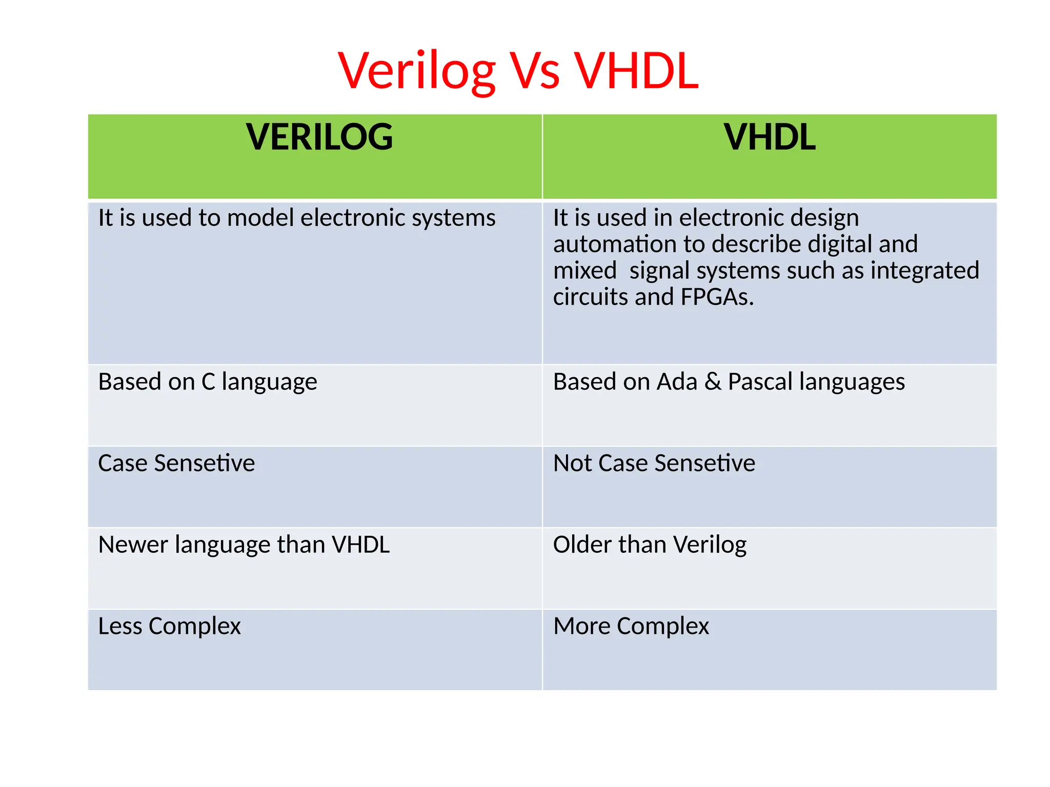
Verilog Vs VHDL VERILOGVHDL It is used to model electronic systems It is used in electronic design automation to describe digital and mixed signal systems such as integrated circuits and FPGAs. Based on C language Based on Ada & Pascal languages Case Sensetive Not Case Sensetive Newer language than VHDL Older than Verilog Less Complex More Complex
7.
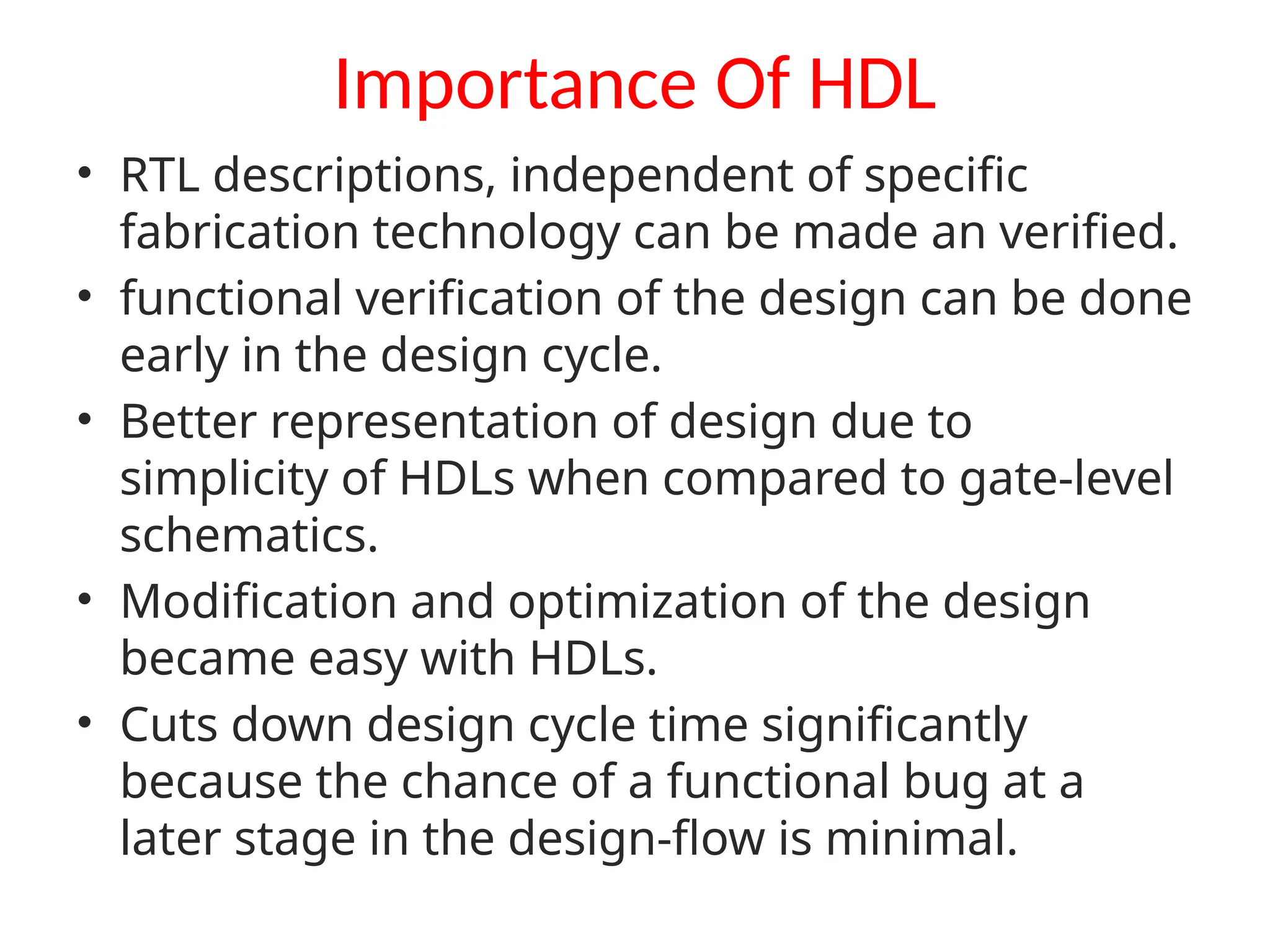
Importance Of HDL •RTL descriptions, independent of specific fabrication technology can be made an verified. • functional verification of the design can be done early in the design cycle. • Better representation of design due to simplicity of HDLs when compared to gate-level schematics. • Modification and optimization of the design became easy with HDLs. • Cuts down design cycle time significantly because the chance of a functional bug at a later stage in the design-flow is minimal.
8.
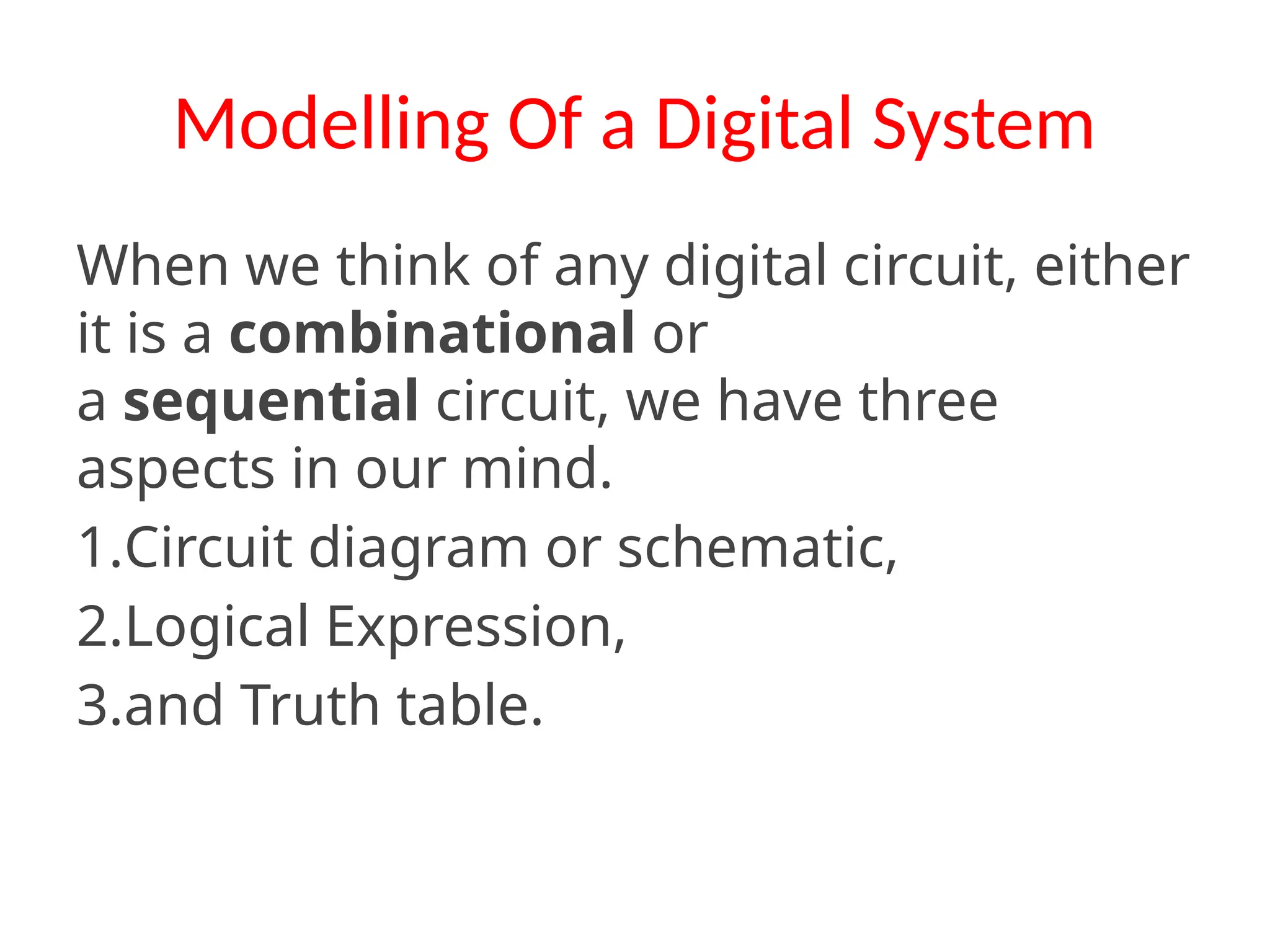
Modelling Of aDigital System When we think of any digital circuit, either it is a combinational or a sequential circuit, we have three aspects in our mind. 1.Circuit diagram or schematic, 2.Logical Expression, 3.and Truth table.
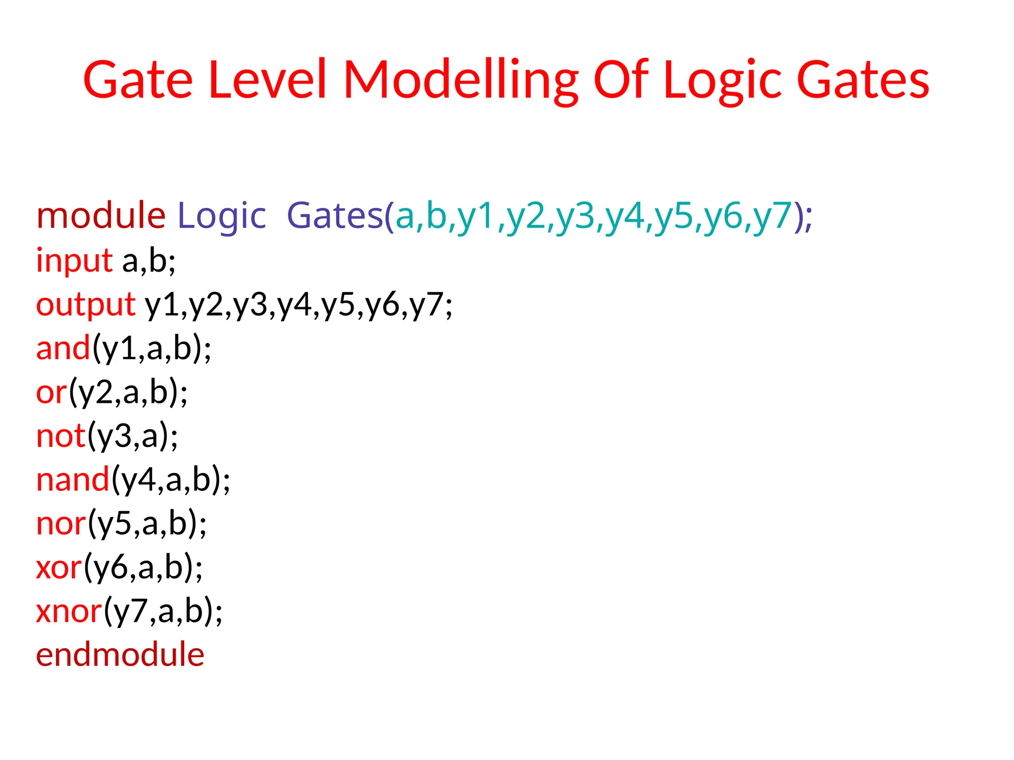
Structural Modelling: • Ituses Module Instantiation • Describes the structure of a circuit with modules at different levels. Gate Level Modelling: • It uses Primitive gates, and predefined modules. • Lowest level abstraction • but is easy and guaranteed for machine compiling and logical synthesis.
11.
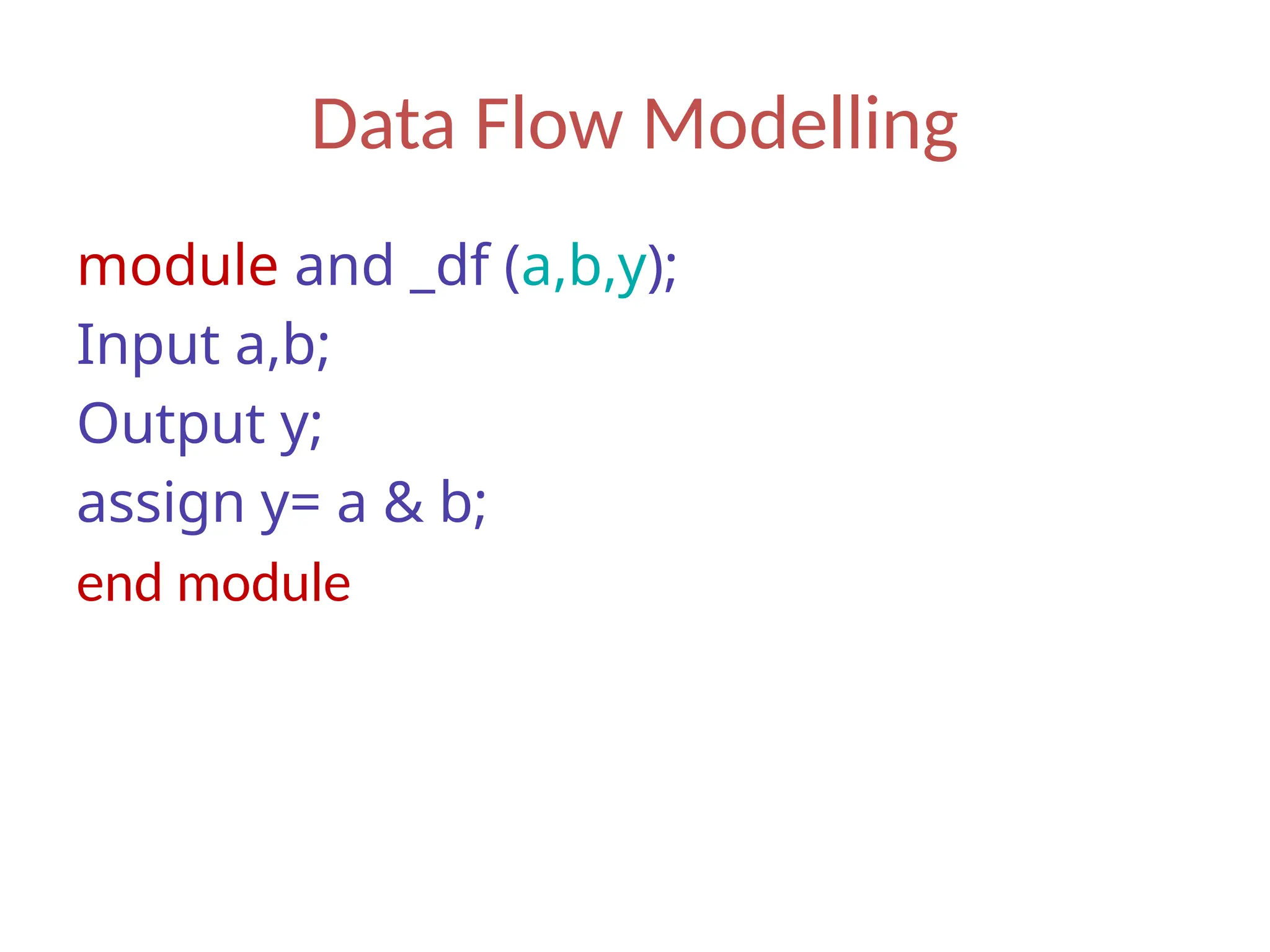
Data Flow Modelling •It is completely done by the logical expression of the digital circuit • logical and arithmetic operators in Verilog, are used to create logical expressions of the digital circuit. • This is a medium level abstraction • This type of modelling along with structural modelling is Highly Recommended in ASIC design.
12.
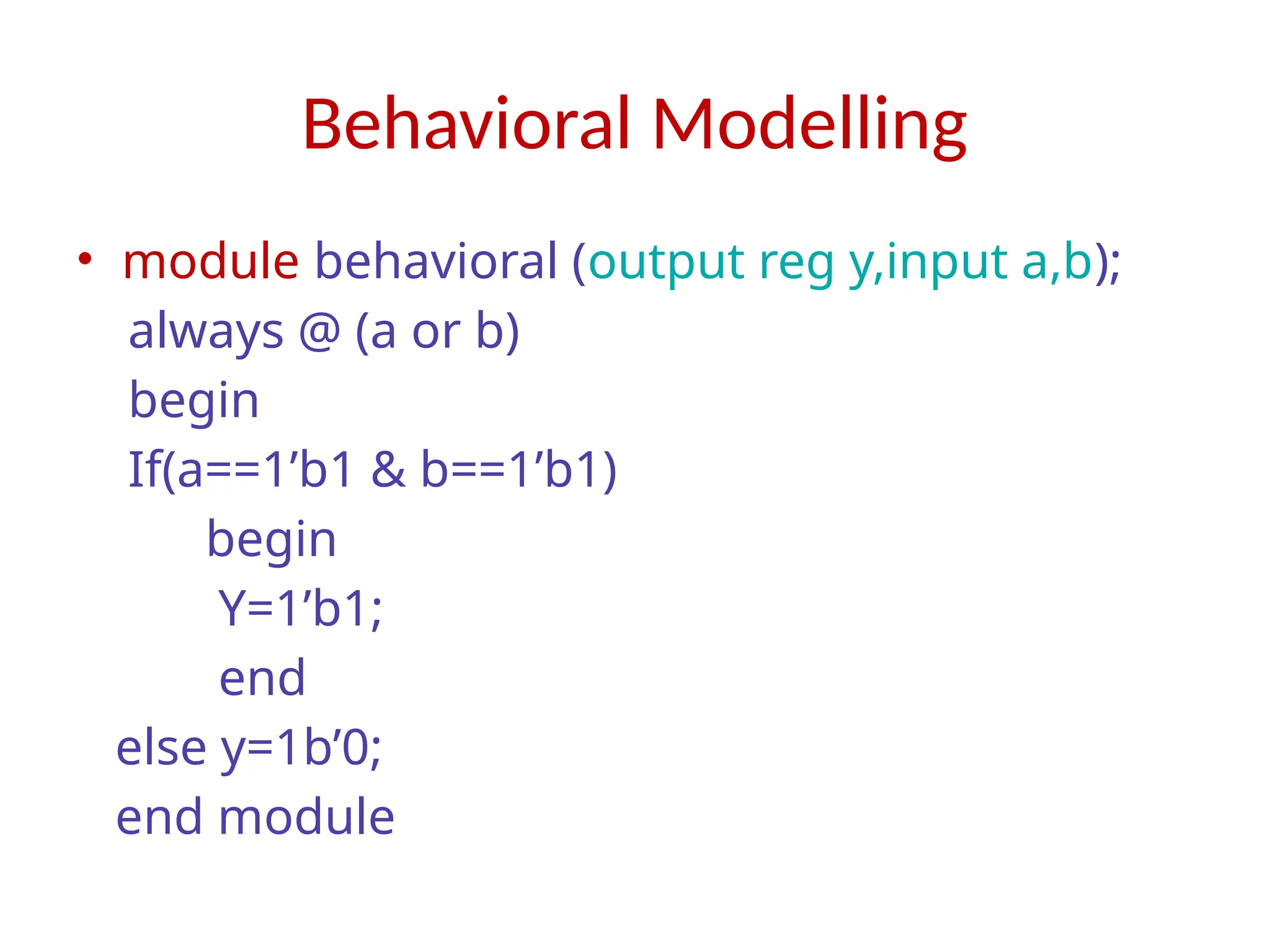
Behavioral Modelling • Completelydepends on the truth table or behaviour of the circuit • we can design hardware without even knowing the components present in it, because it doesn’t care. • This is the highest level abstraction. • This modelling is recommended for FPGA prototyping and other Reconfigurable devices.
Behavioral Modelling • modulebehavioral (output reg y,input a,b); always @ (a or b) begin If(a==1’b1 & b==1’b1) begin Y=1’b1; end else y=1b’0; end module
16.
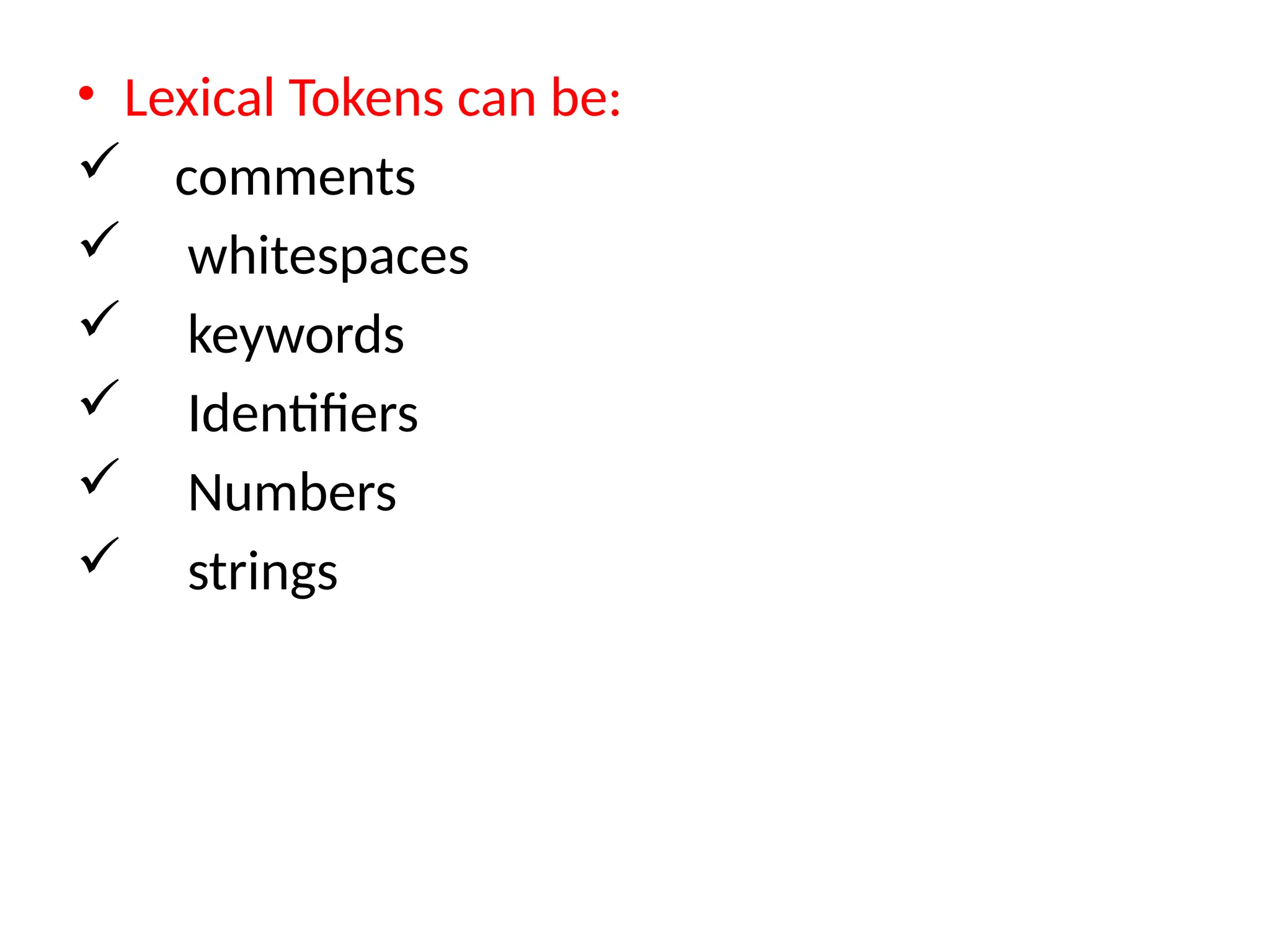
LEXICAL Conventions • “Lexicalelements” or “tokens” are used to construct statements, definitions,declarations and so on….,which are used to construct complete programs. • The basic lexical conventions used by Verilog HDL are similar to those in the C programming language. • Verilog contains a stream of tokens.
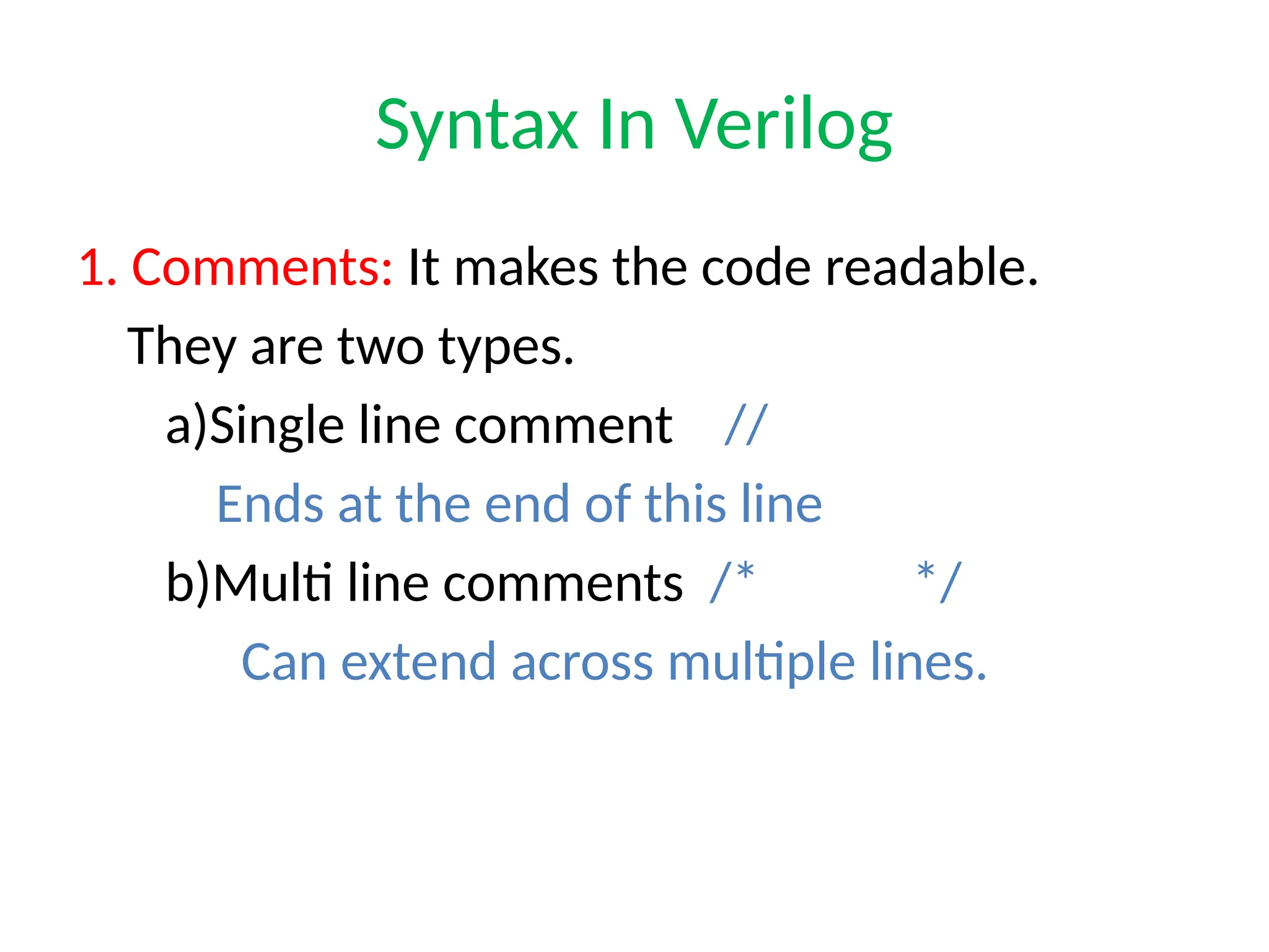
Syntax In Verilog 1.Comments: It makes the code readable. They are two types. a)Single line comment // Ends at the end of this line b)Multi line comments /* */ Can extend across multiple lines.
19.
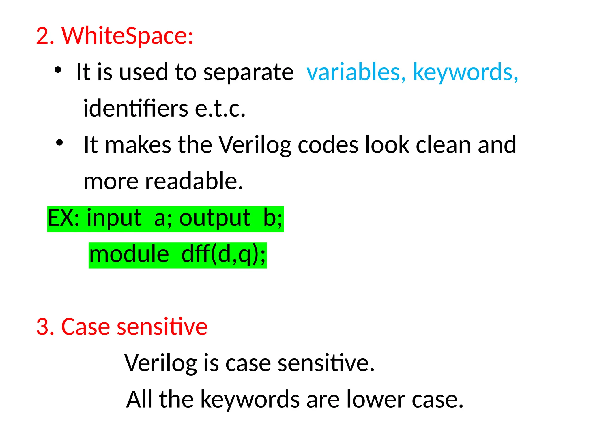
2. WhiteSpace: • Itis used to separate variables, keywords, identifiers e.t.c. • It makes the Verilog codes look clean and more readable. EX: input a; output b; module dff(d,q); 3. Case sensitive Verilog is case sensitive. All the keywords are lower case.
20.
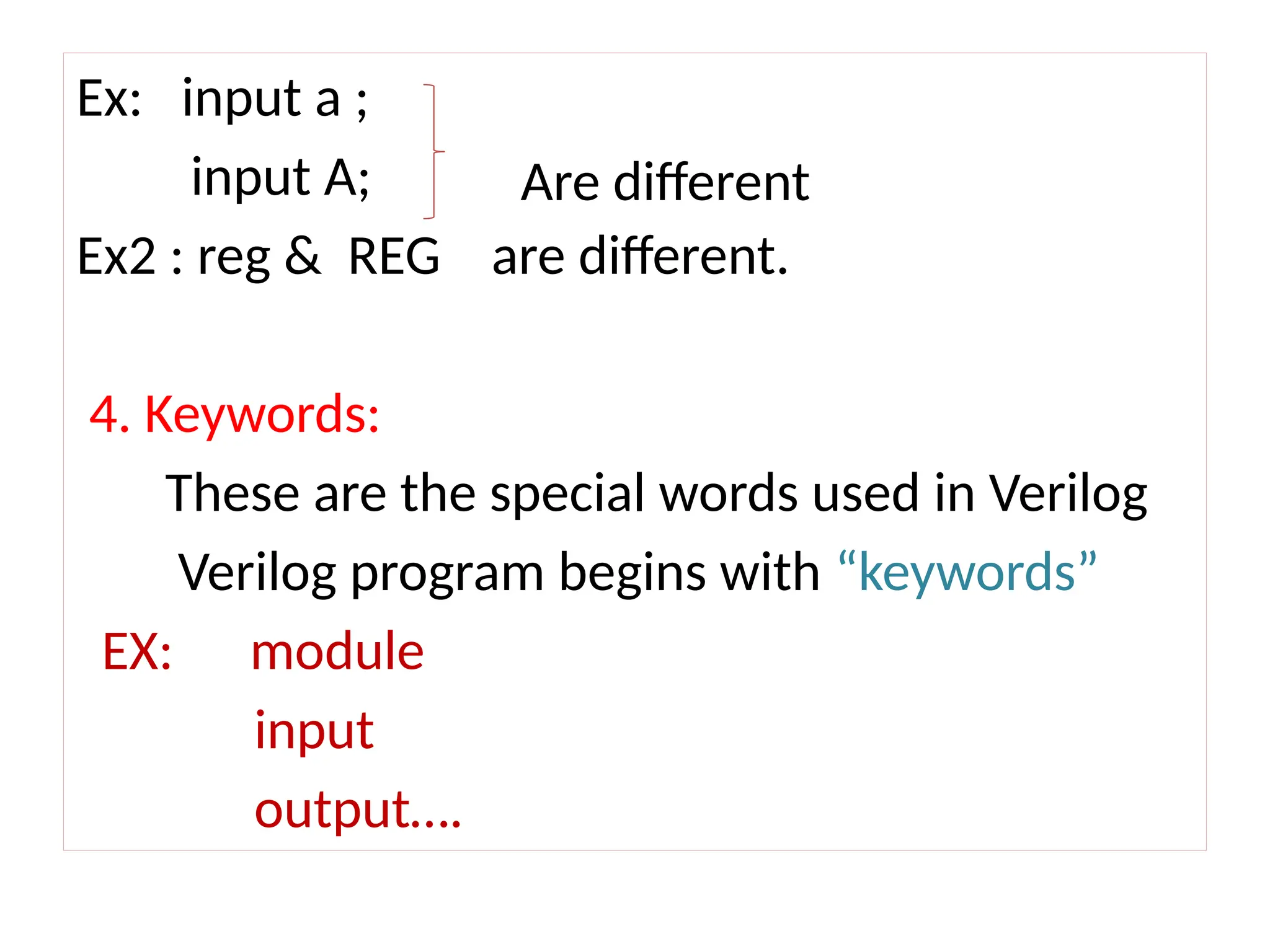
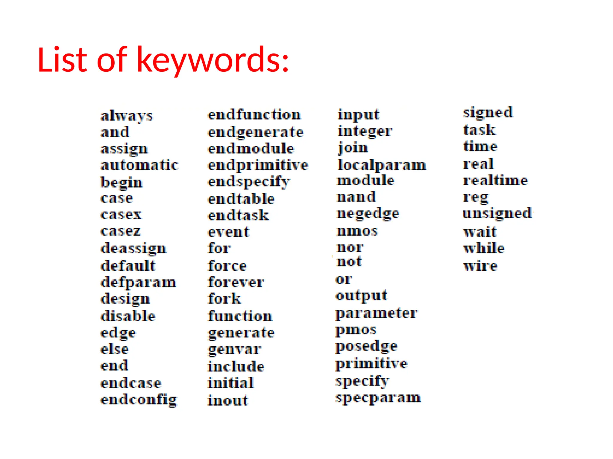
Ex: input a; input A; Ex2 : reg & REG are different. 4. Keywords: These are the special words used in Verilog Verilog program begins with “keywords” EX: module input output…. Are different
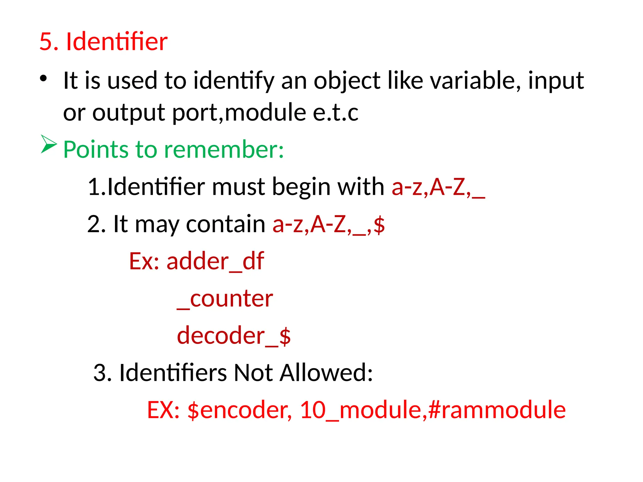
5. Identifier • Itis used to identify an object like variable, input or output port,module e.t.c Points to remember: 1.Identifier must begin with a-z,A-Z,_ 2. It may contain a-z,A-Z,_,$ Ex: adder_df _counter decoder_$ 3. Identifiers Not Allowed: EX: $encoder, 10_module,#rammodule
23.
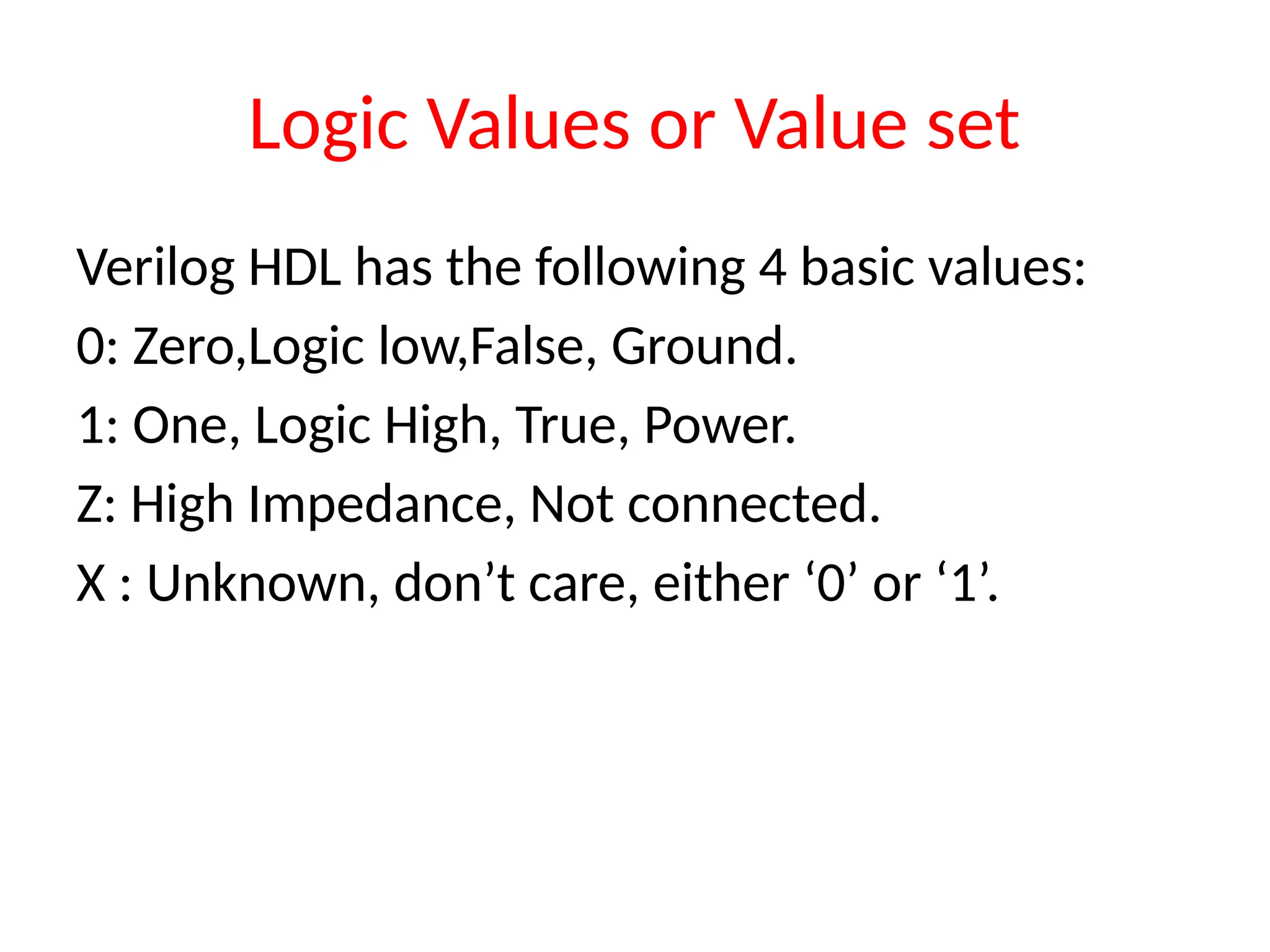
Logic Values orValue set Verilog HDL has the following 4 basic values: 0: Zero,Logic low,False, Ground. 1: One, Logic High, True, Power. Z: High Impedance, Not connected. X : Unknown, don’t care, either ‘0’ or ‘1’.
24.
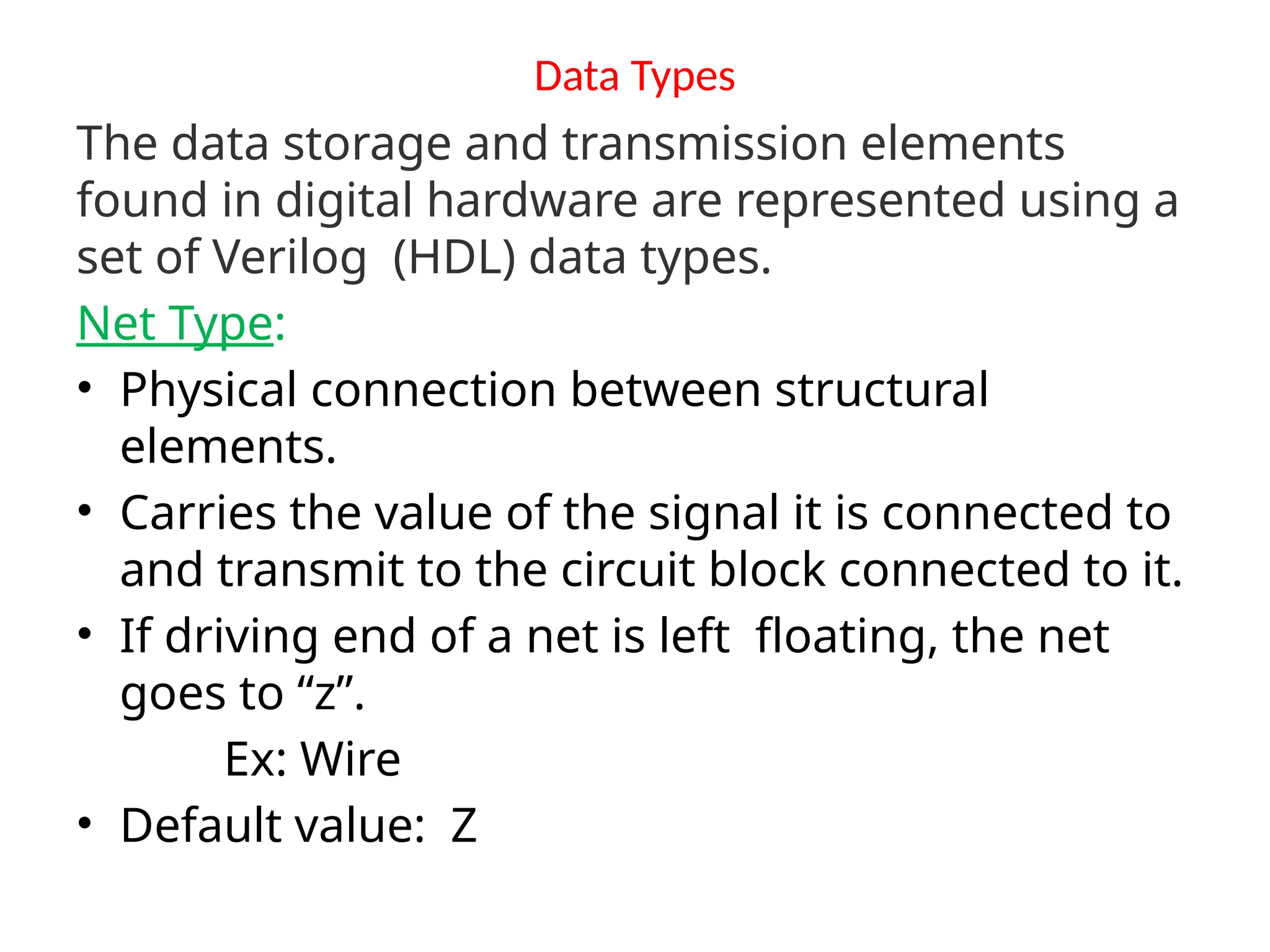
Data Types The datastorage and transmission elements found in digital hardware are represented using a set of Verilog (HDL) data types. Net Type: • Physical connection between structural elements. • Carries the value of the signal it is connected to and transmit to the circuit block connected to it. • If driving end of a net is left floating, the net goes to “z”. Ex: Wire • Default value: Z
25.
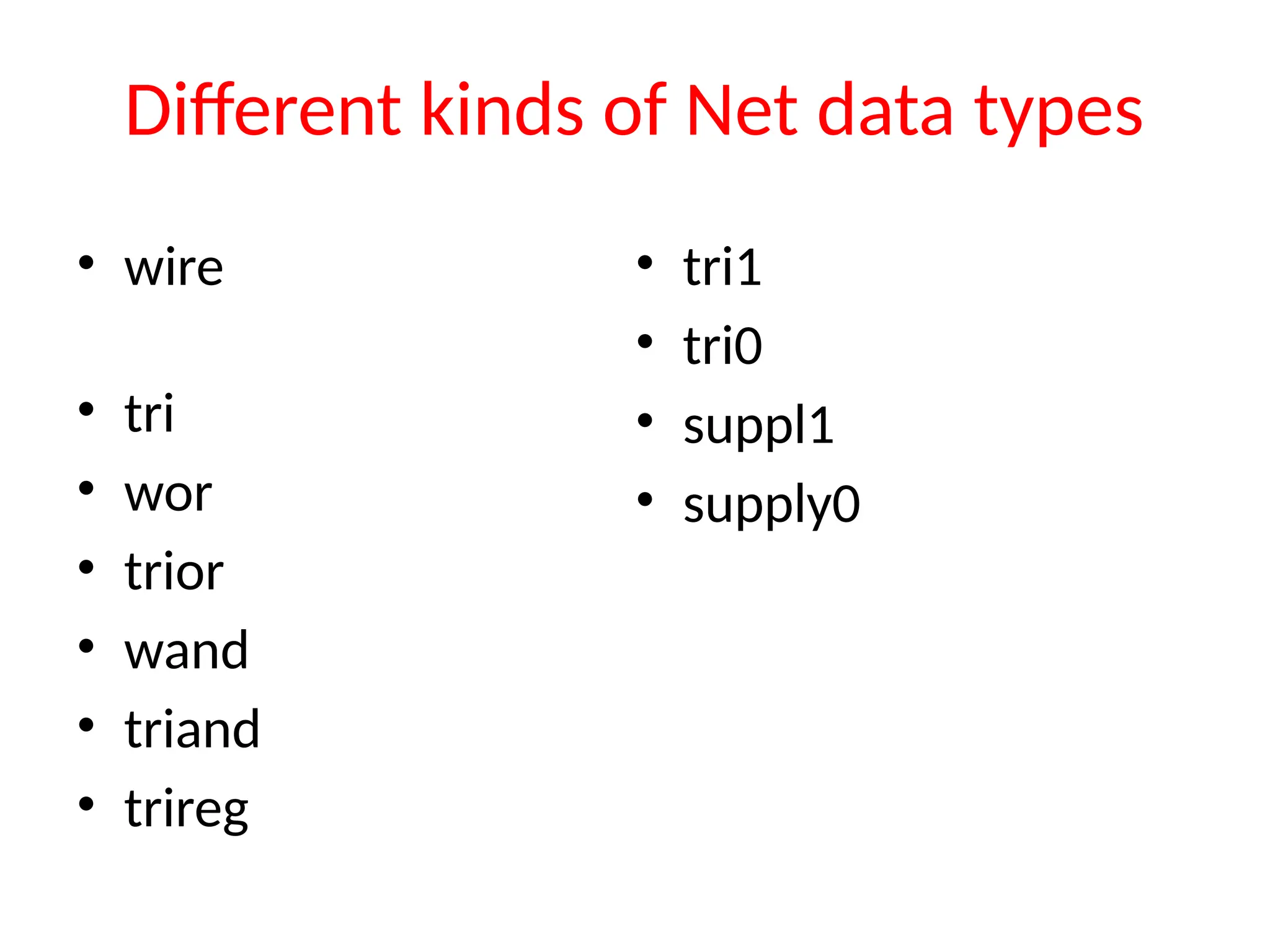
Different kinds ofNet data types • wire • tri • wor • trior • wand • triand • trireg • tri1 • tri0 • suppl1 • supply0
26.
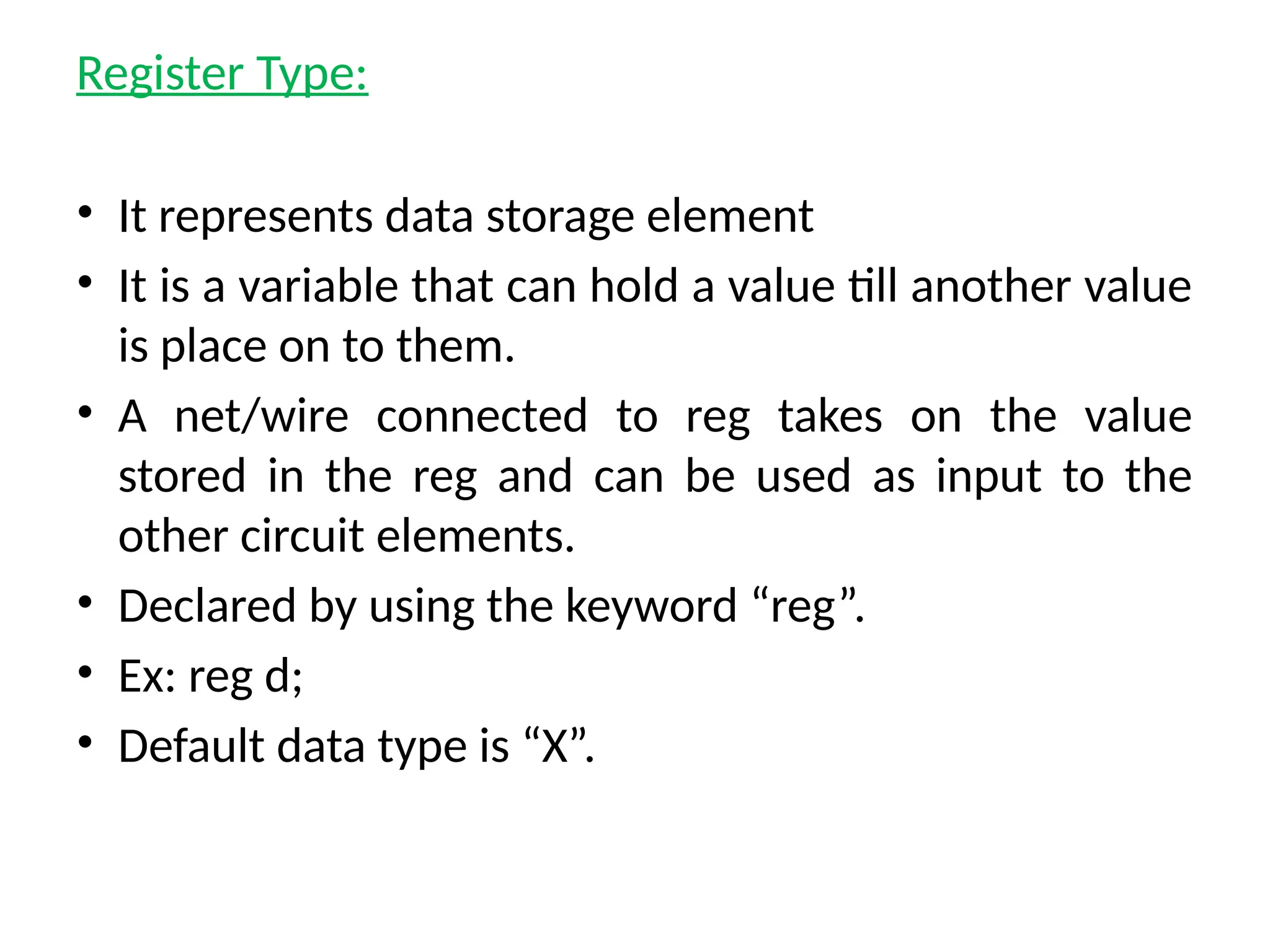
Register Type: • Itrepresents data storage element • It is a variable that can hold a value till another value is place on to them. • A net/wire connected to reg takes on the value stored in the reg and can be used as input to the other circuit elements. • Declared by using the keyword “reg”. • Ex: reg d; • Default data type is “X”.
27.
Scalars & Vectors •Entities representing single bits (Whether the bit is stored,changed or transferred) called “ Scalar”. Ex: wire w1; //It is a 1-bit wire. • Multiple lines carry signals in clusters called “Vector” Ex: wire [msb:lsb] wire1,wire2,….. reg [msb:lsb] reg1,reg2,…. wire [6:0] clear; //It is a 7-bit wire. Ex: reg [msb:lsb] memory1[upper : lower]; reg [3:0] mem[63:0]; // An array of 64 4-bit registers. reg mem[4:0]; // An array of 5 1-bit registers.
28.
• Nets orreg data types can be declared as vectors(multiple bit widths). • If bit width is not mentioned, default is 1-bit. • Vectors are declared using [msb:lsb] Ex: wire a; //scalar net variable,default wire[7:0] a; // vector variable 8-bit wire[31:0] A,B,C; //3- variables 32bit each reg clk; //scalar register reg[0:40] address; //vector register,default
29.
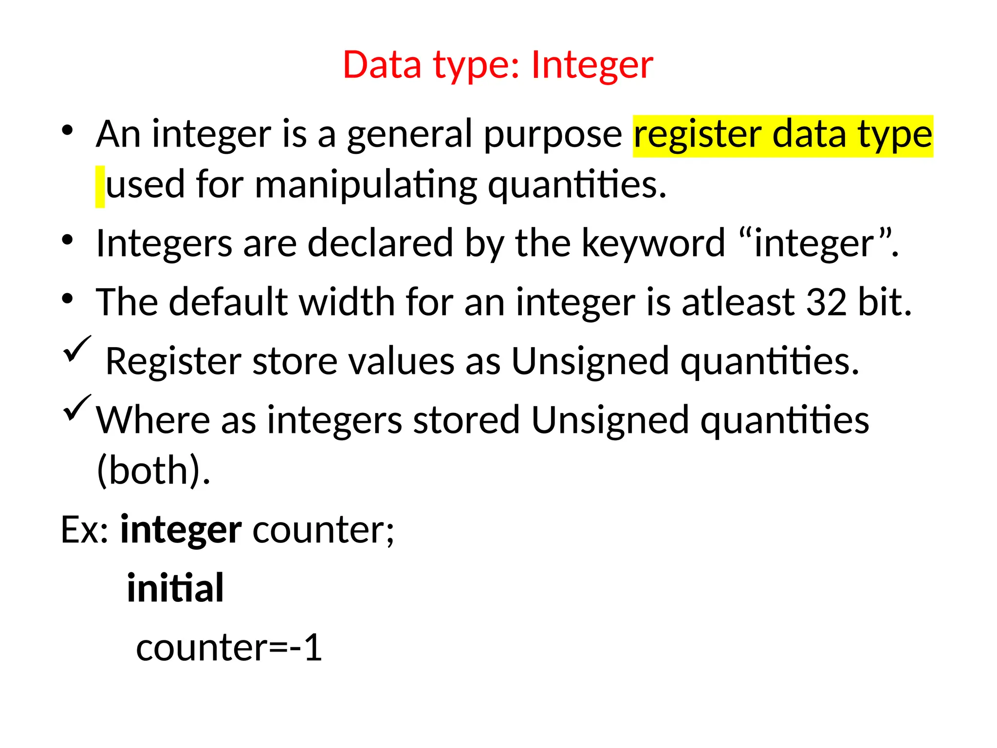
Data type: Integer •An integer is a general purpose register data type used for manipulating quantities. • Integers are declared by the keyword “integer”. • The default width for an integer is atleast 32 bit. Register store values as Unsigned quantities. Where as integers stored Unsigned quantities (both). Ex: integer counter; initial counter=-1
30.
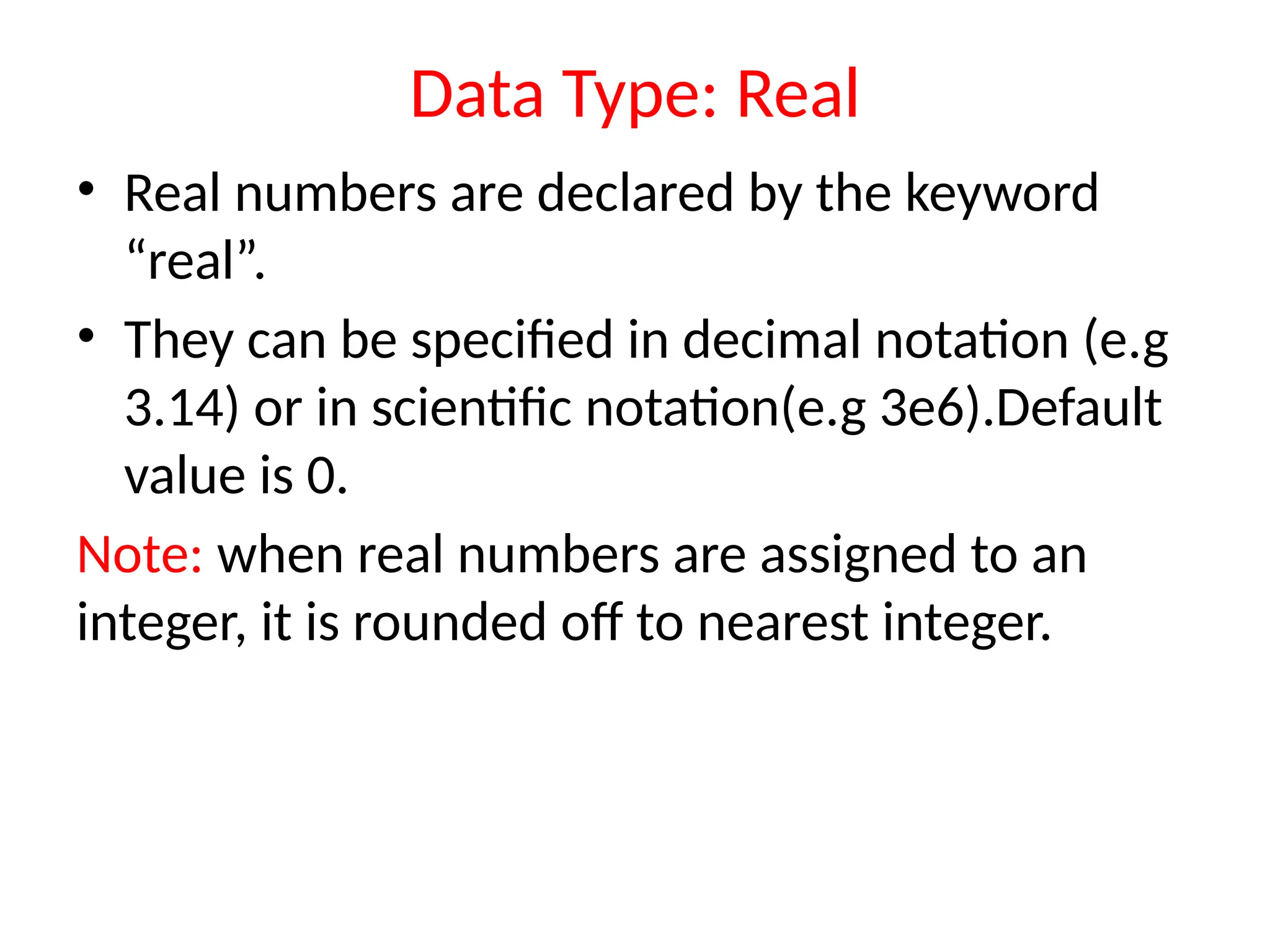
Data Type: Real •Real numbers are declared by the keyword “real”. • They can be specified in decimal notation (e.g 3.14) or in scientific notation(e.g 3e6).Default value is 0. Note: when real numbers are assigned to an integer, it is rounded off to nearest integer.
31.
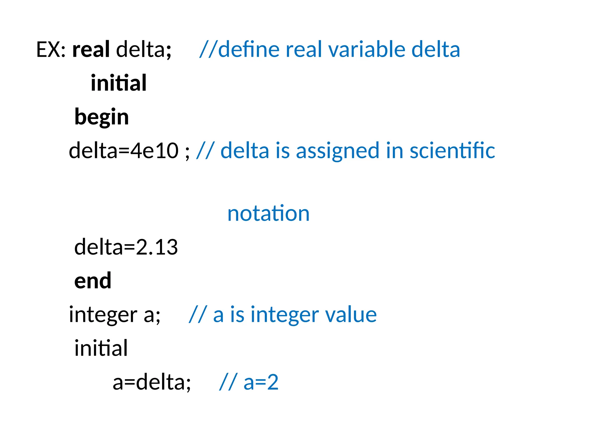
EX: real delta;//define real variable delta initial begin delta=4e10 ; // delta is assigned in scientific notation delta=2.13 end integer a; // a is integer value initial a=delta; // a=2
32.
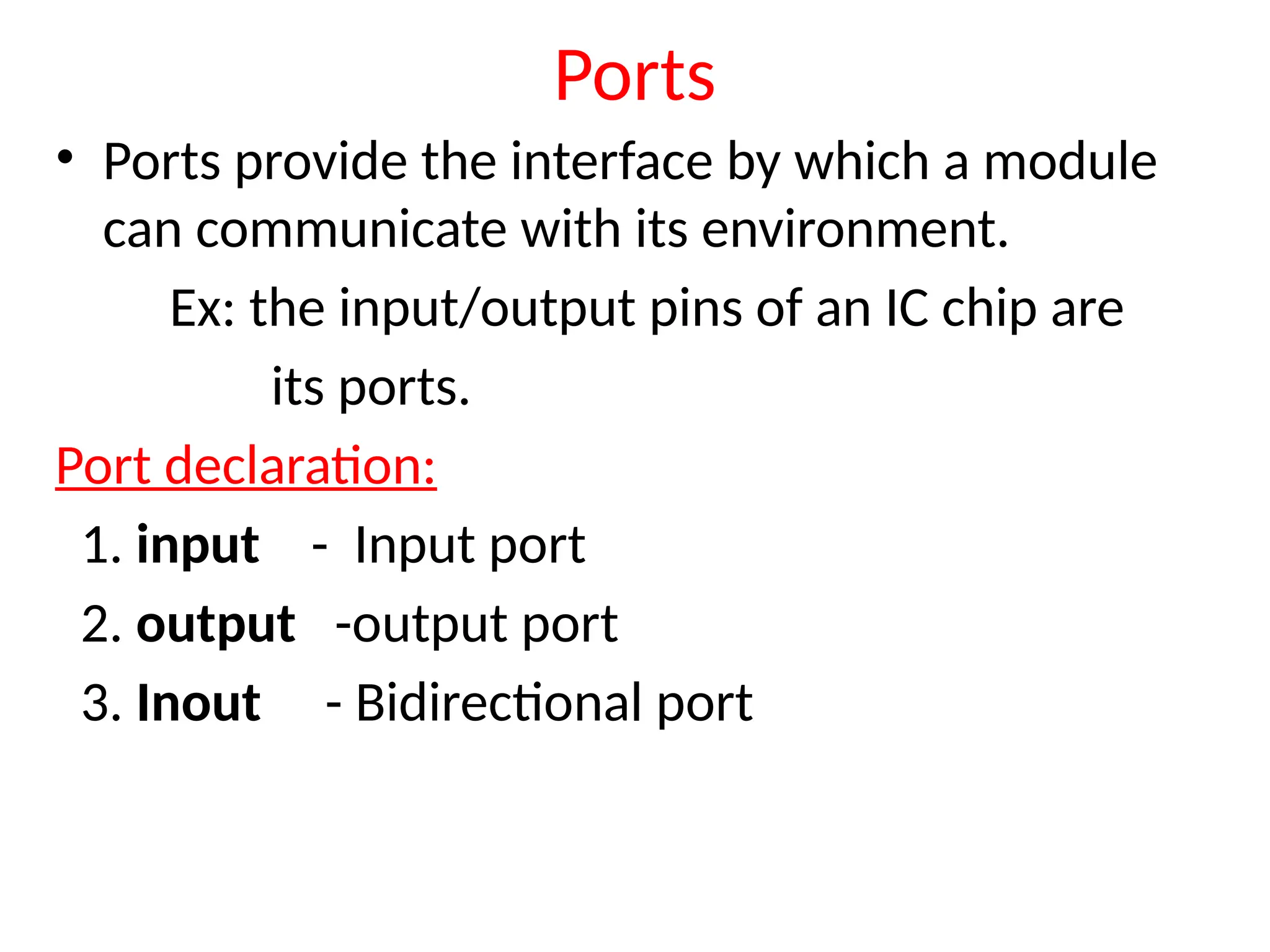
Ports • Ports providethe interface by which a module can communicate with its environment. Ex: the input/output pins of an IC chip are its ports. Port declaration: 1. input - Input port 2. output -output port 3. Inout - Bidirectional port
33.
• Input declaration: Scalar:input list of identifiers Ex: input A,B,C_in; Vector: input [range] list of input identifiers Ex: input[15:0] A,B, data; • Output declaration: Scalar: output list of identifiers Ex: output C_out, 0V, MINUS; Vector: output [range] list of input identifiers Ex: output[7:0] ACC,REG_IN;
34.
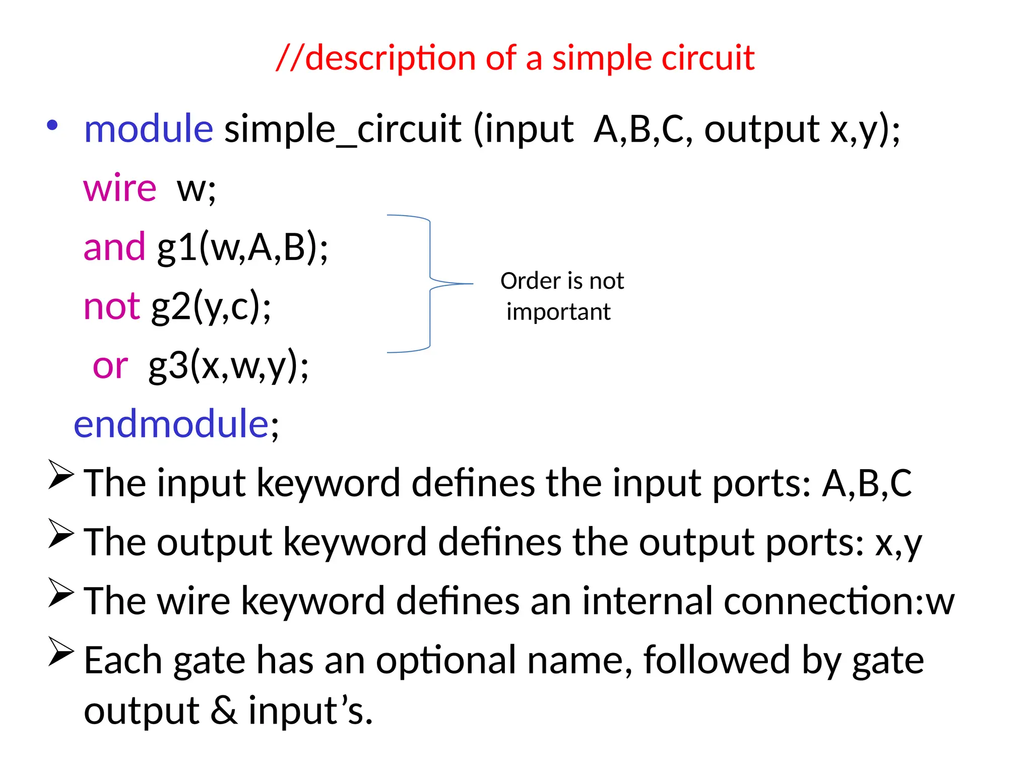
//description of asimple circuit • module simple_circuit (input A,B,C, output x,y); wire w; and g1(w,A,B); not g2(y,c); or g3(x,w,y); endmodule; The input keyword defines the input ports: A,B,C The output keyword defines the output ports: x,y The wire keyword defines an internal connection:w Each gate has an optional name, followed by gate output & input’s. Order is not important
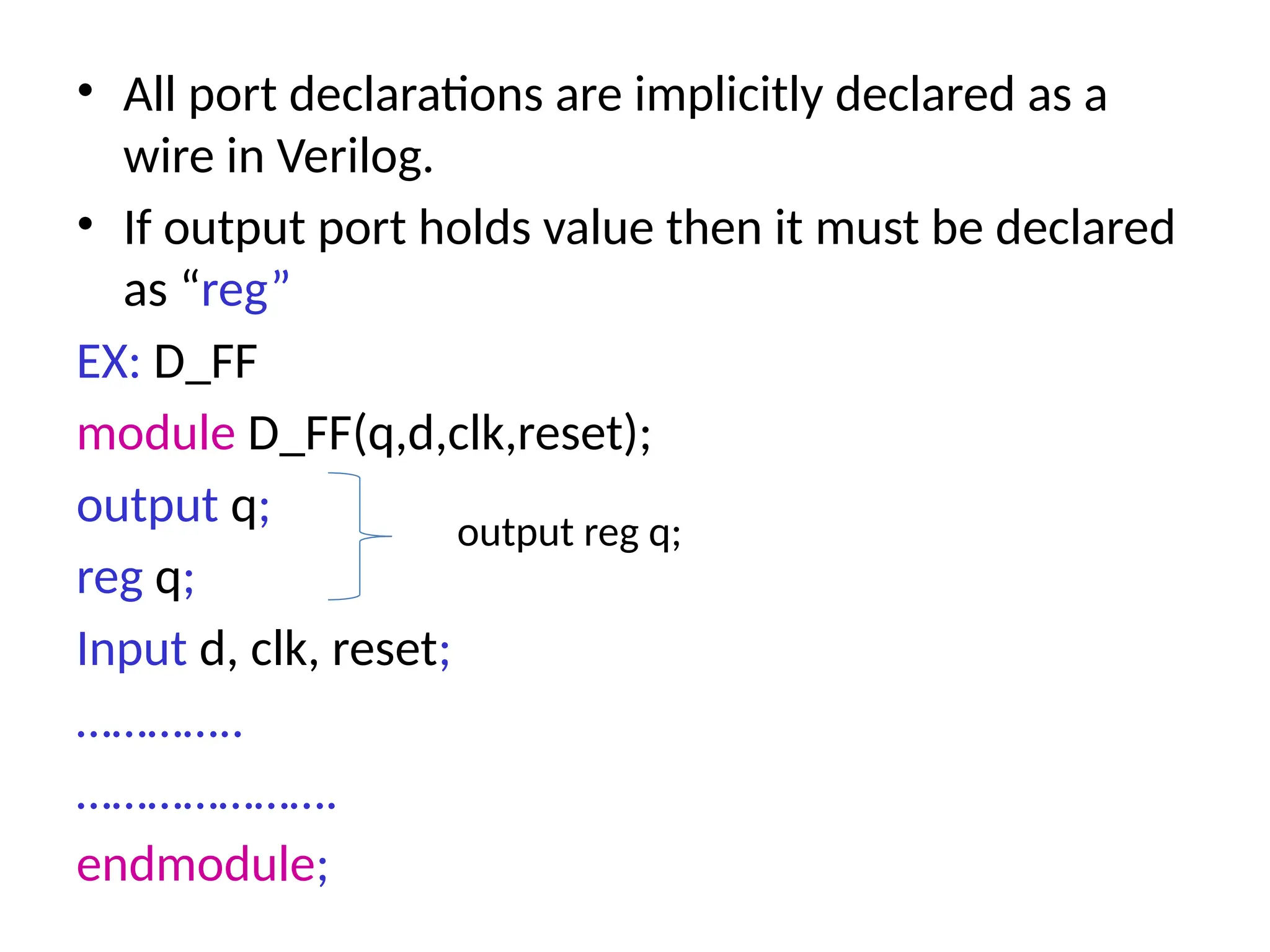
• All portdeclarations are implicitly declared as a wire in Verilog. • If output port holds value then it must be declared as “reg” EX: D_FF module D_FF(q,d,clk,reset); output q; reg q; Input d, clk, reset; ………….. …………………. endmodule; output reg q;
37.
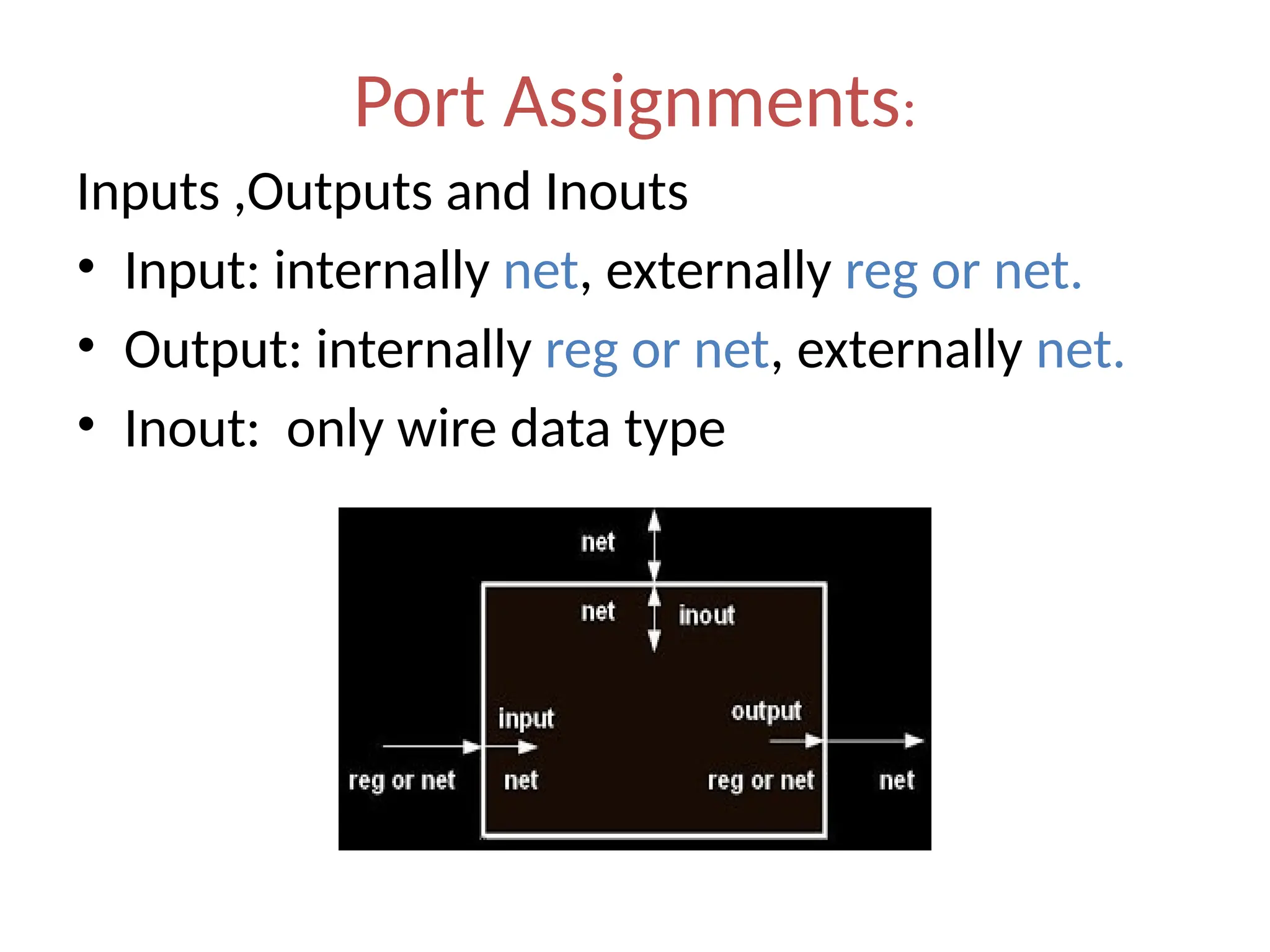
Port Assignments: Inputs ,Outputsand Inouts • Input: internally net, externally reg or net. • Output: internally reg or net, externally net. • Inout: only wire data type
38.
Verilog Expressions &operands • Expressions are constructs that combine operators and operands to produce a result. Example: a^b addr1[20:17]+addr2[20:17] in1|in2 • Operands can be constants,integers,real numbers,nets,registers,time,bit-select,part- select or function calls.
39.
Verilog operators Operators acton operands to produce desired result. Example: d1 && d2 // && is an operator on operands d1 and d2 !a[0] // ! is an operator on operands a[0] B>>1 // is an operator on operands B and 1
40.
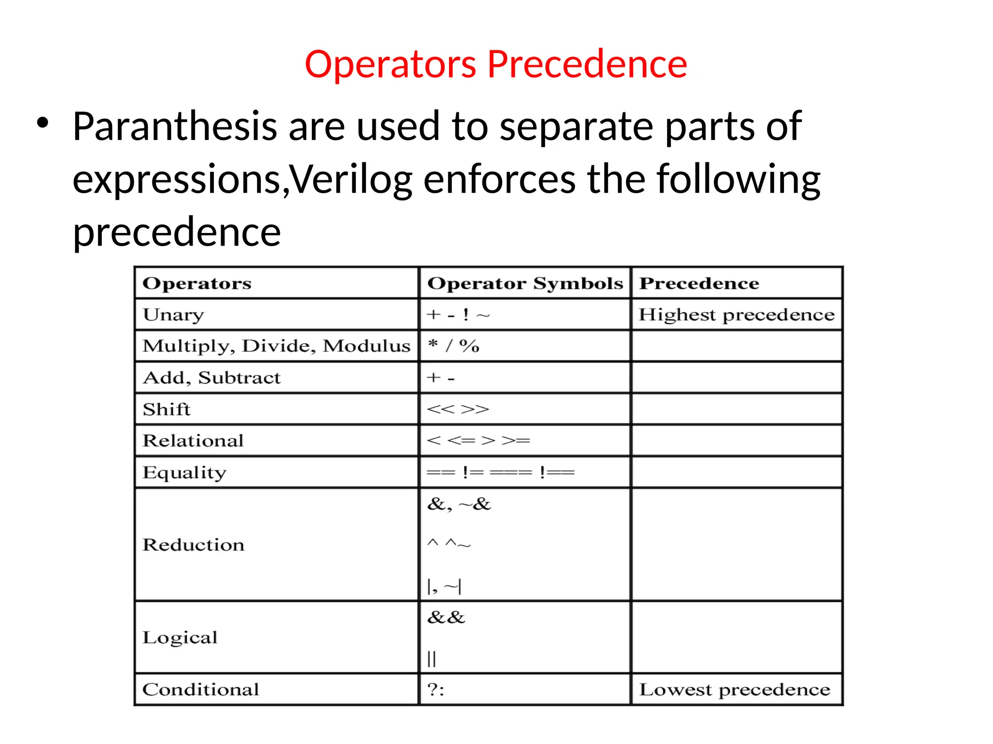
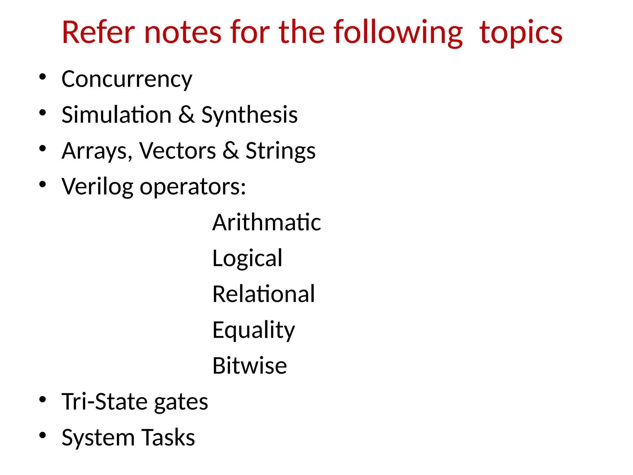
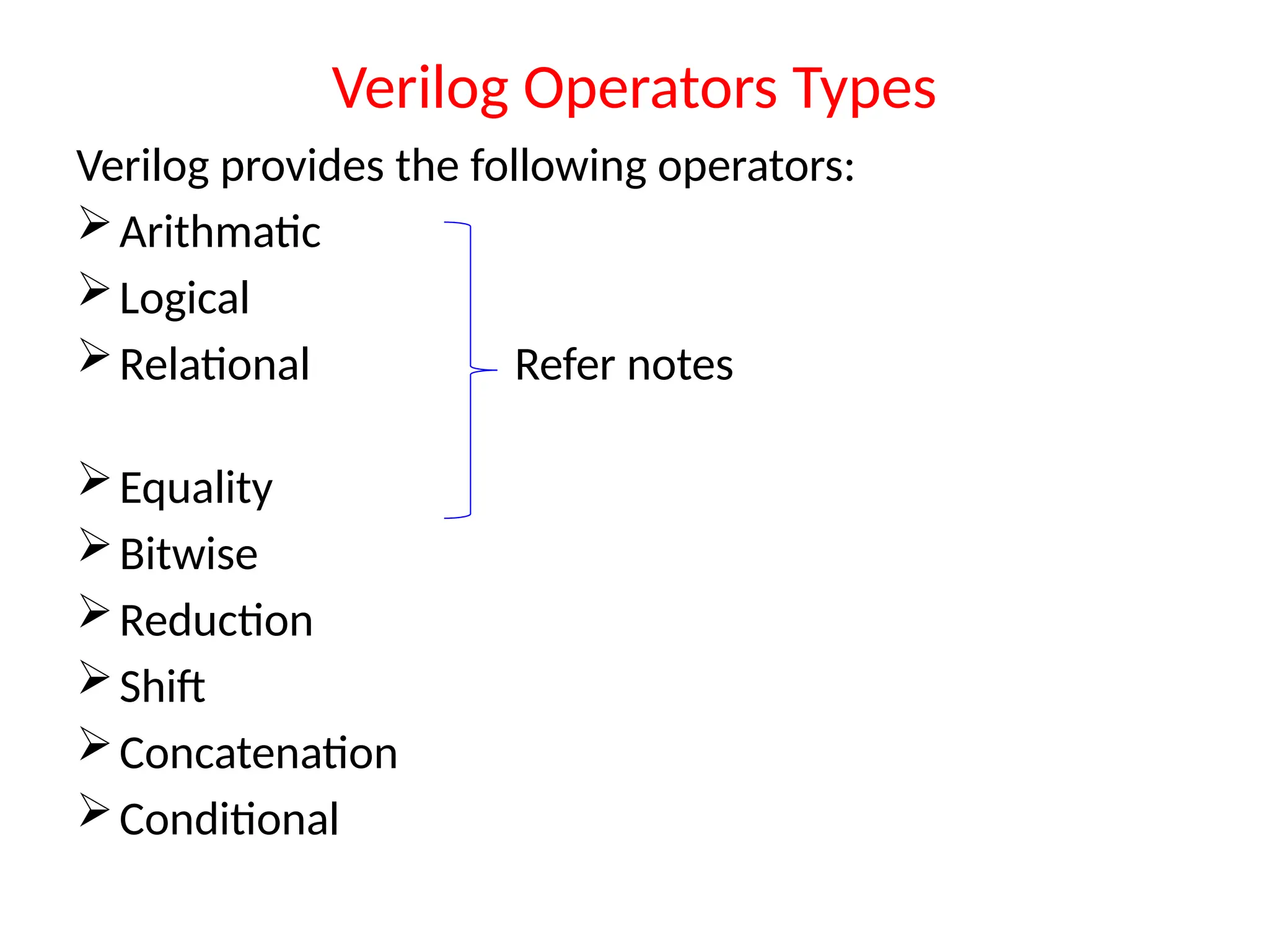
Verilog Operators Types Verilogprovides the following operators: Arithmatic Logical Relational Refer notes Equality Bitwise Reduction Shift Concatenation Conditional
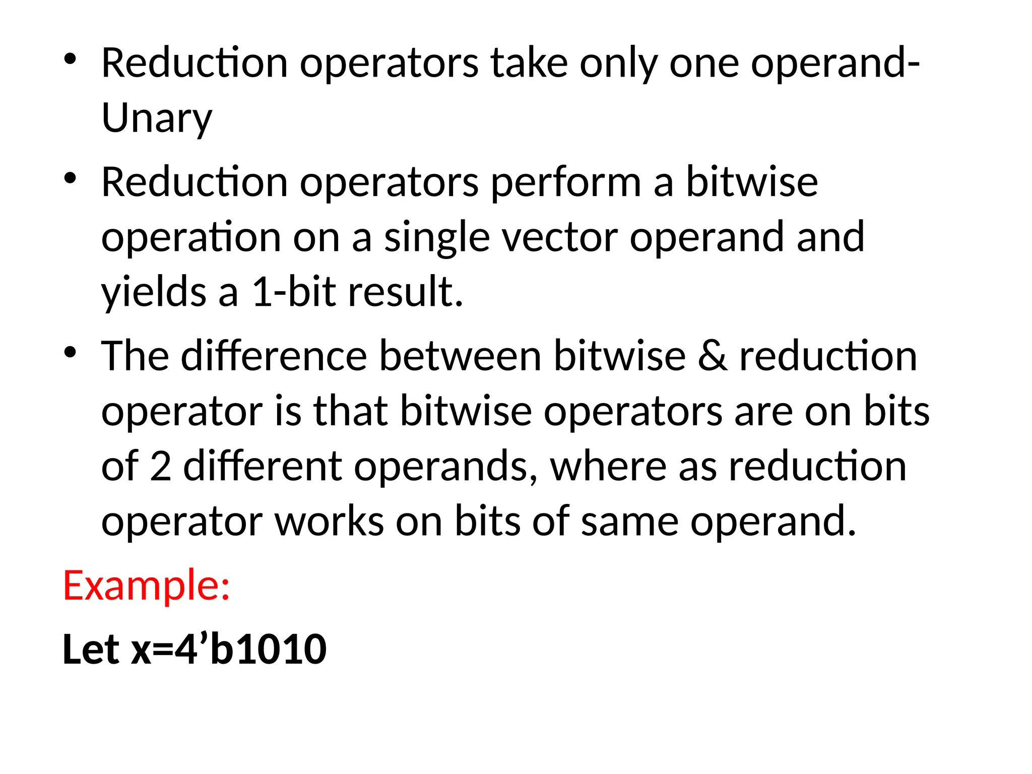
• Reduction operatorstake only one operand- Unary • Reduction operators perform a bitwise operation on a single vector operand and yields a 1-bit result. • The difference between bitwise & reduction operator is that bitwise operators are on bits of 2 different operands, where as reduction operator works on bits of same operand. Example: Let x=4’b1010
43.
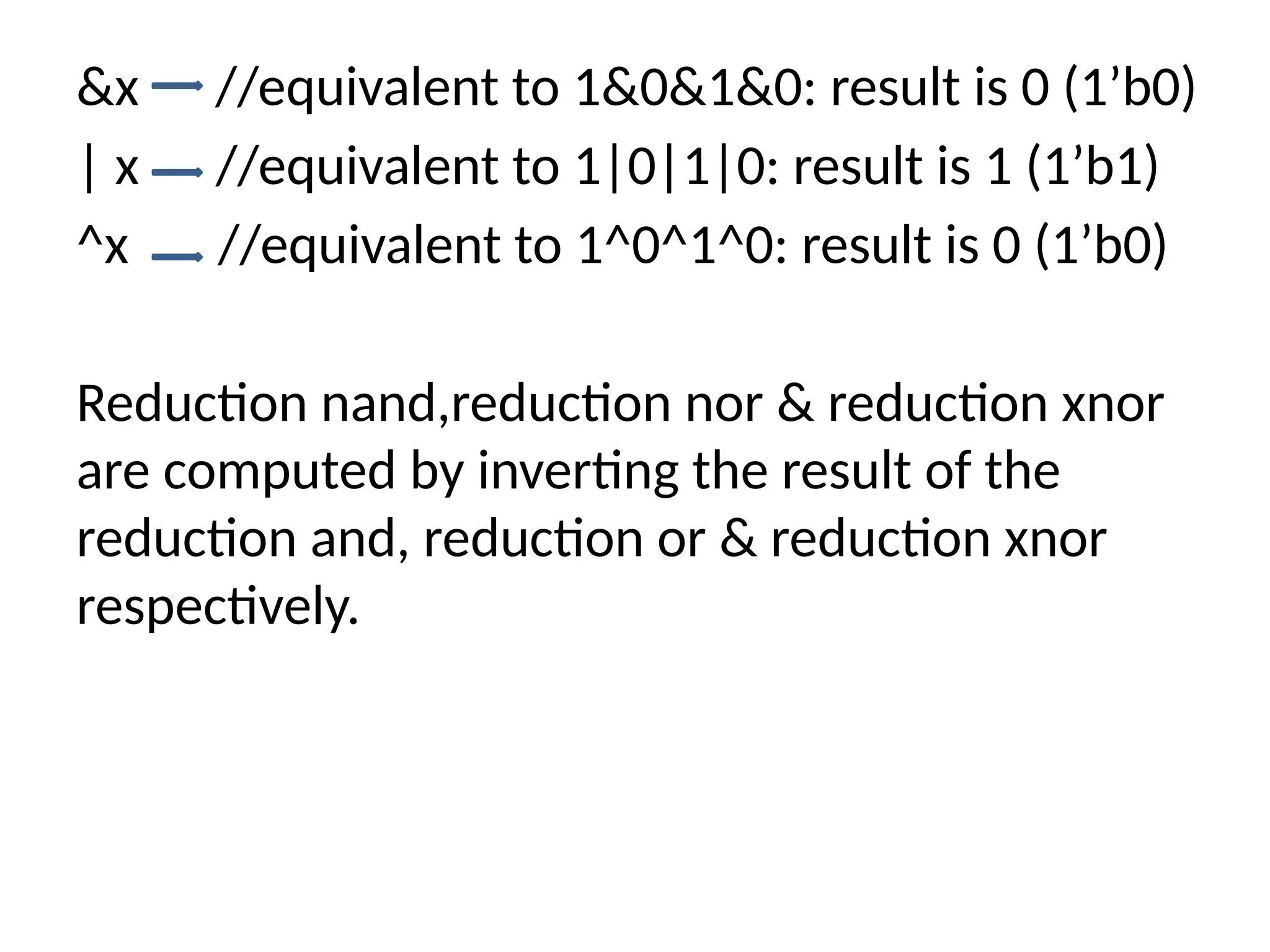
&x //equivalent to1&0&1&0: result is 0 (1’b0) | x //equivalent to 1|0|1|0: result is 1 (1’b1) ^x //equivalent to 1^0^1^0: result is 0 (1’b0) Reduction nand,reduction nor & reduction xnor are computed by inverting the result of the reduction and, reduction or & reduction xnor respectively.
44.
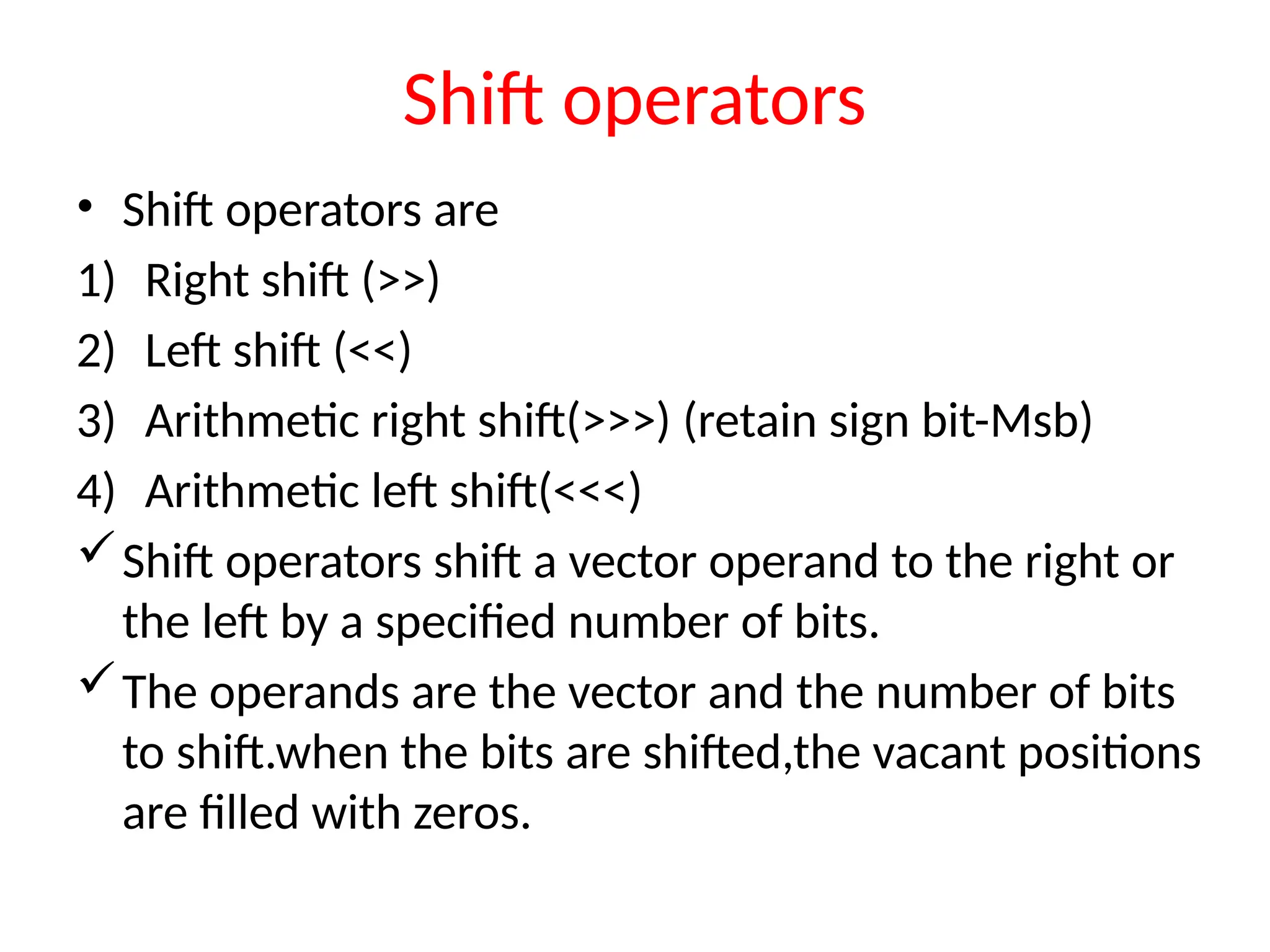
Shift operators • Shiftoperators are 1) Right shift (>>) 2) Left shift (<<) 3) Arithmetic right shift(>>>) (retain sign bit-Msb) 4) Arithmetic left shift(<<<) Shift operators shift a vector operand to the right or the left by a specified number of bits. The operands are the vector and the number of bits to shift.when the bits are shifted,the vacant positions are filled with zeros.
45.
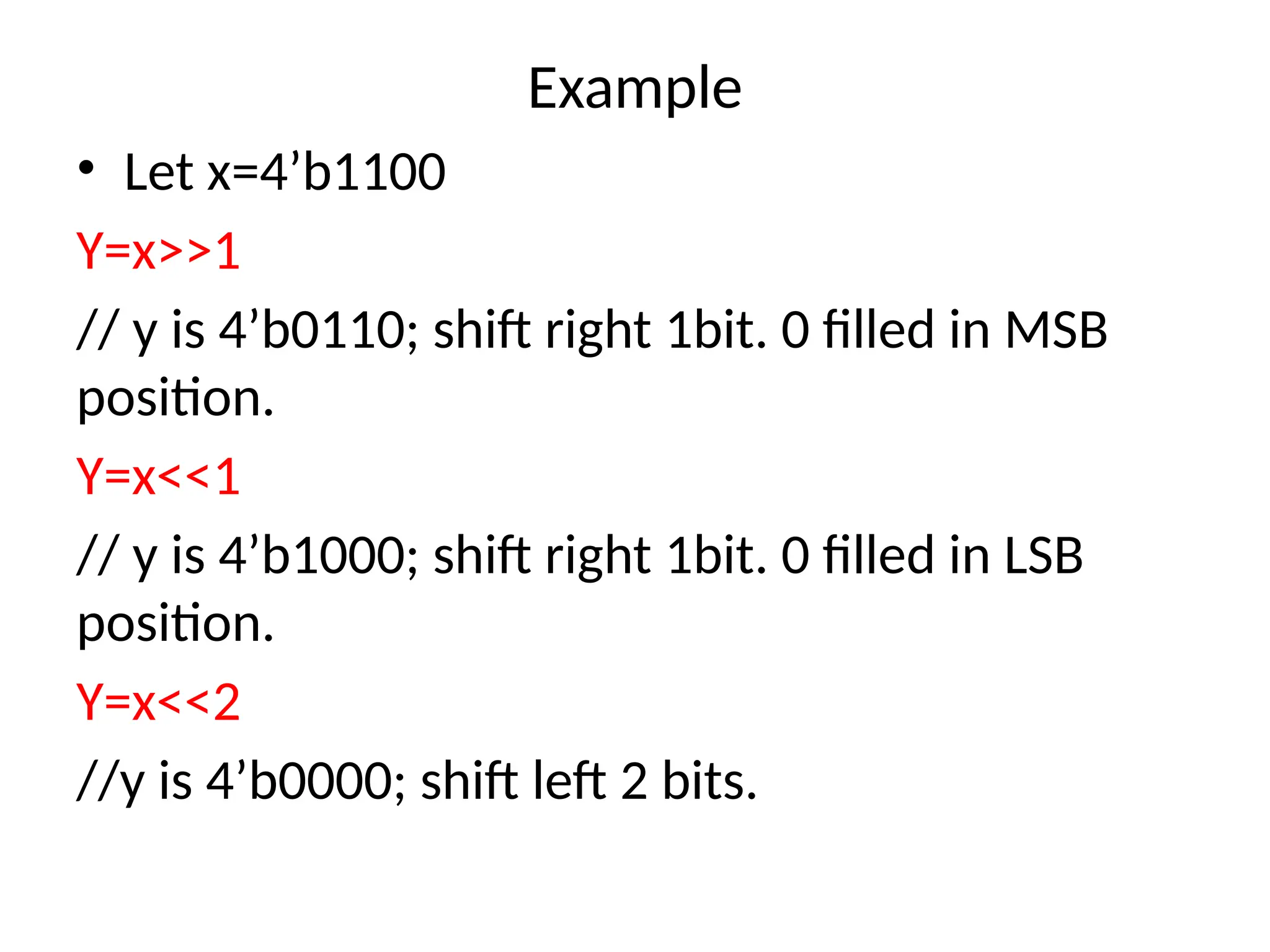
Example • Let x=4’b1100 Y=x>>1 //y is 4’b0110; shift right 1bit. 0 filled in MSB position. Y=x<<1 // y is 4’b1000; shift right 1bit. 0 filled in LSB position. Y=x<<2 //y is 4’b0000; shift left 2 bits.
46.
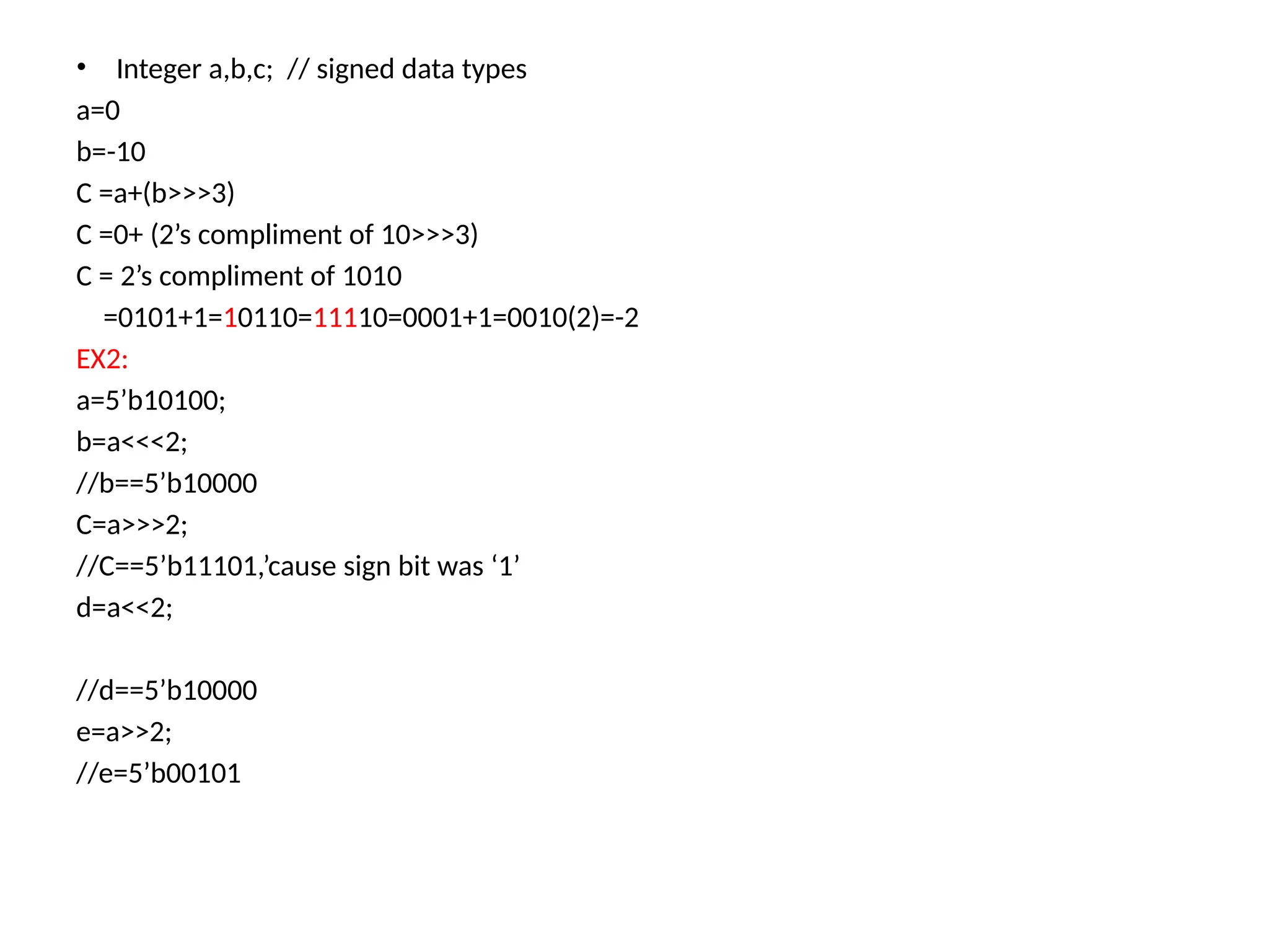
• Integer a,b,c;// signed data types a=0 b=-10 C =a+(b>>>3) C =0+ (2’s compliment of 10>>>3) C = 2’s compliment of 1010 =0101+1=10110=11110=0001+1=0010(2)=-2 EX2: a=5’b10100; b=a<<<2; //b==5’b10000 C=a>>>2; //C==5’b11101,’cause sign bit was ‘1’ d=a<<2; //d==5’b10000 e=a>>2; //e=5’b00101
47.
CONCATENATION OPERATORS • Concatenationoperator({ , })-append multiple operands • The operands must be sized,unsized operands are not allowed because the size of each operand must be known for the computation of the size of the result. Example : Let A=1’b1,B=2’b00,C=2’b10,D=3’b110 • Y={B,C} Result is 4’b0010 • Y={A,B,C,D,3’b001} Result is 11’b10010110001 • Y={A,B[0],C[1]} RESULT IS 3’b101
48.
Replication Operators • Repetitiveconcatenation of the same number can be expressed by using a replication constant • A replication constant specifies how many time to replicate the number inside the brackets({}) Example: reg A; reg [1:0] B,C; reg [2:0]D; A=1’b1;B=2’b00;C=2’b10;D=3’b110;
49.
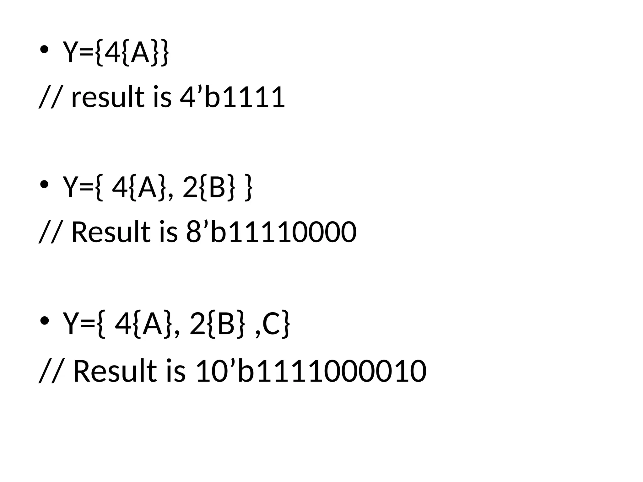
• Y={4{A}} // resultis 4’b1111 • Y={ 4{A}, 2{B} } // Result is 8’b11110000 • Y={ 4{A}, 2{B} ,C} // Result is 10’b1111000010
50.
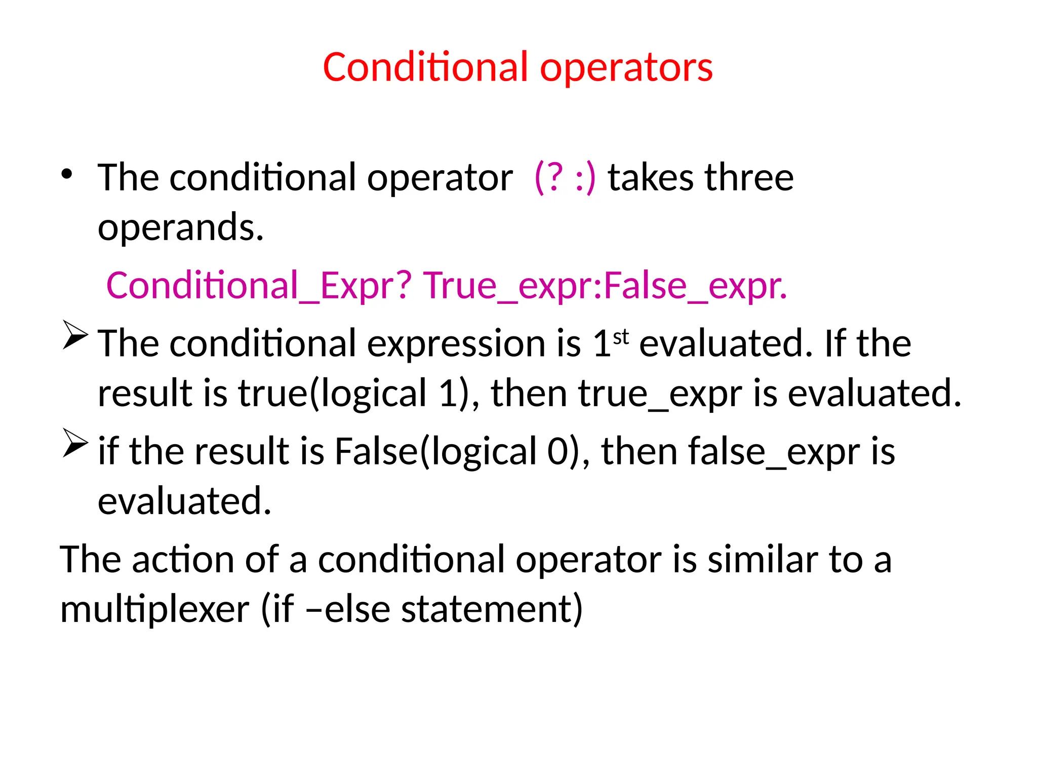
Conditional operators • Theconditional operator (? :) takes three operands. Conditional_Expr? True_expr:False_expr. The conditional expression is 1st evaluated. If the result is true(logical 1), then true_expr is evaluated. if the result is False(logical 0), then false_expr is evaluated. The action of a conditional operator is similar to a multiplexer (if –else statement)
51.
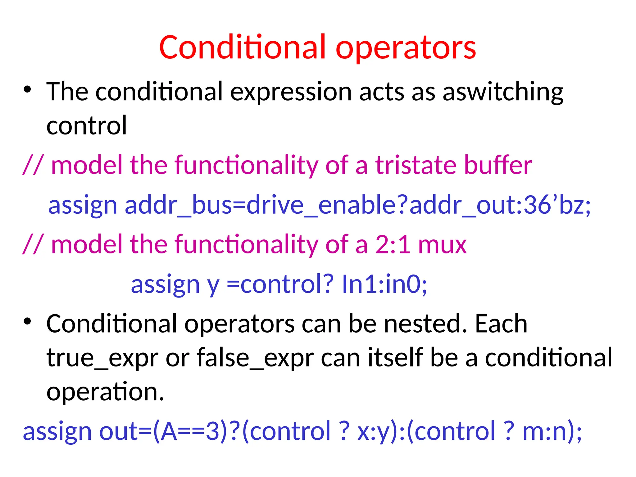
Conditional operators • Theconditional expression acts as aswitching control // model the functionality of a tristate buffer assign addr_bus=drive_enable?addr_out:36’bz; // model the functionality of a 2:1 mux assign y =control? In1:in0; • Conditional operators can be nested. Each true_expr or false_expr can itself be a conditional operation. assign out=(A==3)?(control ? x:y):(control ? m:n);

![Scalars & Vectors • Entities representing single bits (Whether the bit is stored,changed or transferred) called “ Scalar”. Ex: wire w1; //It is a 1-bit wire. • Multiple lines carry signals in clusters called “Vector” Ex: wire [msb:lsb] wire1,wire2,….. reg [msb:lsb] reg1,reg2,…. wire [6:0] clear; //It is a 7-bit wire. Ex: reg [msb:lsb] memory1[upper : lower]; reg [3:0] mem[63:0]; // An array of 64 4-bit registers. reg mem[4:0]; // An array of 5 1-bit registers.](https://image.slidesharecdn.com/dsdusingverilogunit-1ppt-251001033350-a4e0cc0c/75/DSD-using-VERILOG-FOR-ENGINEERING-STUDENTS-27-2048.jpg)
![• Nets or reg data types can be declared as vectors(multiple bit widths). • If bit width is not mentioned, default is 1-bit. • Vectors are declared using [msb:lsb] Ex: wire a; //scalar net variable,default wire[7:0] a; // vector variable 8-bit wire[31:0] A,B,C; //3- variables 32bit each reg clk; //scalar register reg[0:40] address; //vector register,default](https://image.slidesharecdn.com/dsdusingverilogunit-1ppt-251001033350-a4e0cc0c/75/DSD-using-VERILOG-FOR-ENGINEERING-STUDENTS-28-2048.jpg)
![• Input declaration: Scalar: input list of identifiers Ex: input A,B,C_in; Vector: input [range] list of input identifiers Ex: input[15:0] A,B, data; • Output declaration: Scalar: output list of identifiers Ex: output C_out, 0V, MINUS; Vector: output [range] list of input identifiers Ex: output[7:0] ACC,REG_IN;](https://image.slidesharecdn.com/dsdusingverilogunit-1ppt-251001033350-a4e0cc0c/75/DSD-using-VERILOG-FOR-ENGINEERING-STUDENTS-33-2048.jpg)
![Example : port declaration • module full_add4(sum,cout,a,b,cin); input [3:0]a,b; input cin; output [3:0]sum; output cout; …………….. ………………… endmodule; Unconnected ports: Verilog allows ports to remain unconnected. EX: full_add4 fa0(sum, , a,b,cin);](https://image.slidesharecdn.com/dsdusingverilogunit-1ppt-251001033350-a4e0cc0c/75/DSD-using-VERILOG-FOR-ENGINEERING-STUDENTS-35-2048.jpg)
![Verilog Expressions & operands • Expressions are constructs that combine operators and operands to produce a result. Example: a^b addr1[20:17]+addr2[20:17] in1|in2 • Operands can be constants,integers,real numbers,nets,registers,time,bit-select,part- select or function calls.](https://image.slidesharecdn.com/dsdusingverilogunit-1ppt-251001033350-a4e0cc0c/75/DSD-using-VERILOG-FOR-ENGINEERING-STUDENTS-38-2048.jpg)
![Verilog operators Operators act on operands to produce desired result. Example: d1 && d2 // && is an operator on operands d1 and d2 !a[0] // ! is an operator on operands a[0] B>>1 // is an operator on operands B and 1](https://image.slidesharecdn.com/dsdusingverilogunit-1ppt-251001033350-a4e0cc0c/75/DSD-using-VERILOG-FOR-ENGINEERING-STUDENTS-39-2048.jpg)
![CONCATENATION OPERATORS • Concatenation operator({ , })-append multiple operands • The operands must be sized,unsized operands are not allowed because the size of each operand must be known for the computation of the size of the result. Example : Let A=1’b1,B=2’b00,C=2’b10,D=3’b110 • Y={B,C} Result is 4’b0010 • Y={A,B,C,D,3’b001} Result is 11’b10010110001 • Y={A,B[0],C[1]} RESULT IS 3’b101](https://image.slidesharecdn.com/dsdusingverilogunit-1ppt-251001033350-a4e0cc0c/75/DSD-using-VERILOG-FOR-ENGINEERING-STUDENTS-47-2048.jpg)
![Replication Operators • Repetitive concatenation of the same number can be expressed by using a replication constant • A replication constant specifies how many time to replicate the number inside the brackets({}) Example: reg A; reg [1:0] B,C; reg [2:0]D; A=1’b1;B=2’b00;C=2’b10;D=3’b110;](https://image.slidesharecdn.com/dsdusingverilogunit-1ppt-251001033350-a4e0cc0c/75/DSD-using-VERILOG-FOR-ENGINEERING-STUDENTS-48-2048.jpg)