Download as PDF, PPTX


This document provides a comprehensive overview of industrial robotics, covering various components including drive systems, control systems, end effectors, and sensors, as well as applications in automation. It categorizes automation into fixed, programmable, and flexible types, detailing robots' configurations such as Cartesian, cylindrical, and articulated designs, and their respective functionalities. The text also highlights the types of actuators that drive robots, such as electric, hydraulic, and pneumatic systems.
Introduction to the robotics field and its topics like automation and types of industrial automation.
Detailed descriptions of Fixed, Programmable, and Flexible automation in industrial contexts.
Official definition of industrial robots by RIA and their classification in automation types.
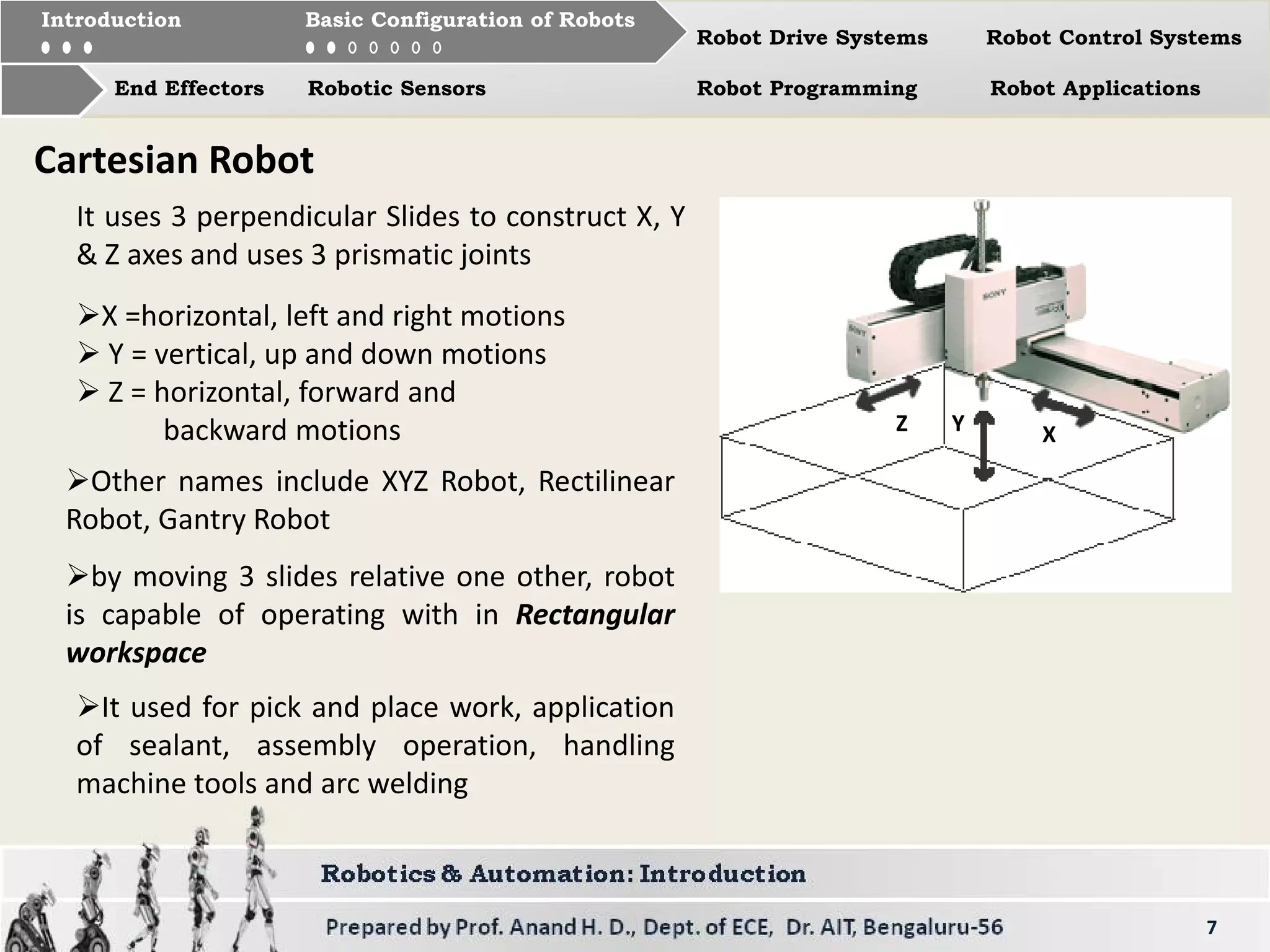
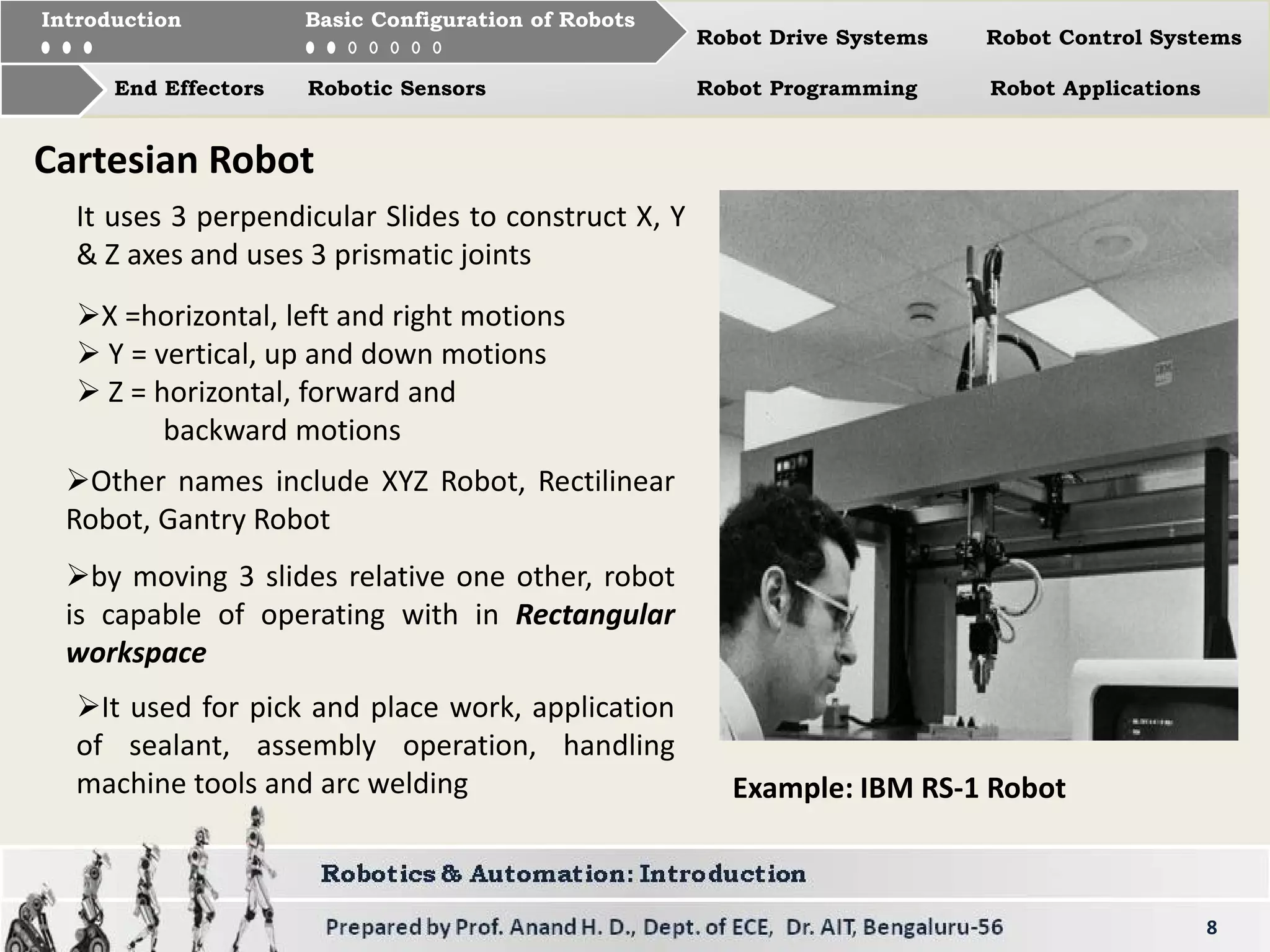
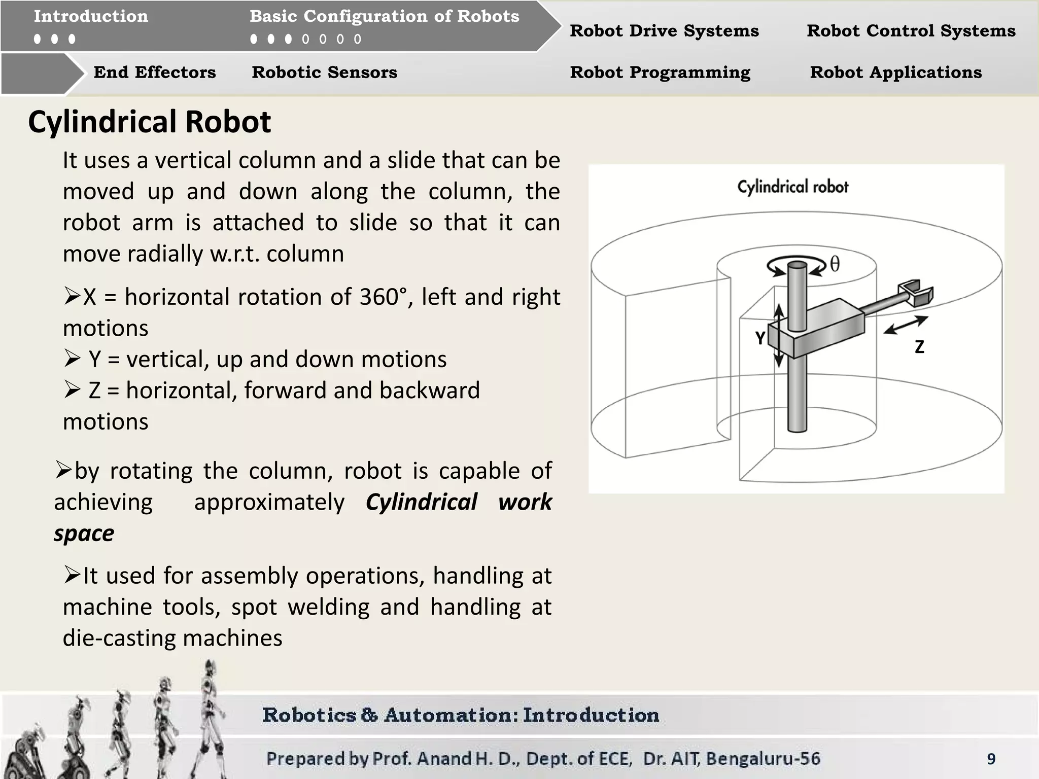
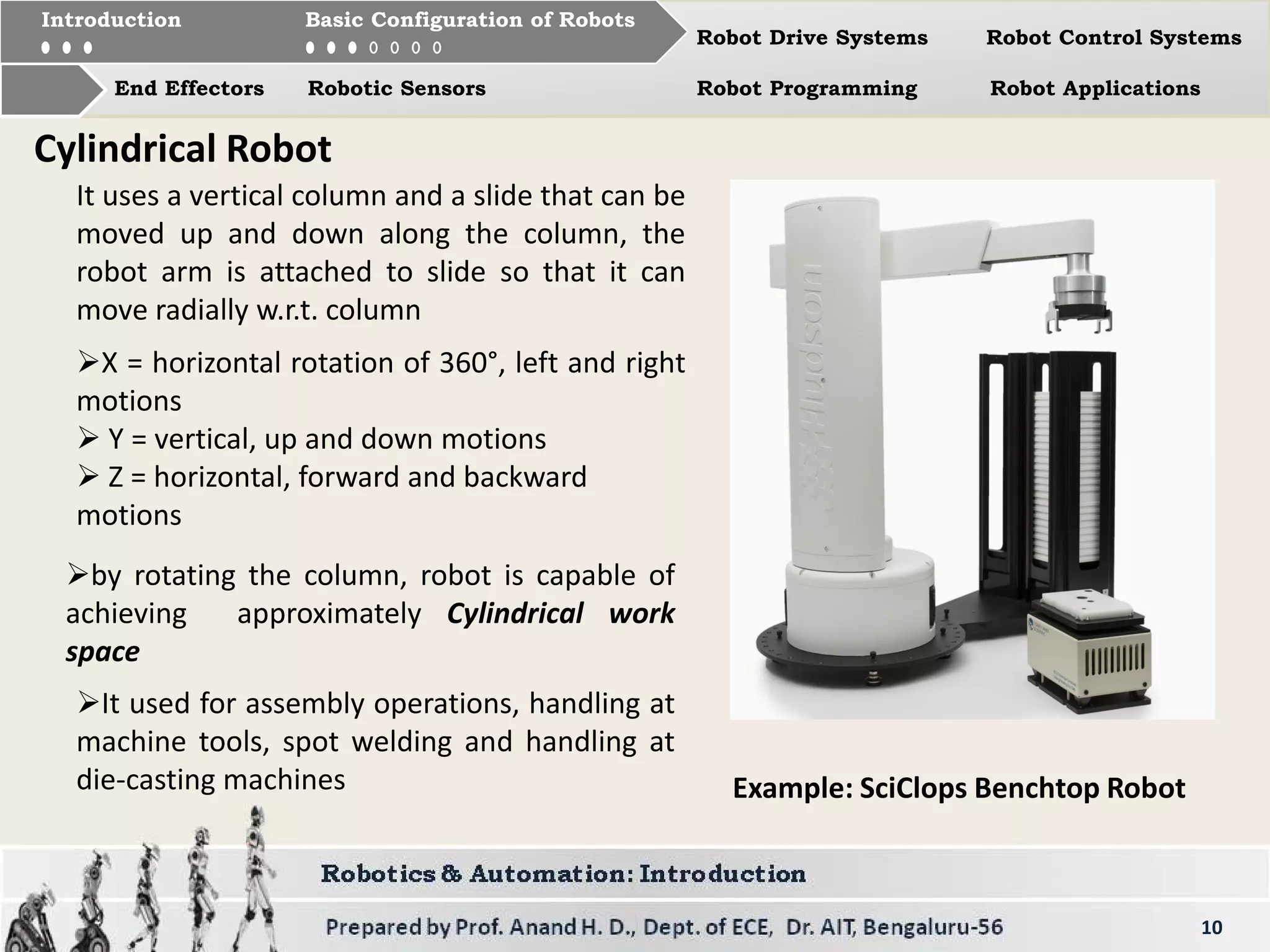
Description of Cartesian and Cylindrical robots, their movements, applications, and examples.
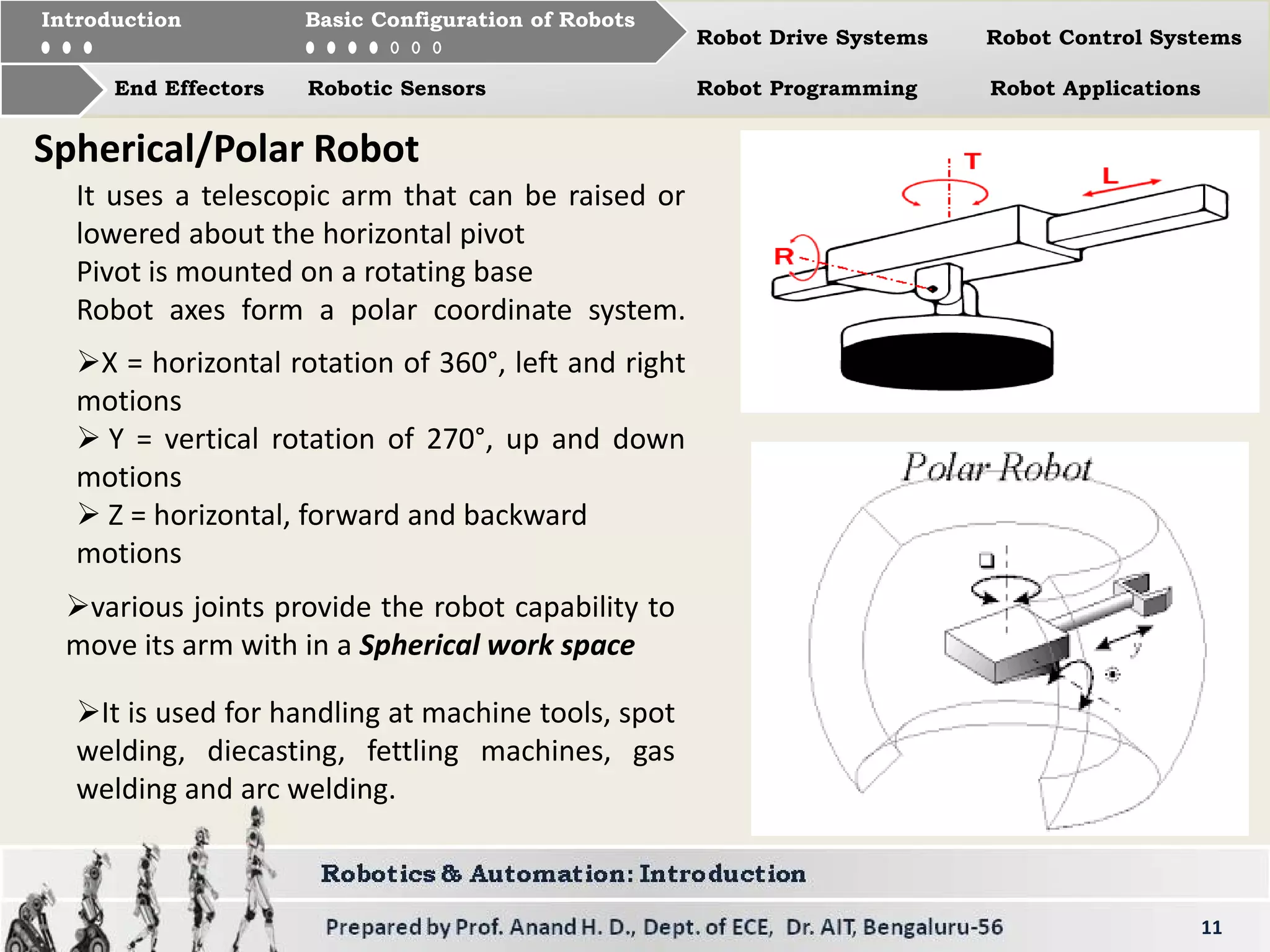
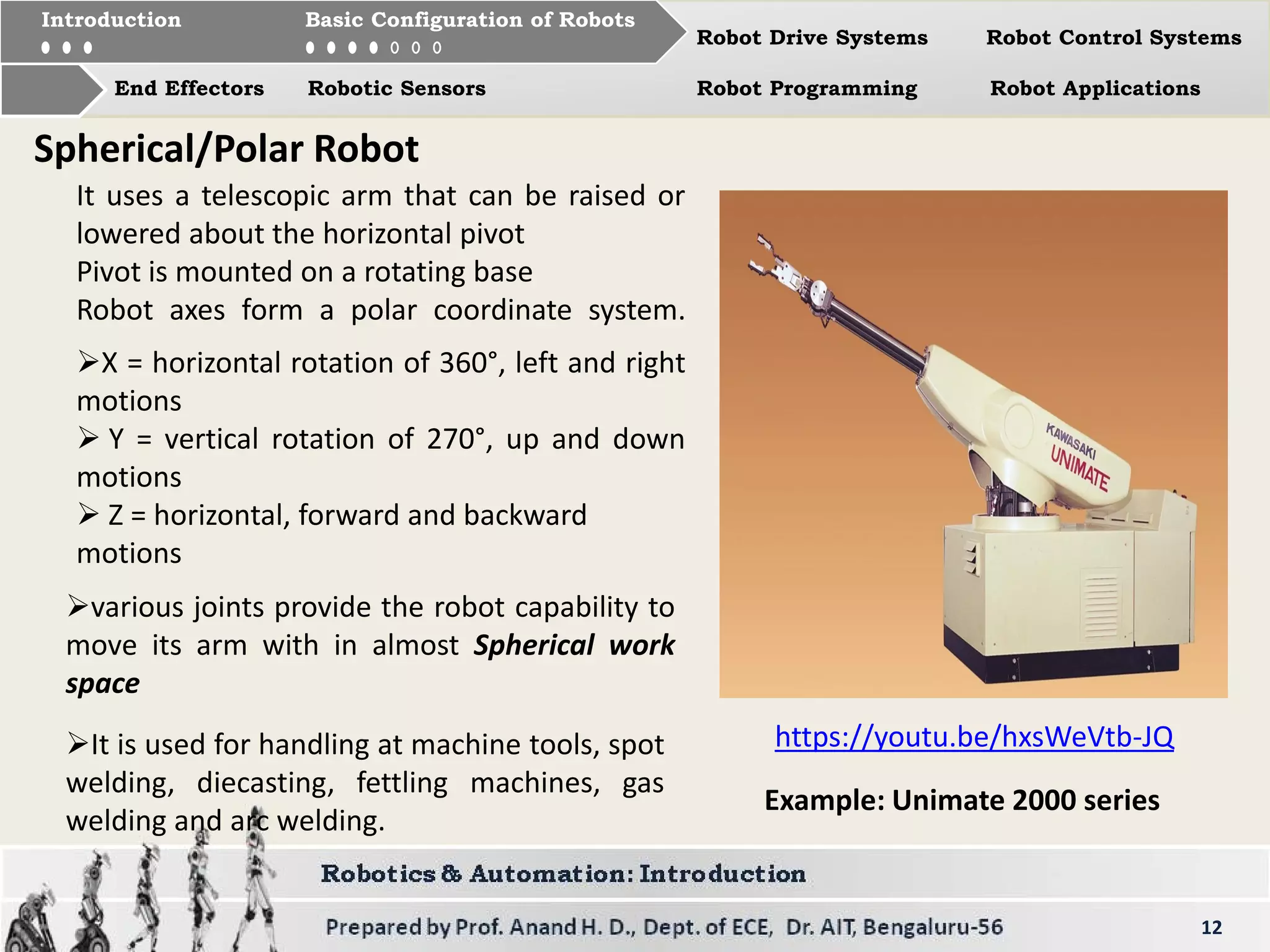
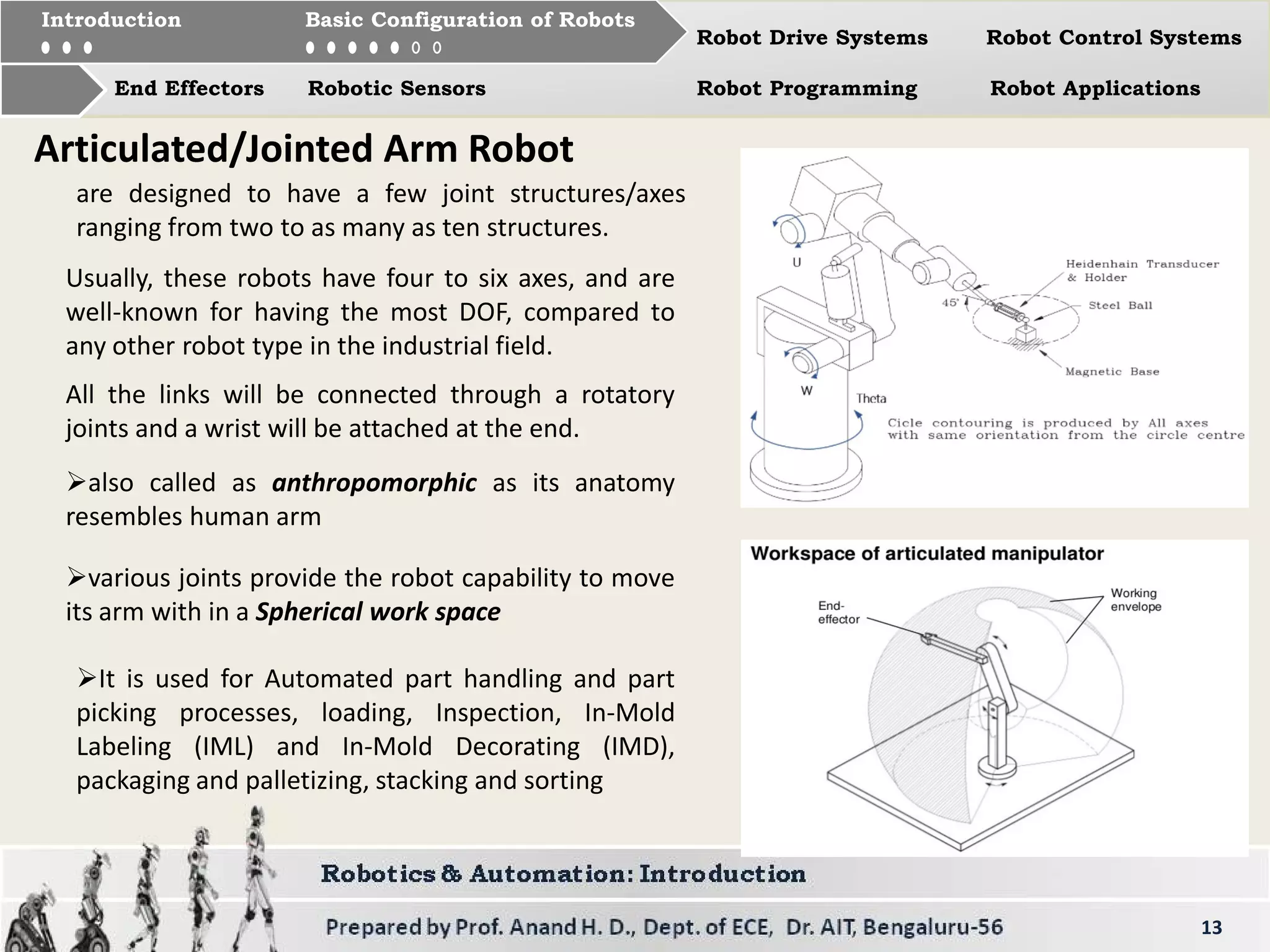
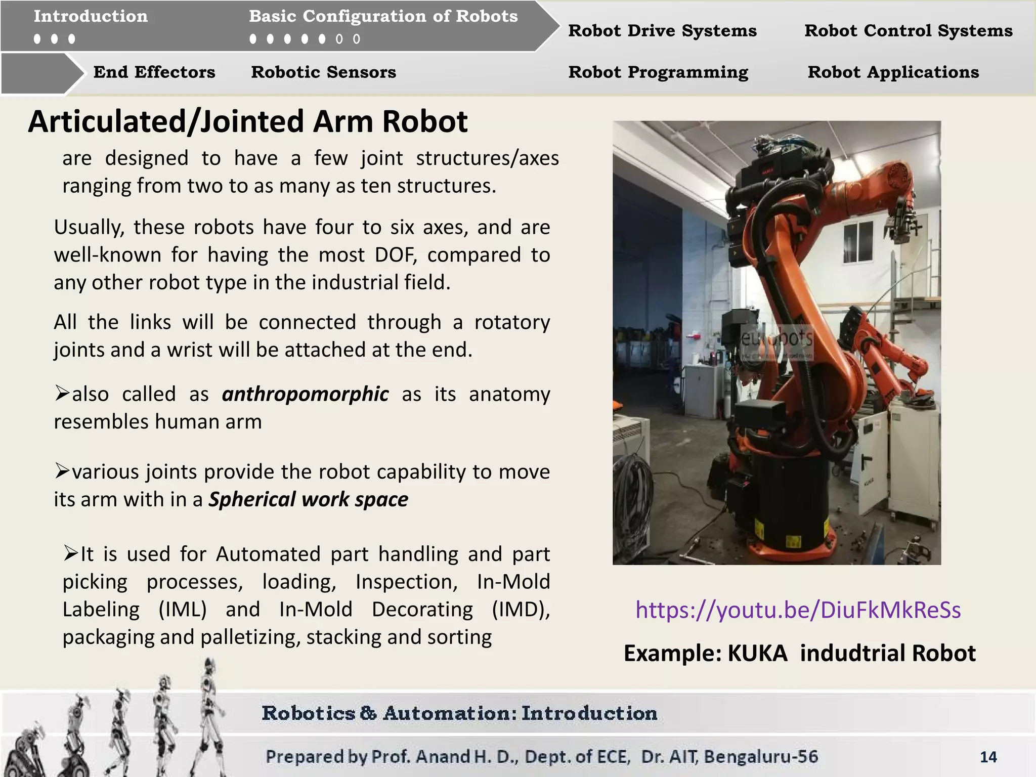
Overview of Spherical, Articulated and Jointed Arm robots, including their uses and characteristics.
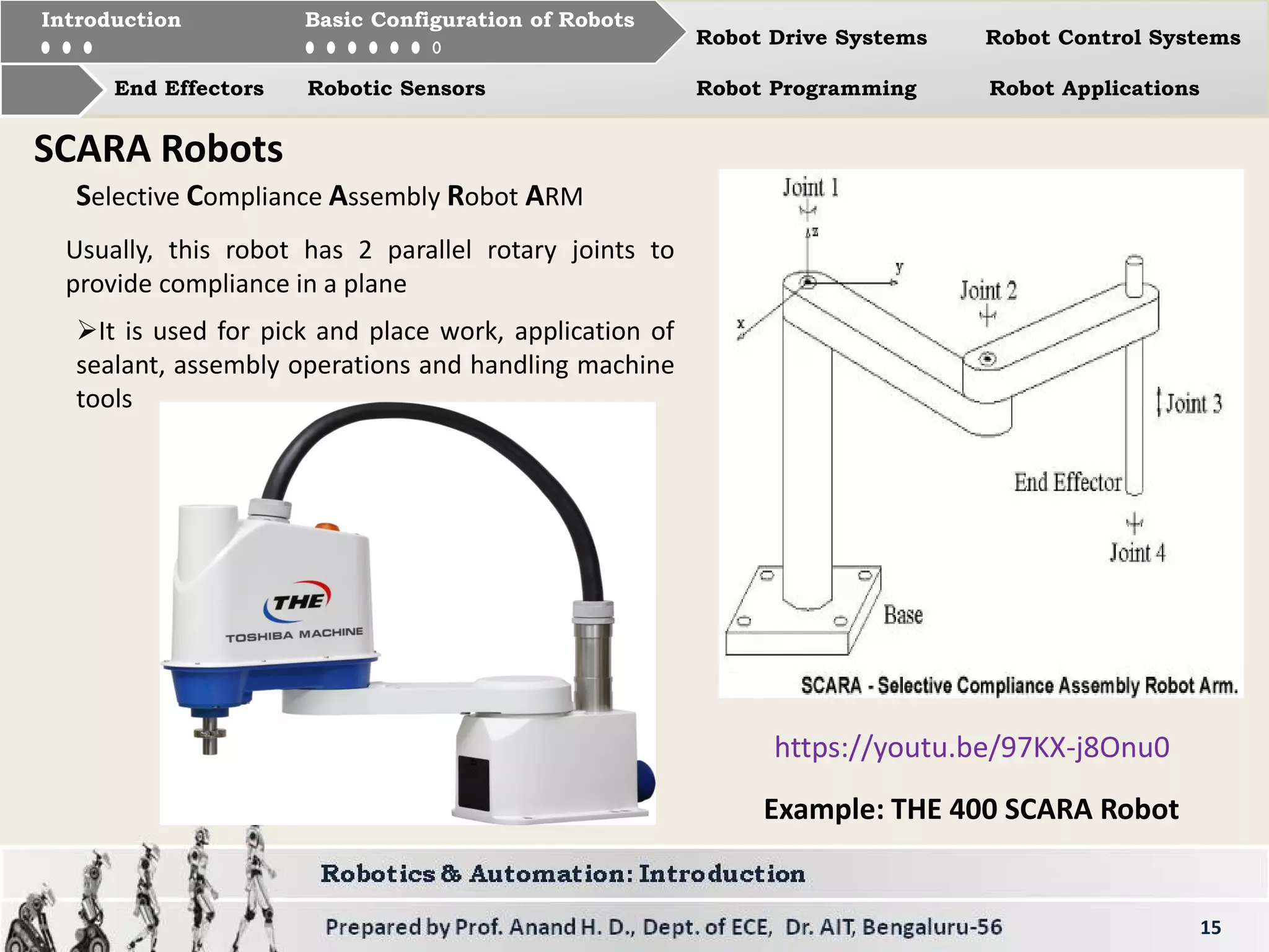
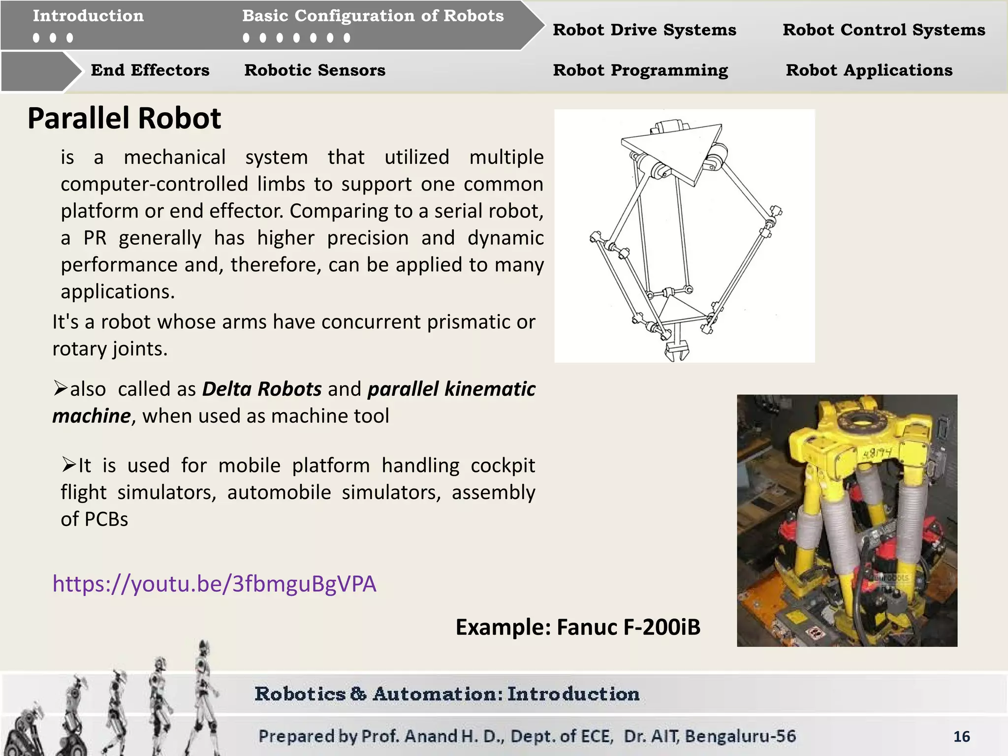
Details about SCARA robots for assembly tasks and Parallel robots, their designs, and functionalities.
Types of drive systems for robots: Hydraulic, Electric, and Pneumatic along with their uses and characteristics.
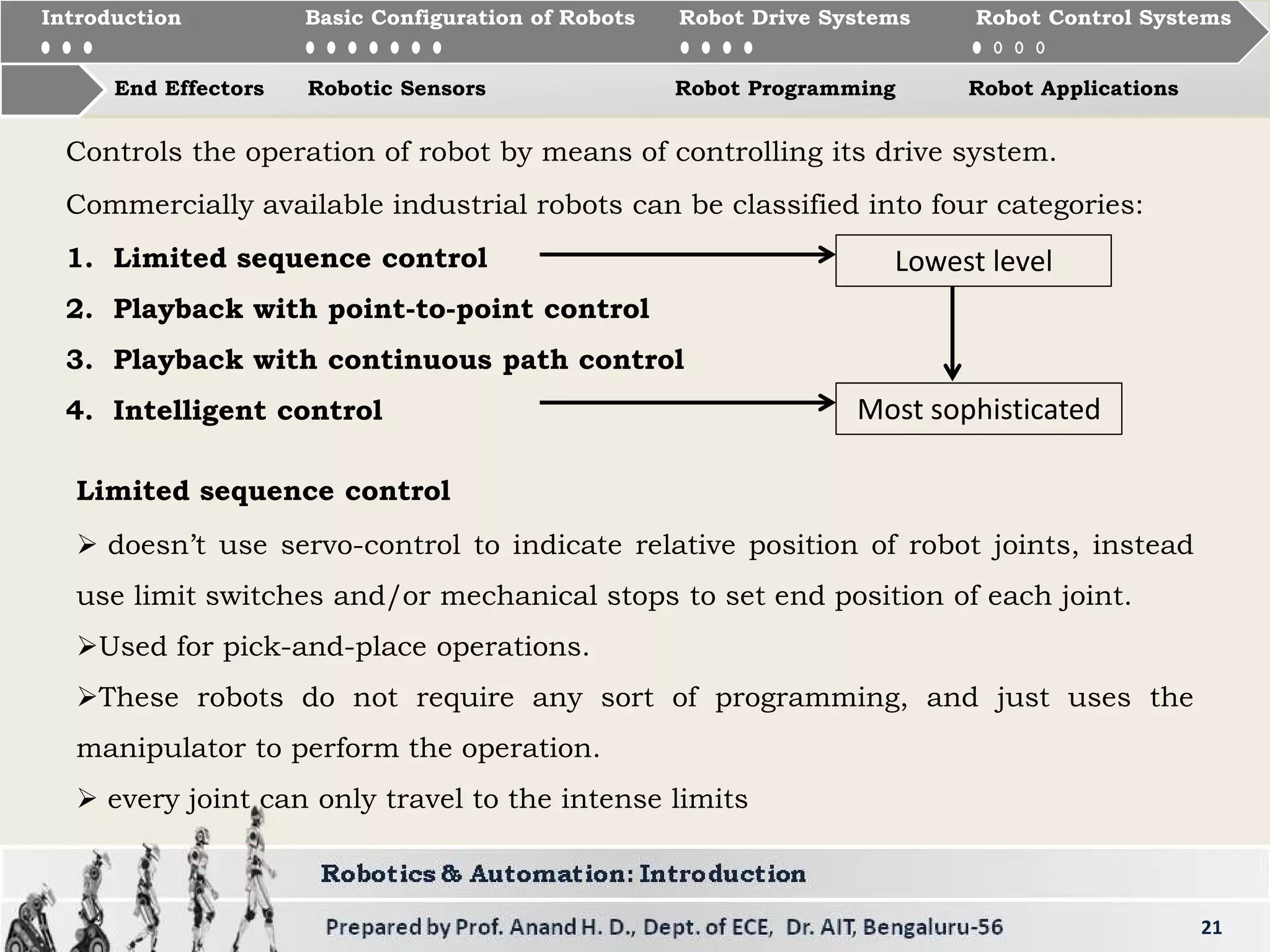
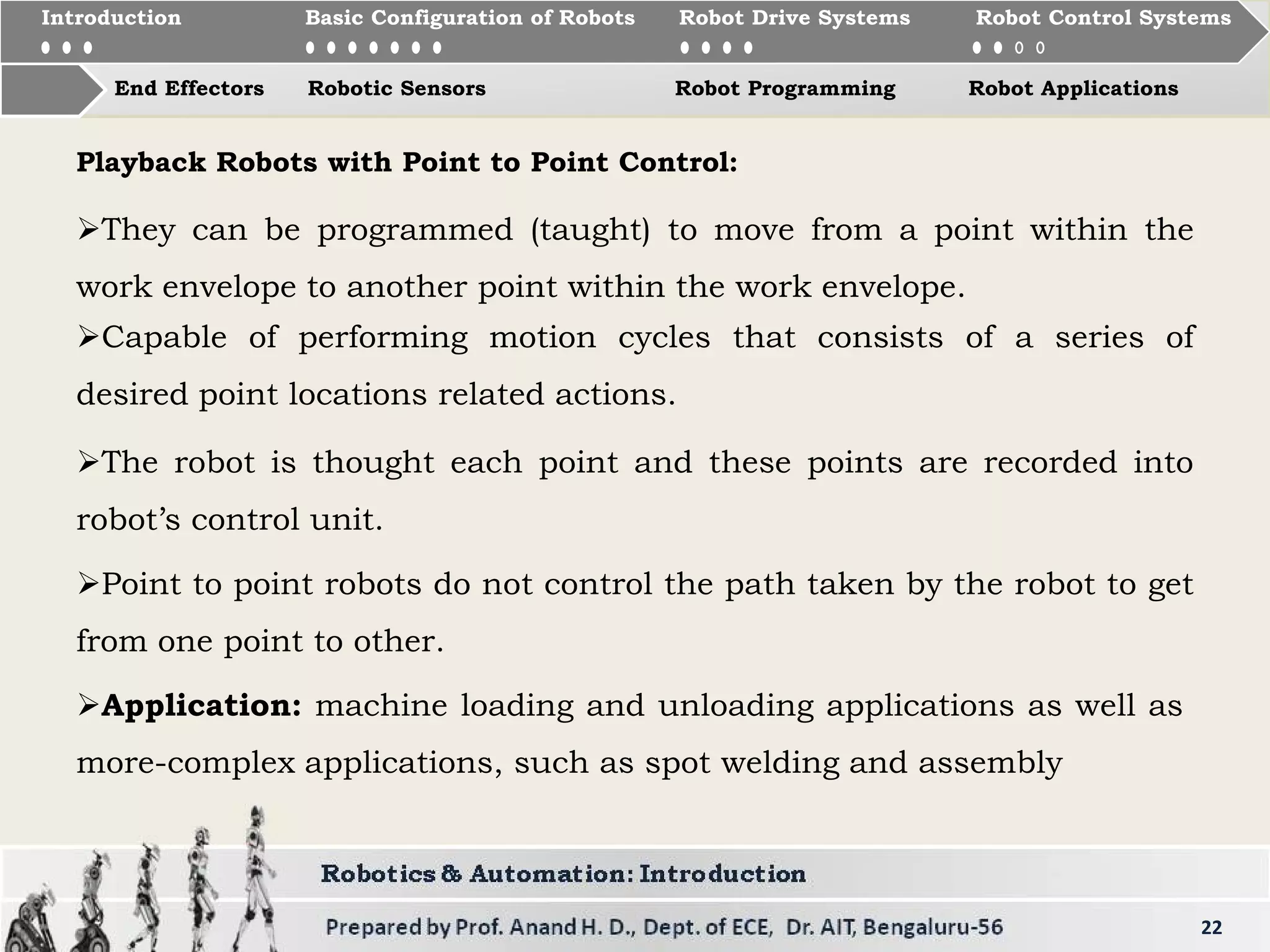
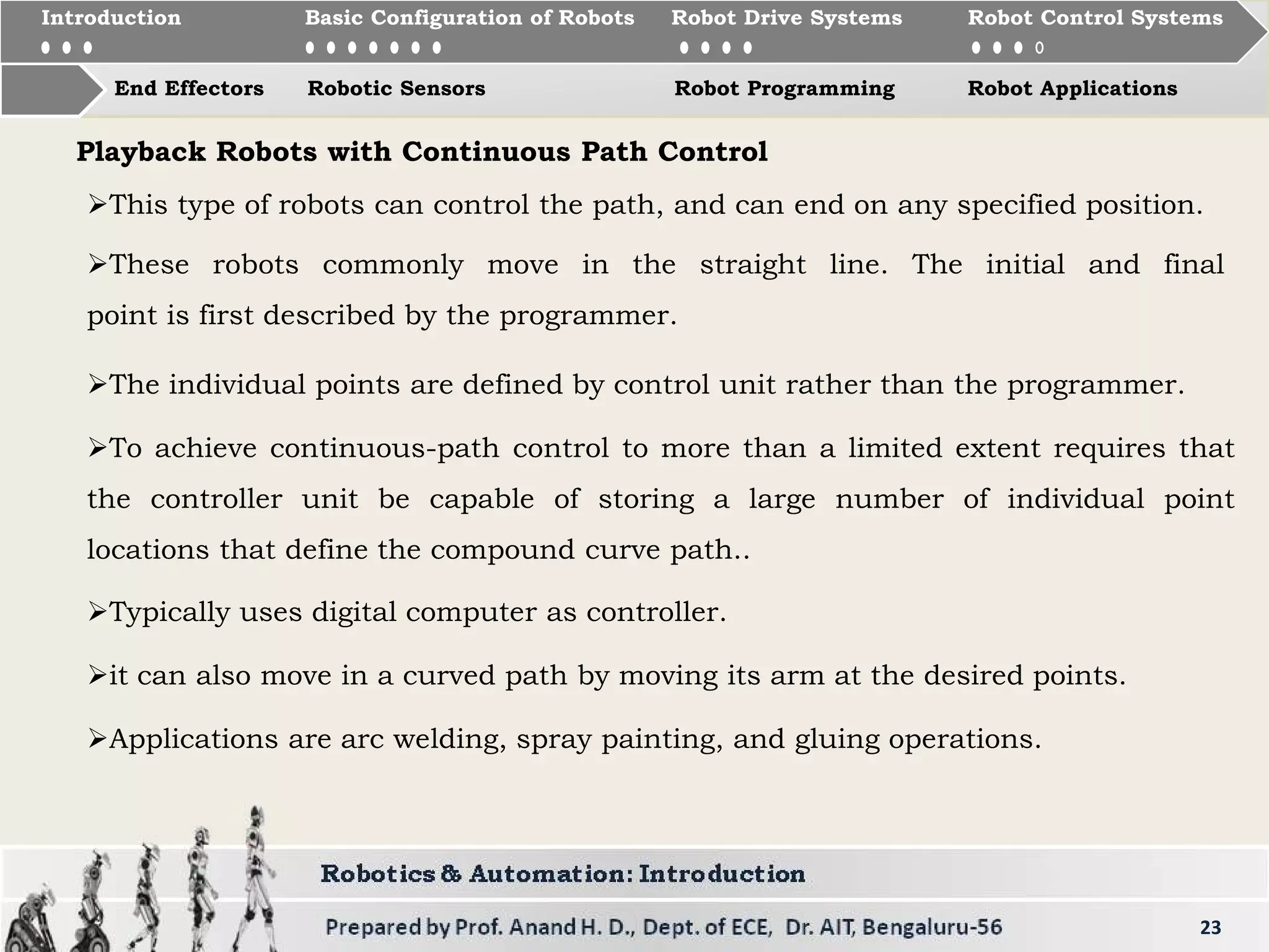
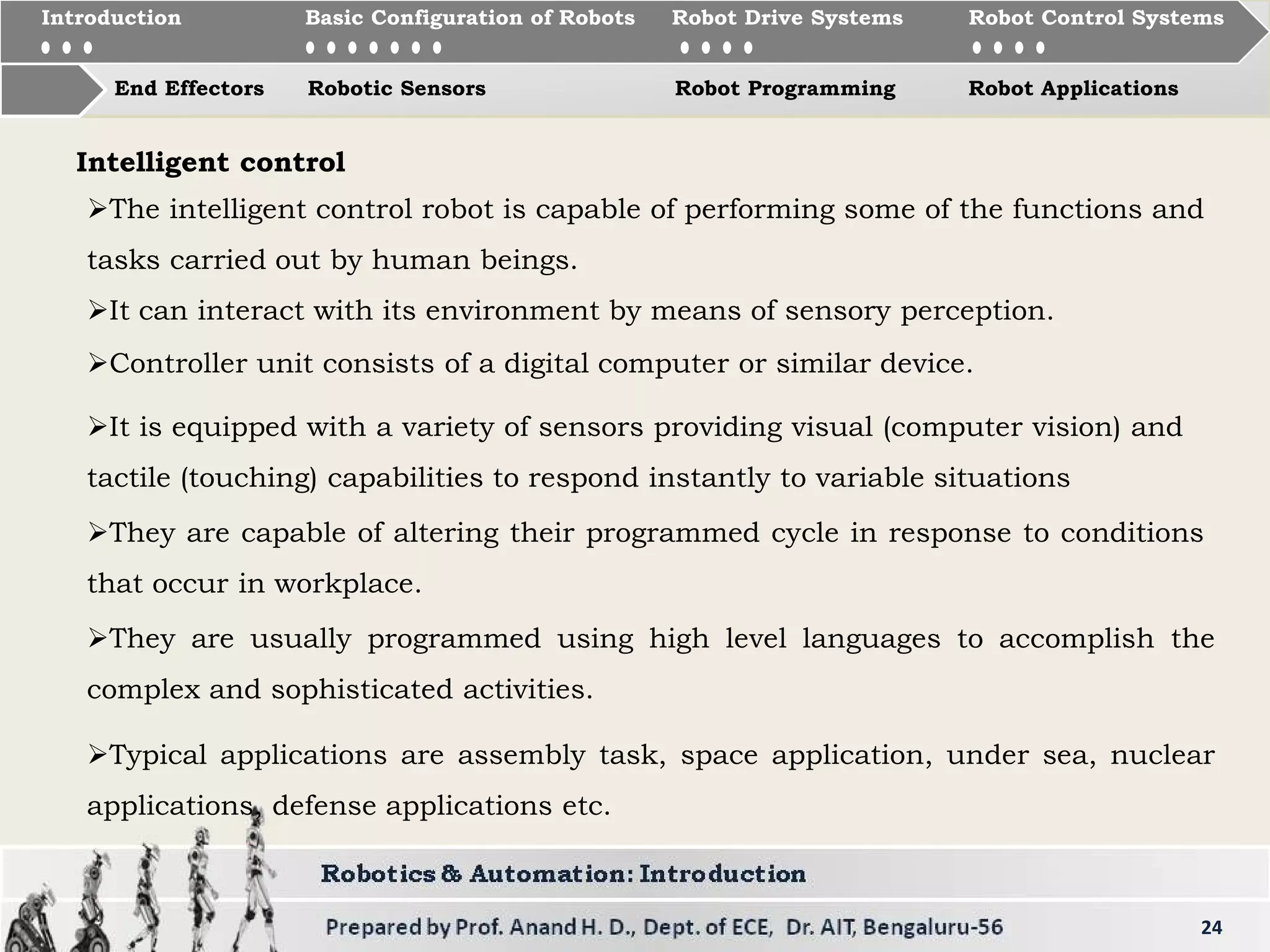
Robot drive control systems divided into four categories: Limited sequence, point-to-point, continuous path, and intelligent control.
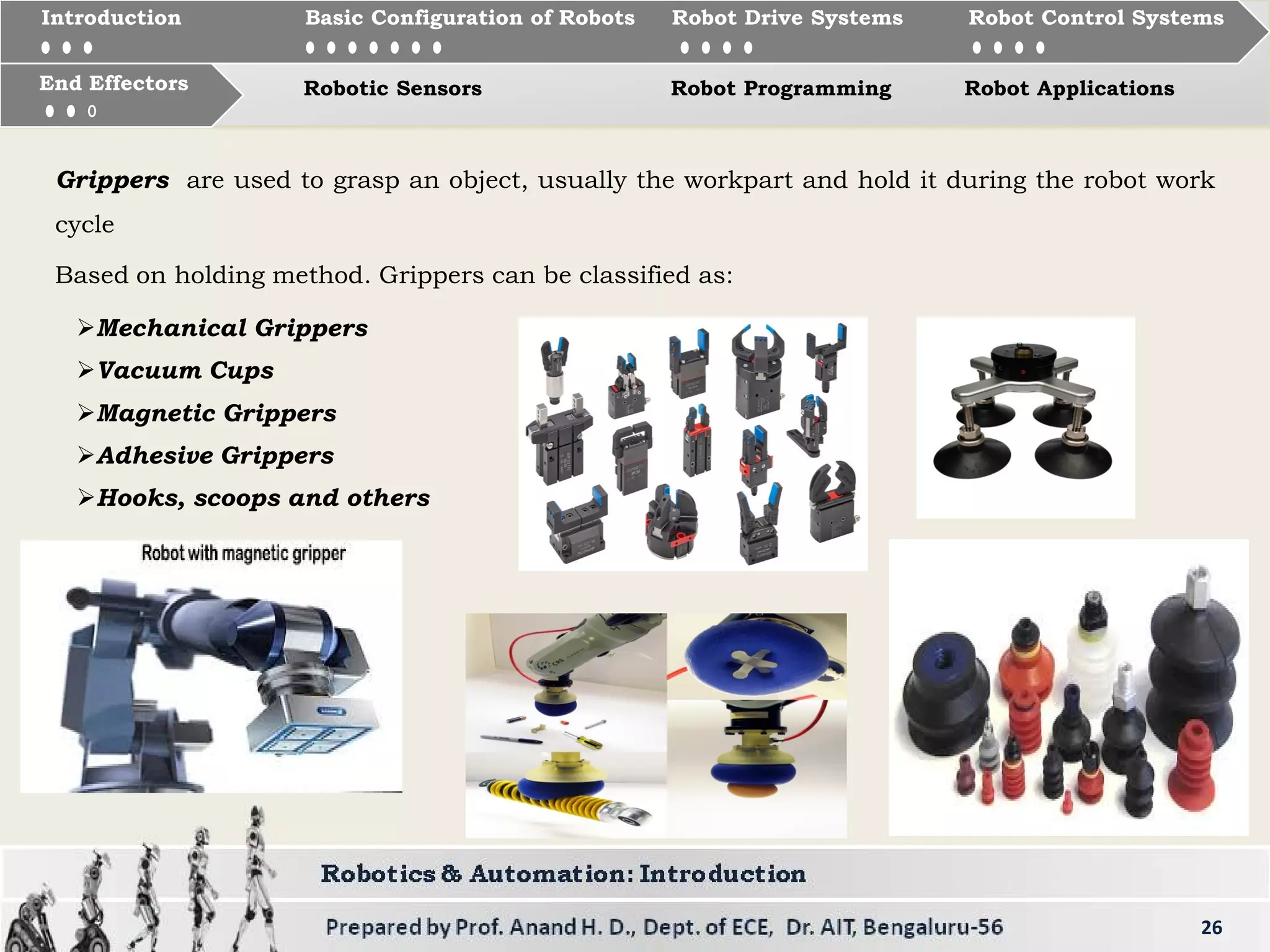
Introduction to end effectors, their types as grippers and tools, and specific applications in robotics.
The importance of sensors in robotics for environmental interaction including types like vision and internal sensors.
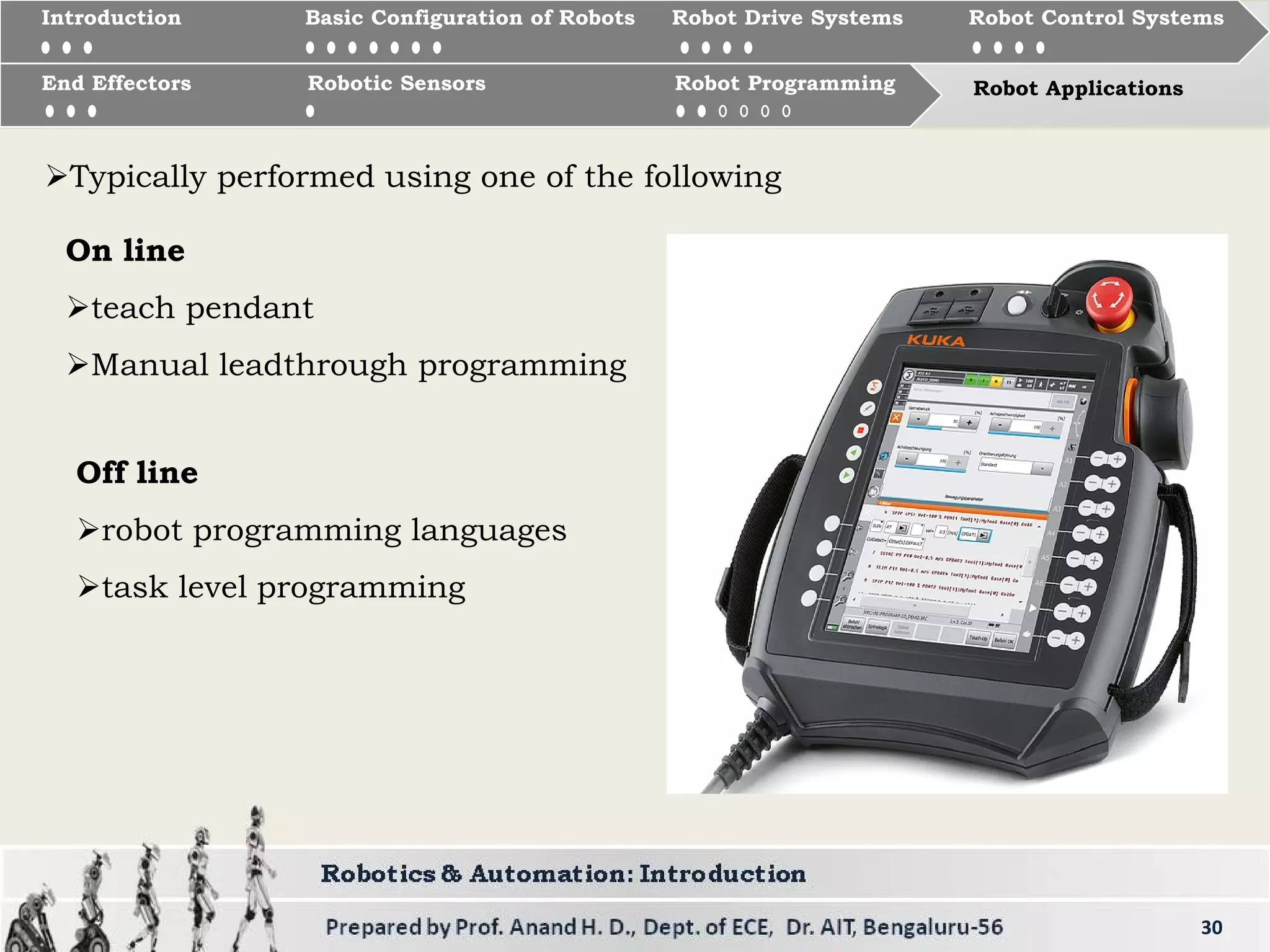
Types of robot programming methods: Joint level, Robot level, High-level, Online, and Off-line programming.
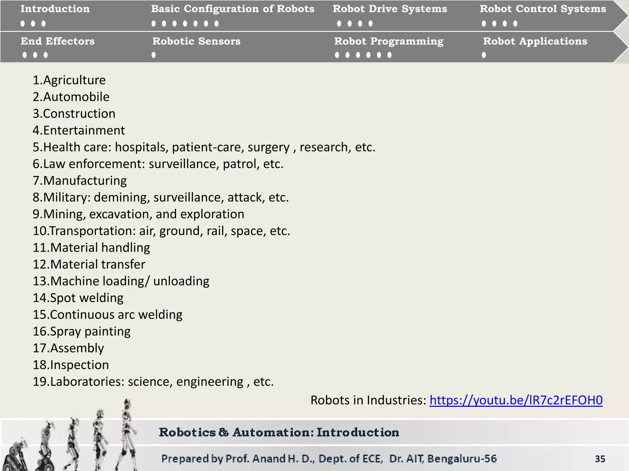
Various industries where robots are applied ranging from agriculture to military and healthcare.
Reference materials for robotics studies and additional resources including links for further exploration.