Download to read offline
![Memory Management Memories in verilog are static in nature Example :-reg[7:0] X[0:127]; 128 bytes of memory Memories are dynamic in nature Allocated at runtime Better memory management ie,queues Example:Logic[3:0] length[$]; an empty queue with an unbounded size of logic data type Verilog System Verilog](https://image.slidesharecdn.com/systemverilogveriflcation-241105143424-ea9922b9/75/SystemVerilog_veriflcation-system-verilog-concepts-for-digital-vlsi-ppt-11-2048.jpg)


![Queue… Data storage array [$] • Variable size array with automatic sizing • Searching, sorting and insertion methods](https://image.slidesharecdn.com/systemverilogveriflcation-241105143424-ea9922b9/75/SystemVerilog_veriflcation-system-verilog-concepts-for-digital-vlsi-ppt-50-2048.jpg)
![Constraint Control randomization • Values for random variable can be controlled through constraint expressions • These are declared within constraint block Class packet ; rand logic [7:0] src; rand logic [7:0] dest; Constraint my_constraints { src[1:0] == 2’b00; // constraint expression …………… // always set src[1:0] to 0 } endclass:packet](https://image.slidesharecdn.com/systemverilogveriflcation-241105143424-ea9922b9/75/SystemVerilog_veriflcation-system-verilog-concepts-for-digital-vlsi-ppt-57-2048.jpg)
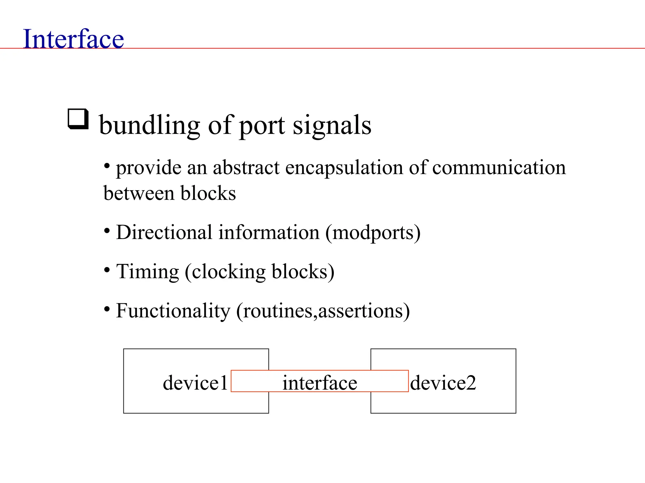
![Interface Interface bus_a (input clock); logic [7:0] address; logic [31:0] data ; bit valid ; bit rd_wr ; Endinterface: bus_a Interface:An example](https://image.slidesharecdn.com/systemverilogveriflcation-241105143424-ea9922b9/75/SystemVerilog_veriflcation-system-verilog-concepts-for-digital-vlsi-ppt-62-2048.jpg)
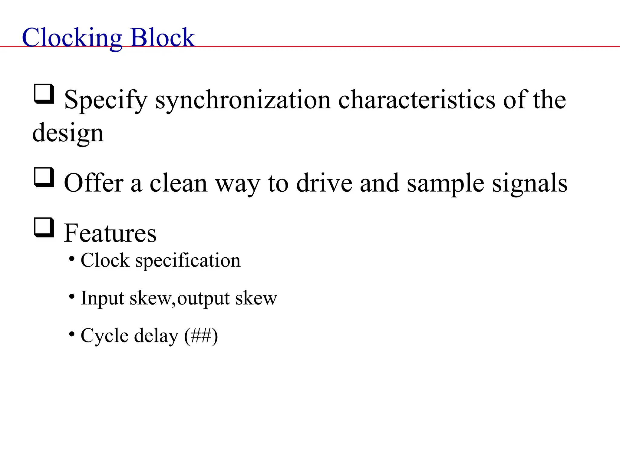
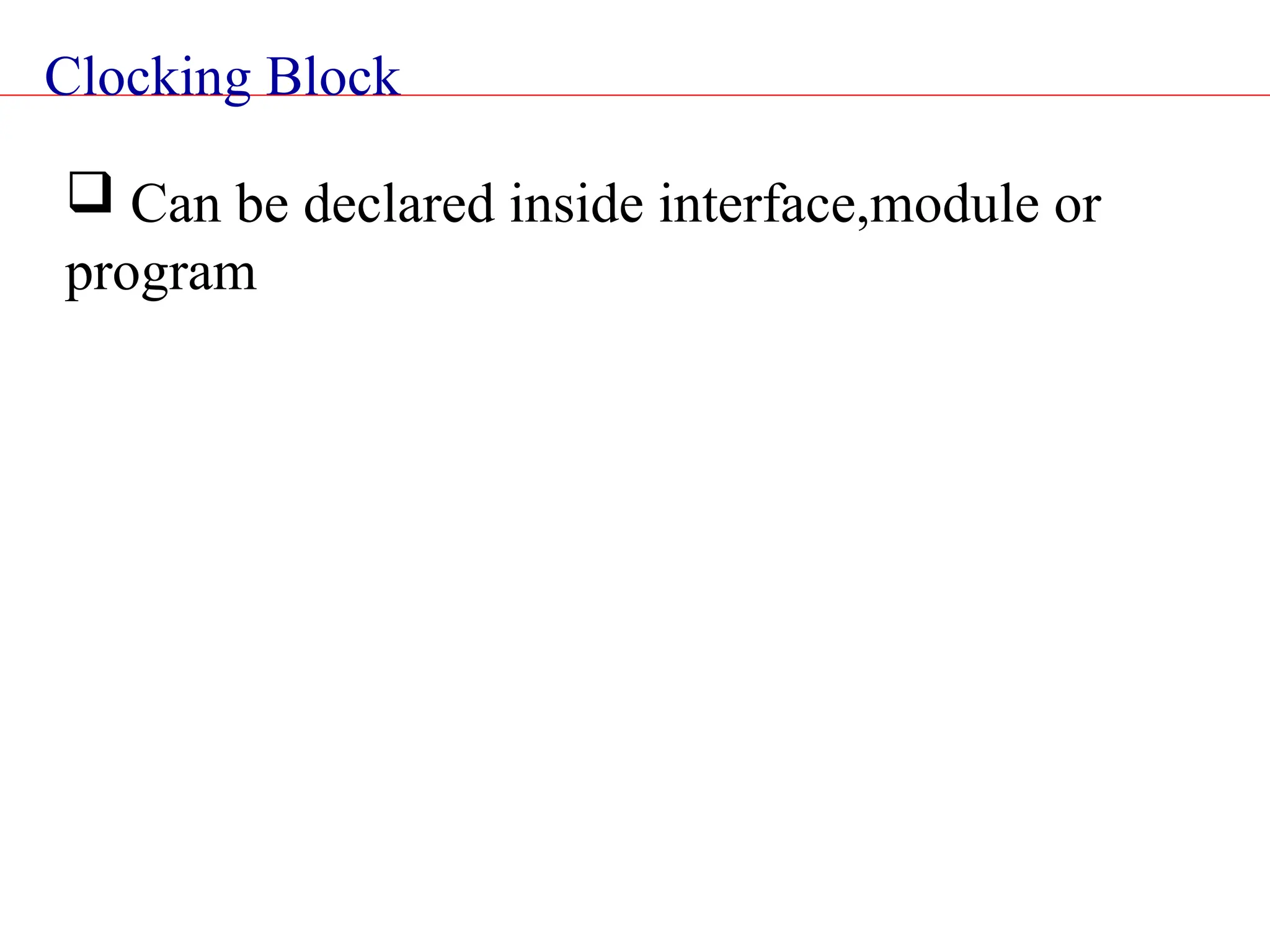
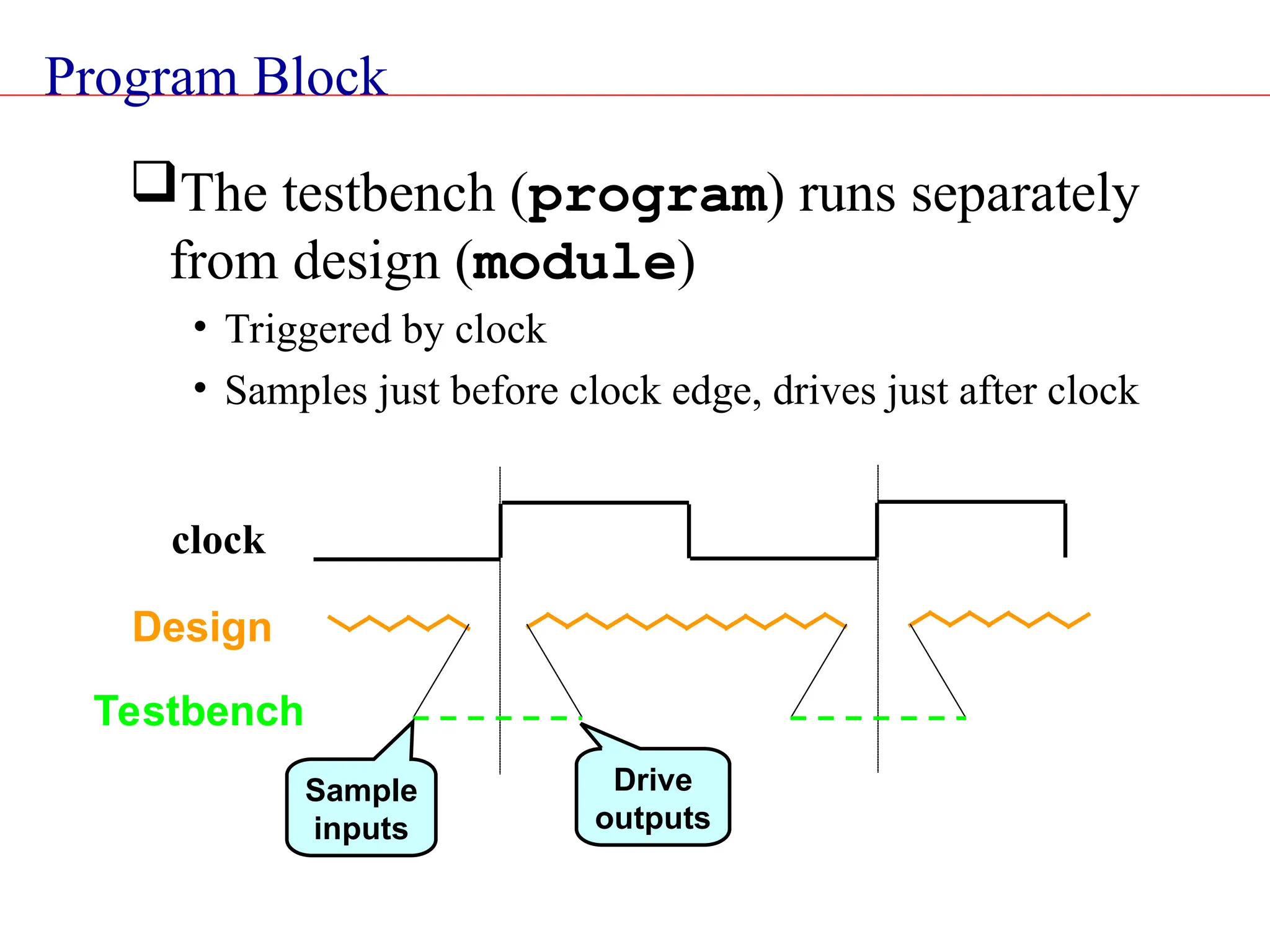
![Clocking Block Module M1(ck, enin, din, enout, dout); input ck,enin; input [31:0] din ; output enout ; output [31:0] dout ; clocking sd @(posedge ck); input #2ns ein,din ; output #3ns enout, dout; endclocking:sd reg [7:0] sab ; initial begin sab = sd.din[7:0]; end endmodule:M1 Signals will be sampled 2ns before posedge ck Signals will be driven 3ns after posedge ck](https://image.slidesharecdn.com/systemverilogveriflcation-241105143424-ea9922b9/75/SystemVerilog_veriflcation-system-verilog-concepts-for-digital-vlsi-ppt-65-2048.jpg)
![Modports An interface can have multiple viewpoints • Master/Slave, Transmitter/Receiver These can be specified using modports Interface bus_b (input clock); logic [7:0] addr,data; logic [1:0] mode ; bit ready ; modport master (input ready,output addr,data,mode) ; modport slave (input addr,data,mode,output ready) ; endinterface: bus_b All signal names in a modport must be declared in the interface](https://image.slidesharecdn.com/systemverilogveriflcation-241105143424-ea9922b9/75/SystemVerilog_veriflcation-system-verilog-concepts-for-digital-vlsi-ppt-66-2048.jpg)


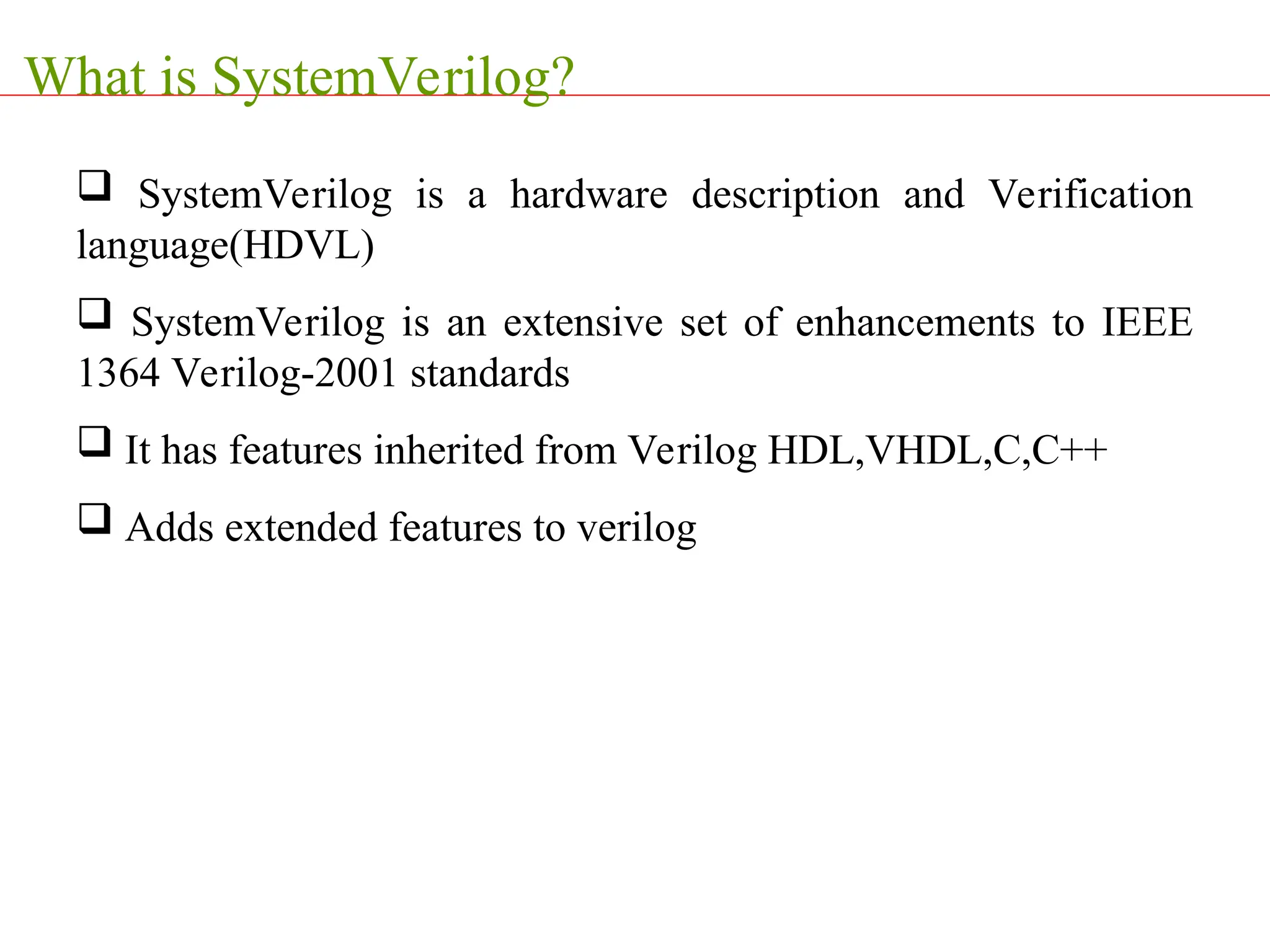
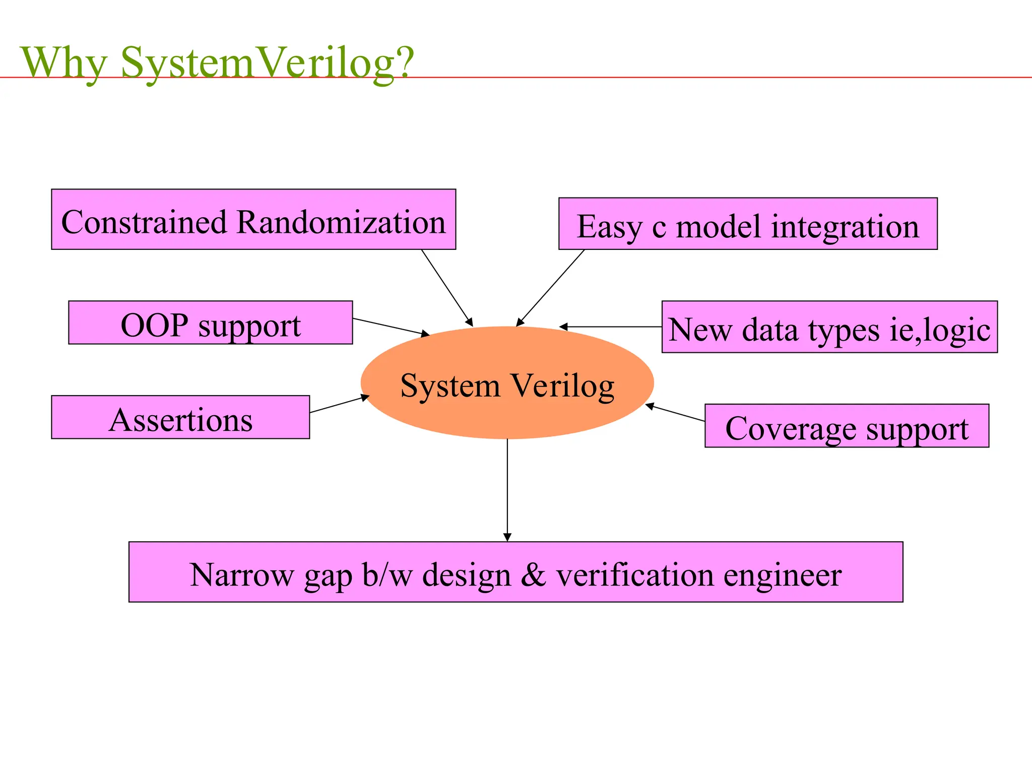
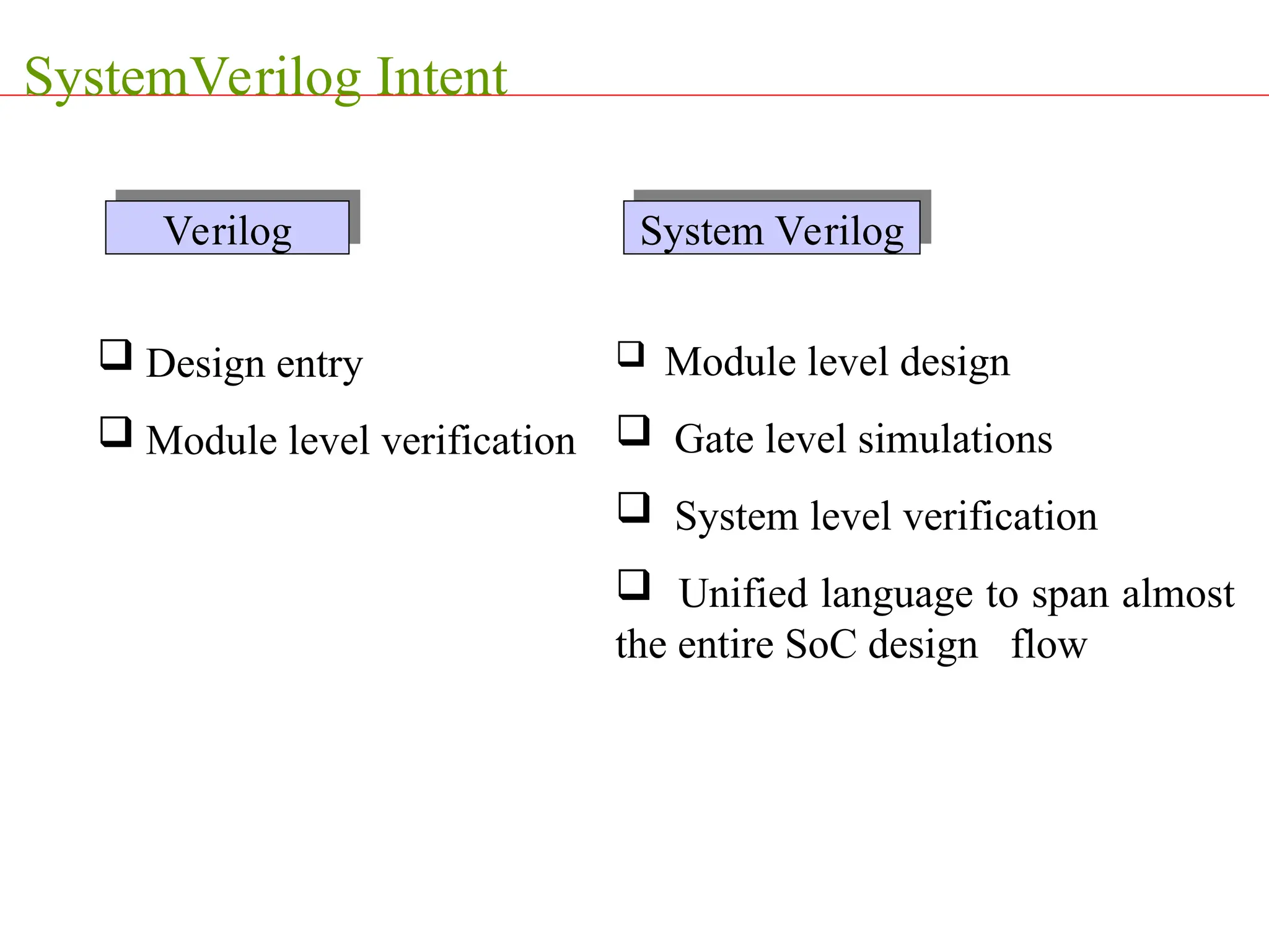
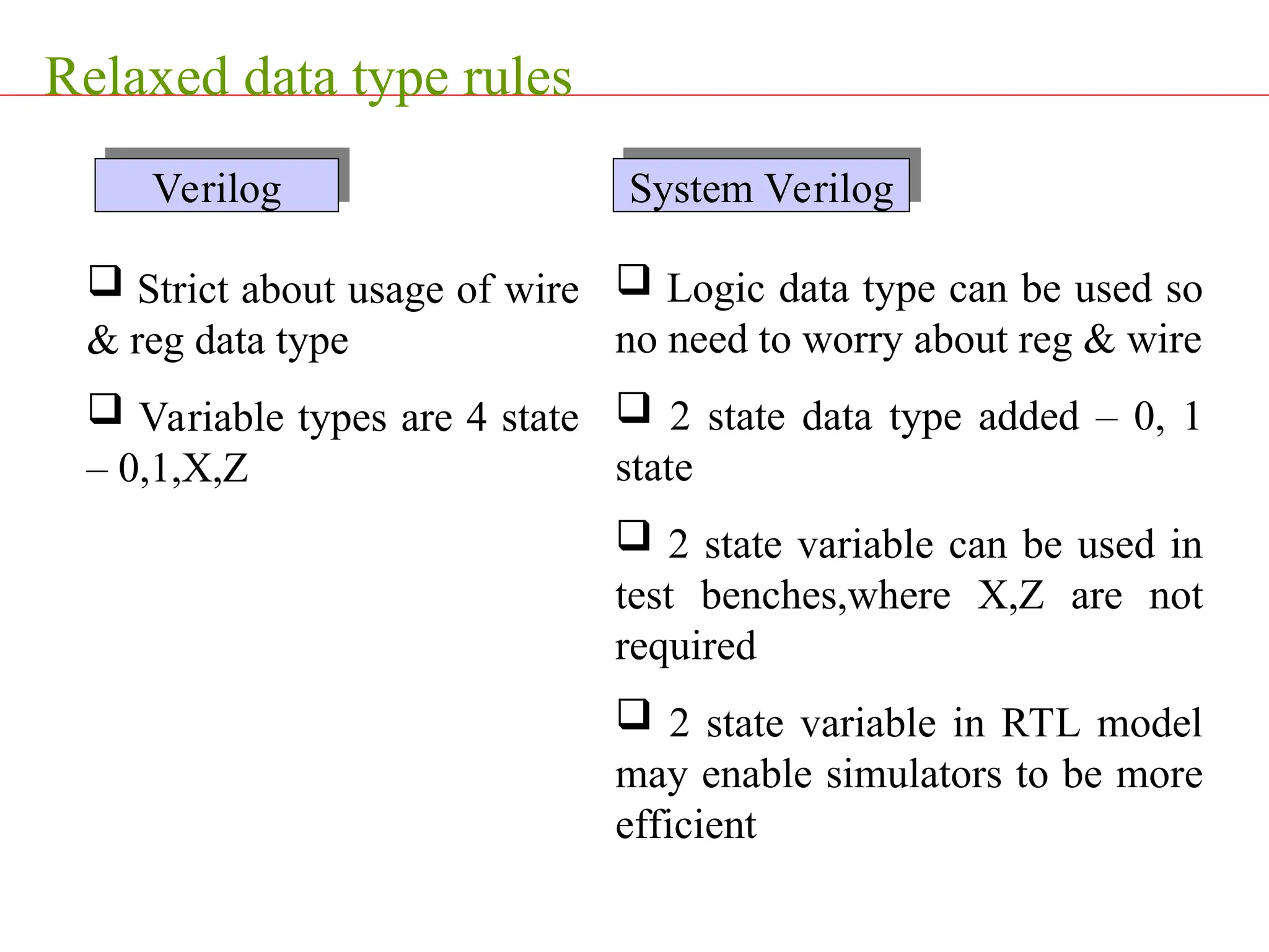
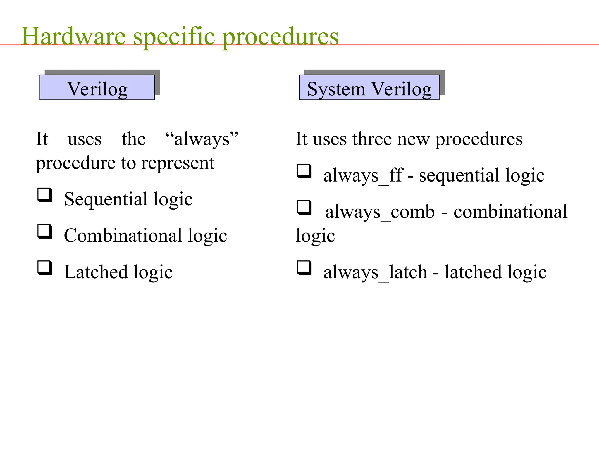
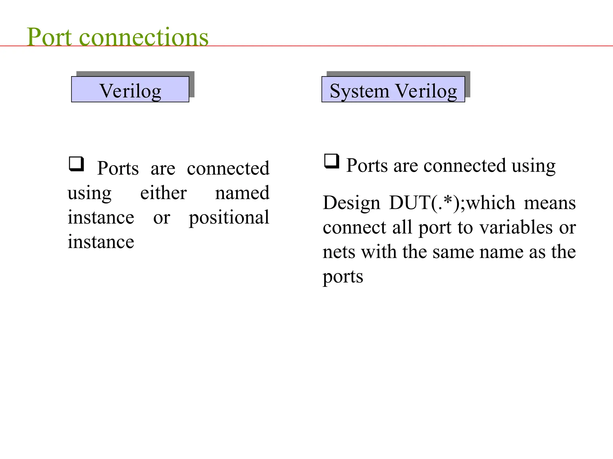
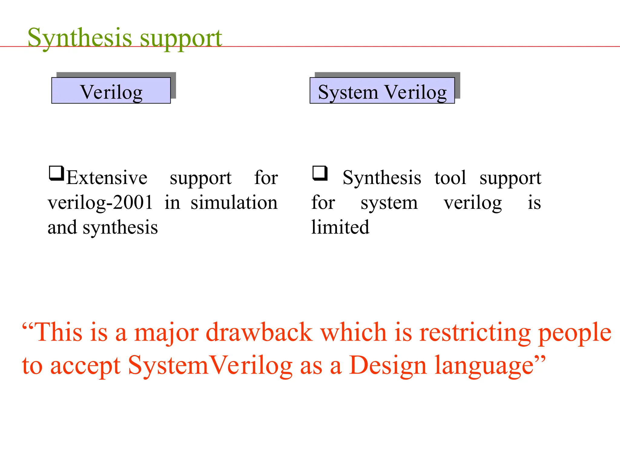
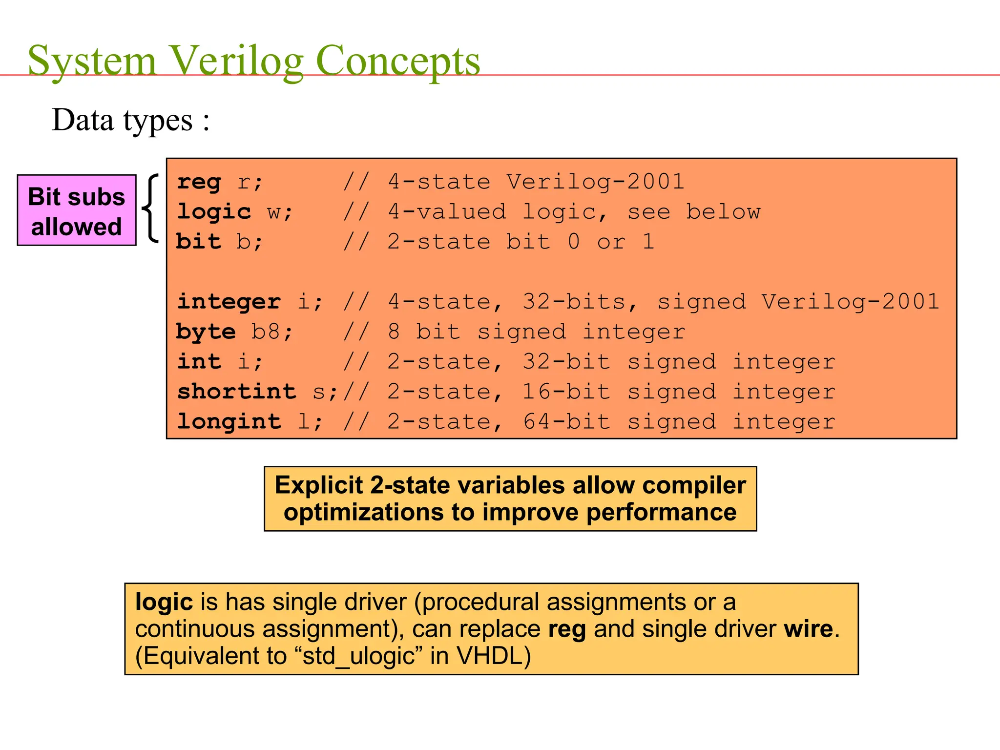
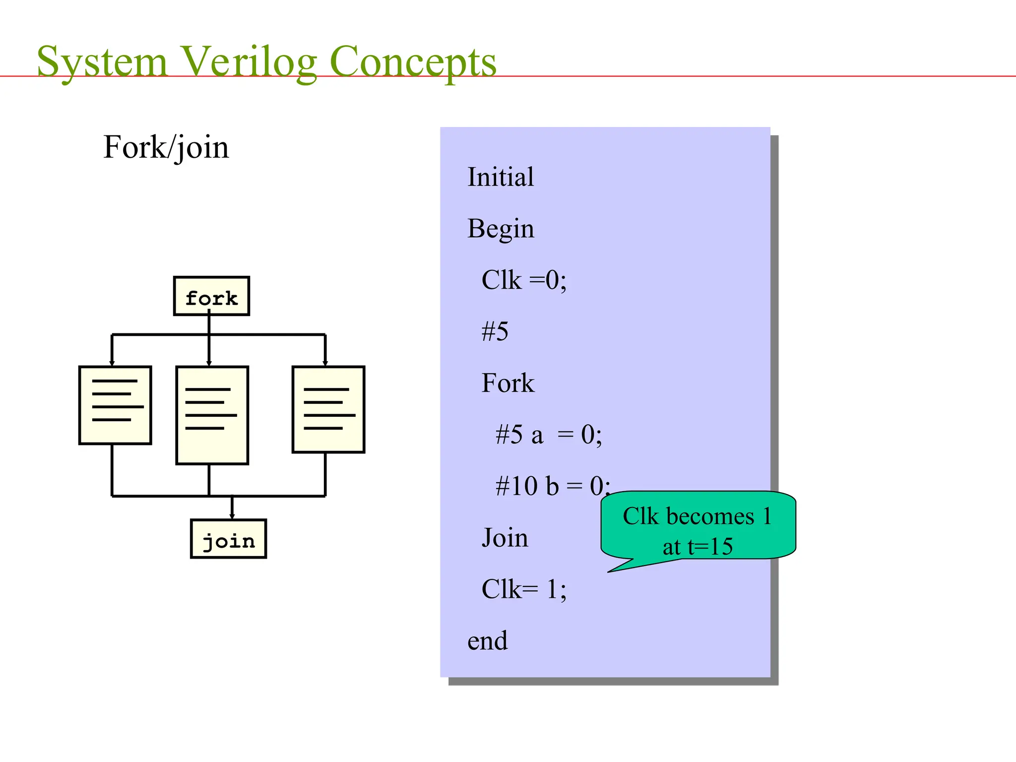
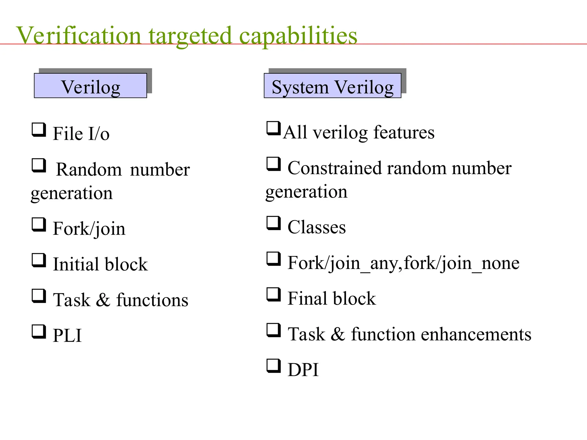
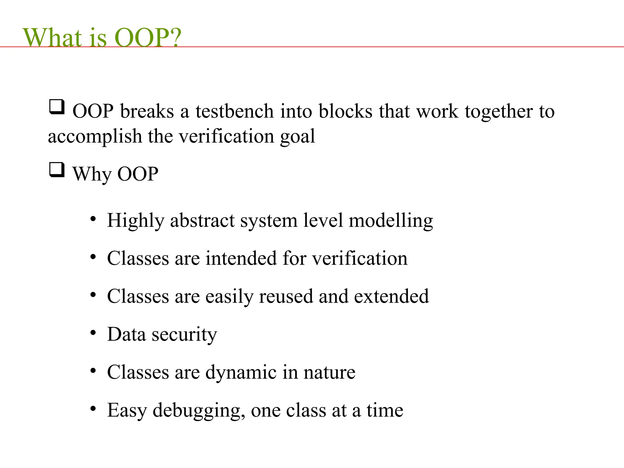
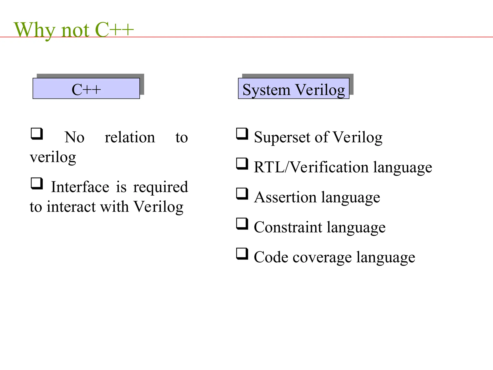
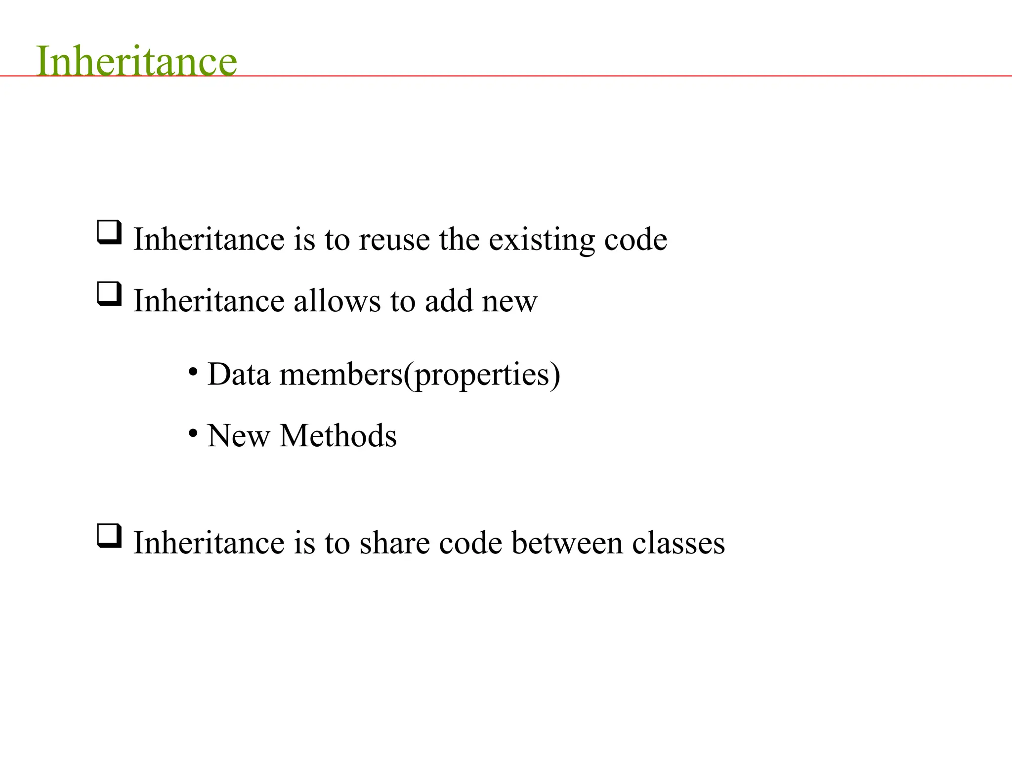
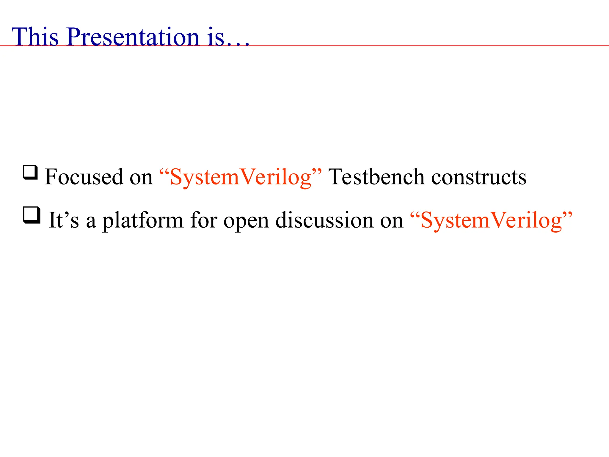
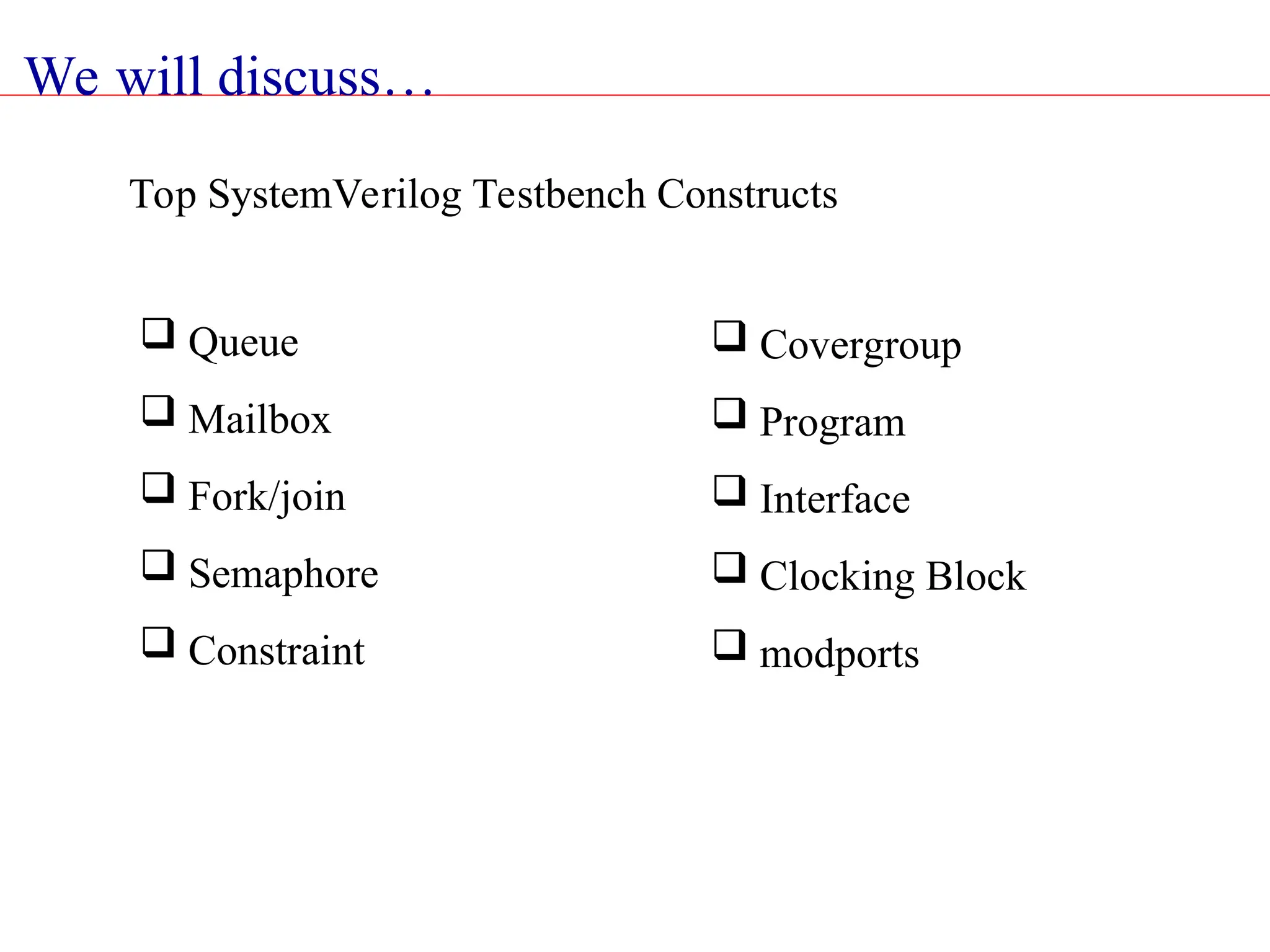
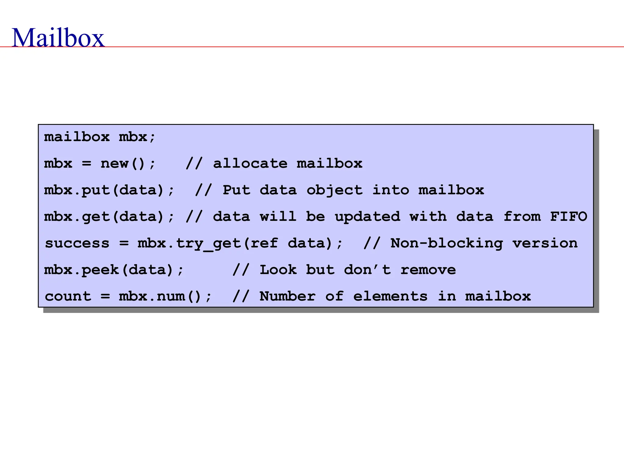
The document provides an extensive overview of SystemVerilog, detailing its features, advantages, and concepts in hardware description and verification. It highlights the differences between SystemVerilog and other languages, discusses its unified language capabilities for design and verification, and introduces key testbench constructs like queues, mailboxes, and program blocks. The presentation emphasizes SystemVerilog's role in improving verification processes through randomization, assertions, and object-oriented programming principles.