Showing posts with label minitel. Show all posts

2025-06-01

It was time for a dim bulb current limiter

One of my Minitels (the one that I modified a few years ago to run new firmware) started having power supply problems: the LED was on but nothing else was working. I suspected that the main power/CRT board needed new capacitors and so I recapped it:


Alas, despite some of the older capacitors measuring poorly compared to their specs, that wasn't the problem and so I need to go deeper. The only problem is there are a ton of nasty voltages on this board. Notably the 230V AC input and then the tens of kilovolts generated for the CRT.

Also the board seems to have a short somewhere.

So, it's time to a dim bulb current limiter. Which I didn't have. So I made one. Here it is:


It's a remarkably simple device which plugs into a standard power outlet (230V AC) and puts a lightbulb in series with one of the connections. The two wires coming in then go to a standard socket. Thus you plug your device (e.g. my Minitel) into the socket and the lightbulb limits the current.

These things were super common in the past for anyone working with mains voltages.

Works great if you have an incandescent bulb at, say, 100W. A 100W bulb on 230V AC would have a current running through it of I = V/P -> I = 100/230 (approximately 430mA). Limiting the current that way means you're less likely to damage the device you're working on if there's a short. Naturally, using a different bulb would give you a different current. 60W would give you around 230mA. 150W around 650mA. 

As the Minitel's input fuse is 630mA, my current limiter will keep things well under its blowing current. Also, if there's a complete short then the bulb will glow brightly. 

Here's a look inside:


Power comes in at the top, and goes to a DPST switch. I'm using DPST because it's not easy to know which input wire is live and which is neutral because the European Schuko/Type F plug/socket is not polarized and I like knowing that when I switch something off, it's off! And the DPST has an integrated lamp that gives me a visual reminder that it's on.


Because local power sockets aren't polarised, the power strip I am using for my bench gear uses DPST switches for each socket. It's relatively hard to find one that does this (and says it does). Thanks, Brennenstuhl!


But I digress.

To make my dim bulb current limiter do the right thing, I need a 100W incandescent bulb. These have been on their way to oblivion in the EU since 2009 and were, I believe, eliminated for home use in 2016. It is still possible to buy them, labelled for "industrial use", from some locations.
 

So, that limits the current and protects the device I'm working on, but what about protecting me? For that, I pair it with an isolating transformer. If you're not familiar with this then here's the basics. In a house the neutral line is connected to ground (typically at the point at which power comes into your house). This means that the 230V coming out the live wire is relative to ground. If I touch it the power will flow through me to ground. 

The isolating transformer eliminates the link between live, neutral and ground. It's still outputting 230V but that voltage isn't relative to ground and so I won't get a shock if I touch one of the wires coming from the transformer's socket. Of course, touching both would send 230V through me.


So, having built that I can go back to understanding why my Minitel isn't powering on.

2023-11-16

Using my Minitel 1B over the phone network in 2023

This is a story about connecting a Minitel 1B via the phone line as you would have done in the 1980s and 1990s. It's a story about enthusiastic nerds who've stood up Minitel servers that you can dial into. But it's really a story about how I hung onto French telephone adapters for more than 25 years just knowing, knowing that one day (one day!) I'd need them. 

That day was today.  


Aside: the French F-010 telephone plug is the Gallic-Telephonic equivalent of the British BS1363 three pin AC plug: when you plug it in there's no messing around.

I've written about the Minitel 1B before: using it with a fun little ESP32 gadget called the Minimit and using it as a serial terminal). But until today I had not used the internal modem to connect to a compatible server at the blinding speed of 1200/75 baud! (1200 baud down to receive data and 75 baud up to send your keystrokes).

Here's the Minitel 1B in question:


Instead of connecting it to that little Minimit box on the right I'm connecting it to my home phone line (which will for the first time in years be making a phone call!). To connect a Minitel to the phone line you need to plug it in along with a telephone. The telephone is first used to make a call to the appropriate server and then the Minitel takes over. 

So, I found my emergency telephone (and old handset I keep around for use if all I have left for communications is POTS), which for good measure has a British telephone plug on it for which I have an adapter to RJ11


I also have an RJ11 to F-010 adapter to I end up with this:


Amazingly, that works, and I can dial from Portugal into French Minitel servers. There are two in particular that seem to be online: one run by folks at IUT Auxerre and another run by enthusiast Jelora. The IUT Auxerre server is on 03 58 43 51 50 and Jelora's server is on 09 72 62 92 67. Just add 00 33 at the start and drop the 0 to dial from Portugal.

To operate Minitel you start it up and wait to see the F in the corner. Then you dial the server on the phone and wait for the modem sound. Then you press Connection/Fin and hang up. The Minitel does the rest.

Here's a warts-and-all video of me dialing in Jelora's server and then the one in IUT Auxerre. I had some difficulty with the connection with Jelora's server and given the flakiness of my cabling and the call to France I'm not super surprised.

The video should give you a good sense of the speed of operation of a Minitel in the 1980s and 1990s. And shows a typical use: getting train times (of course, you could also book train tickets). 

2023-09-09

Breathing life back into a Minitel 1B with the Minimit!

Regular readers will know that I have a lot of love for the French Minitel system and own a couple. In the past I've written about using a Minitel 1B as a terminal and replacing the EPROM in a Minitel 2 to run custom firmware. Today I'm going to blog about a project called Minimit.

The Minimit is a small, Minitel-shaped box that attaches to the Minitel's DIN port and brings the Minitel experience back to life. The box contains an ESP32 which talks to the DIN port outputting Minitel-compatible text and graphics. And the graphics and letters appear slowly just as they would have in the 1980s.

Here's my Minitel 1B connected to the Minimit (with a couple of 1980s accessories to set the scene).


On first boot the Minimit asks you to set up the WiFi configuration and make an account.


After that it's back to the 80s! Pressing the Guide button brings up a list of Minitel services.


They've built in the news from Le Monde for every day in 1983, so selecting 7 and hitting Envoi brings up Le Monde with headlines for today (September 9) but 40 years ago.


But weather information is live. Looks like a nice day in Toulouse.


And finally here's a taste of Minitel in action. Here I hit the Suite button to get the next page of headlines.


2022-10-22

Adding a mode switch to my Minitel 2

In a previous installment of me messing around with Minitels, I modified a Minitel 2 to run alternate firmware from an EPROM. This resulted in it doing things like this:


The modification worked by adding an EPROM socket to the motherboard and then pulling the EA pin on the microcontroller down to Vss to cause it to use the EPROM for its firmware rather than the firmware burnt into the microcontroller itself.

It worked in the hackiest way possible. I cut the jumper 9405 so I had access to Vcc and EA, and added a wire to Vss without even soldering it. Great for a demo but not great for longer life.


To make this more permanent I've added a switch to the bottom of the Minitel that allows selection between the EPROM and the built-in firmware.


The switch just connects EA to Vss or to Vcc via the resistor 3041.


And there you have it! (Probably) the world's Minitel 2 that can switch between internal and external firmware. Pity I'm 29 years late.

2022-04-02

Setting up and running the MAME emulation of the Minitel 2

In a previous post I showed how I modified a Minitel 2 to run arbitrary firmware. The firmware I used came from a chap who has played around with Minitel 2s quite a bit. And, as I said in that previous post, I want to write my own firmware. 

My original plan was to write the firmware and use the Dataman S4's emulation capability to avoid having to burn EPROMs for each build. But the aforementioned chap has made things even easier by creating a Minitel 2 emulation in MAME.

If you download MAME you'll find the Minitel 2 included as a standard machine:


Naturally, you'll need some ROMs. The Minitel 2 emulator in MAME knows about three ROMs: minitel2_bv4.bin (which is the BV4 version of the original firmware), bv9.1402 (the BV9 original firmware; that's the one my actual Minitel 2 had burnt into the CPU) and demo_minitel.bin (which is the demo ROM I used in the previous post). You also need charset.rom which contains the character set for the Minitel.

You need to find these. I got them by searching for "bv9.1402 minitel" and found them here

Here are the steps I took to get MAME + Minitel2 running on my Mac. Initially, I figured I'd use brew but ran into some random errors and I'm too old to fight package managers. So, I switched to using the instructions on the main MAME website.

For the Mac, MAME runs using a thing called SDL and details are here. You first need to install SDL (Simple Directmedia Layer) from here.


The .dmg doesn't open with an installer, but the ReadMe.txt has the instructions:

    To Install:
    Copy the SDL2.framework to /Library/Frameworks

which I did. After that you can download MAME itself. It's a simple ZIP file that expands into a directory:

$ pwd
/code/mame0241-x86
$ ls
COPYINGctrlrimgtoolldverifyromcmp
artworkdocsinimameroms
bgfxfloptooljedutilnltoolsamples
castoolhashkeymapsnlwavuismall.bdf
cfghistorylanguagenvramunidasm
chdmanhlslldresamplepluginswhatsnew.txt

I mentioned above the need to install the Minitel 2 ROMs. They go into the roms directory (highlighted above) in a subdirectory called minitel2.

$ ls -R roms
dir.txtminitel2

roms/minitel2:
bv9.1402demo_minitel.bin
charset.romminitel2_bv4.bin

At which point you can simply start MAME. If you start it with just ./mame it seems to take over the entire screen on the Mac and is very hard to exit. Better to start with the -window option which will open it in a desktop window (see the screenshot above).

./mame -window

Then scroll down to Minitel 2 and double click on it. This will pop up a menu of available ROMs:


The Bv9 and BV4 ROMs are the standard Minitel 2 firmware and Minitel 2 Demo is Del Nero's demo firmware that I used in a previous post. Here's what it looks like running in MAME:


If you run the standard Minitel 2 firmware ROMs they start with the machine powered off (the real Minitel would need its power button pressing to start). The MAME implementation maps the following function keys on the Mac to special keys on the Minitel 2 keyboard.

    F1         ->     Suite
    F2         ->     Retour
    F3         ->     Envoi
    F4         ->     Repetition
    F5         ->     TEL
    F6         ->     Guide
    F7         ->     Sommaire
    F8         ->     Connexion/Fin
    F9         ->     Fonction
    F10        ->     On/Off

So, pressing Command-Fn-F10 on the Mac will start the standard firmware:


Finally, if you are interested in writing your own Minitel 2 firmware MAME's debugger is very useful and can disassemble the running ROMs and allows single stepping etc. Start it with ./mame -window -debug minitel2.

This will bring up the main MAME window and a debug window like this:

2022-03-26

Voiding the warranty on a 1993 Minitel 2 to run arbitrary firmware

In a previous post I wrote about using a Minitel 1b as a serial terminal. In this post I'm going to look at modifications I made to a Minitel 2 so that it can run arbitrary firmware from an EPROM. If you speak French, or are happy with automatic translation, then Jean-François Del Nero's post on the workings of the Minitel 2 is a good place to start. At the end of this post I will be running his Minitel 2 demo firmware on my Minitel 2. 

He plays some neat tricks with the Minitel's character-based video to fake up graphics like this:

Inside the Minitel there are two boards: one dedicated to the input power and handling the CRT (that's the vertical board on the left) and a motherboard with the 8051-based CPU, modem, video controller, etc. Since CRTs use high voltages and there are some big capacitors on that board I'm staying away from it for the entirety of this hack.

Dude, where's my EPROM?

Here's the motherboard of my Minitel 2. I've marked up the major chips. If you take a look at Del Nero's post you'll see that he replaces the EPROM containing the standard Minitel firmware with his own code. But, alas, my Minitel doesn't have an EPROM at all!


But you can see the place where a 40 pin socket would have been had this model used an external EPROM. In my Minitel, the firmware (with code name BV9 written on the top of the chip in the same as the BV9 on Del Nero's actual EPROM; I guess by the time mine was built they were pretty confident about the firmware) has been burnt directly into the microcontroller CPU. 

I thought for a while that I might be stuck, but careful examination of the PCB showed that all of the traces were in place for that socket.


And reading the CPU's datasheet showed that whether it executed code from the internal ROM or external ROM was dependent on the state of the EA pin on the CPU. 


Looking at the motherboard I could see that EA is pulled to Vcc via the resistor 3401 and wire 9045. Since I'm obsessed with double-checking things I went back and looked at Del Nero's motherboard and that resistor and wire are in place. Hmm. What's pulling EA down to Vss then? 

Luckily, another Minitel fanatic whose Minitel 2 posted a picture of the reverse side of their motherboard.


On that motherboard there's a surface mount, zero ohm resistor (i.e. a wire) that connects EA to Vss (it's still connected to Vcc as well but through a resistor).

OK, so it seems pretty obvious to me that if I removed the solder pads from where the 40 pin socket was meant to go, added a socket, burnt a suitable EPROM and pulled EA down to Vss I'd be able to run external firmware on EPROM.

A small matter of soldering


First step, was add a socket:


The next step was to pull down EA. I choose (unnecessarily) to cut 9045 and separate the Vcc and EA lines. I was originally planning to use Vcc for something else. If you do this then you could just connect 9045 to Vss and be done with it. 

Making the EPROM


Then I took Del Nero's firmware from GitHub and burnt it onto a suitable EPROM. The Minitel uses a shared address/data bus and thus the EPROM needs to latch the address and so "standard" EPROMs don't work. Luckily, the 87C257 is readily available and programmable using my Dataman S4.

I wrote a couple of tools to perform the Dataman S4 checksum and to turn a binary file into an Intel HEX format for the Dataman. Del Nero's file is demo_minitel.bin and I first checksummed it so that later I could double check on the Dataman.

target/debug/s4checksum < /tmp/demo_minitel.bin
00289F61

Next up, I converted it to an Intel HEX file.

cat /tmp/demo_minitel.bin | target/debug/bin2intel > /tmp/demo_minitel.hex

And then uploaded it to the Dataman S4 via miniterm.py. There are a lot more details of operating the Dataman S4 in my previous post.

--- Available ports:
---  1: /dev/cu.BLTH         'n/a'
---  2: /dev/cu.Bluetooth-Incoming-Port 'n/a'
---  3: /dev/cu.URT1         'n/a'
---  4: /dev/cu.URT2         'n/a'
---  5: /dev/cu.usbserial-1460 u'USB-Serial Controller D'
--- Enter port index or full name: 5
--- Miniterm on /dev/cu.usbserial-1460  9600,8,N,1 ---
--- Quit: Ctrl+] | Menu: Ctrl+T | Help: Ctrl+T followed by Ctrl+H ---
 
--- Enter new encoding name [UTF-8]: ASCII
--- serial input encoding: ASCII
--- serial output encoding: ASCII
 
--- Settings: /dev/cu.usbserial-1460  9600,8,N,1
--- RTS: active    DTR: active    BREAK: inactive
--- CTS: inactive  DSR: inactive  RI: inactive  CD: inactive
--- software flow control: inactive
--- hardware flow control: active
--- serial input encoding: ASCII
--- serial output encoding: ASCII
--- EOL: CRLF
--- filters: default
>RECEIVE INTEL   
--- File to upload: /tmp/demo_minitel.hex
--- Sending file /tmp/demo_minitel.hex ---
.........................................................................................
--- File /tmp/demo_minitel.hex sent ---
 
EOF 07FFF
>CHECKSUM RAM
00000,07FFF 
SUM = 00289F61
>

The Dataman needs to know the PROM type which you select through the PROM button.


And naturally you need to insert a blank EPROM.


Good news is that the checksum of the uploaded file matched the checksum of the binary file. Next step was to burn a blank 87C257. First made sure it was burnable.

>PRETEST 87C257
 00000-07FFF=00000
BLANK ROM
>

Then hit the BURN button on the Dataman S4 and let it do its thing.


Finally, checksum the EPROM itself to make sure its correct.

>CHECKSUM RAM
00000,07FFF 
SUM = 00289F61
>CHKSUM 87C257
SUM = 00289F61

Looks good, so I popped it in the Minitel, used a wire to pull EA down to Vss and switched it on. Amazingly, it worked first time.

It's alive!


Do not operate the Minitel with the case open, there are nasty voltages on that CRT. I always slipped the cover back on before doing this, but here's what it looks like with the EPROM in situ:


And here's what that firmware does. 


And, uh, sorry France Telecom I think I might have voided the warranty.


Next time, I'll start writing my own firmware using the Dataman's emulation mode and see what writing for this machine is like. One quirk is that the 8k of RAM is accessible to the video controller and not the CPU. Well, not directly, you can access it through the video controller... can I get this machine to run BASIC-52?

And I'll add a small switch to the Minitel so the user can choose internal ROM (original) firmware or external (custom) firmware.

2022-03-20

Using a Minitel 1B as a serial terminal

So you've got your hands on a late 1980s Minitel 1B (or something slightly later) and then you realize that the entire Minitel network shut down in 2012. What do you do? Well, obviously, you recall that the Minitel 1B (and other later models) have two modes of operation: using the modem to connect to the Minitel service or as a serial terminal via the "peri-informatique" port. With the latter you can use the entire thing as a serial terminal and connect it to something (such as a Raspberry Pi) and browse the web.

Note: there are other interesting modes (such as peer-to-peer Minitels) but I won't go into that here.

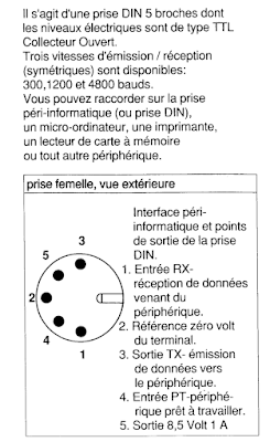
The peri-informatique port on the back of the Minitel is a five pin DIN socket which supports open collector TTL logic levels with up to 4,800 baud serial (later models supported faster transmission).


The pinout (note the ordering!) is pin 1 (RX), pin 2 (0V reference), pin 3 (TX), pin 4 (ready) and pin 5 (8.5V at 1A). With just three pins (1, 2, 4) it's pretty easy to put together a cable that turns the Minitel into a serial terminal.

And since the Minitel has an ASCII mode it'll work pretty well outside of its original Videotex format with the right combination of keys. It's important to have a Minitel with the FNCT key because it controls a lot of settings.

Note: if you speak French you can just skip the rest of my explanation and go and read Un minitel comme terminal linux USB. Partie 1 : Hardware because in this post I build and try out precisely what that blog recommends.


A simple test


A quick way to test that your Minitel is happy being in peri-informatique mode is to connect TX to RX in the DIN socket and see if characters get echoed to the screen. I did this with a small piece of paper clip connecting pin 1 (RX) to pin 3 (TX).


By default the peri-informatique port is active and so anything typed is sent out of it, and anything received is displayed. I like to set the display mode to US ASCII with FNCT+T followed by A (if you want a French version of ASCII use FNCT+T followed by F).

If you start typing you should see everything you type twice: once because you typed it and the Minitel echoed it and once because it got sent and receive through the piece of paperclip. To turn off local echo and just see what went from TX to RX, it's FNCT+T then E.

Assuming that worked then you're in good shape to turn this simple serial port into something that can be plugged into USB. For that you'll need a USB-to-serial adapter, three resistors, one transistor and a plug for the DIN socket.


USB-to-Minitel Cable


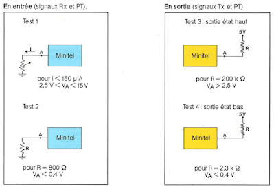
Before getting to the USB part of the connection it's worth taking an excursion through the details of the Minitel's serial port. The official documentation describes it as "compatible with TTL open collector" logic and gives the following constraints:


Firstly, we learn that logic level 0 is below 0.4V and logic level 1 is above 2.5V (and below 15V). If you look at the RX diagram on the top left you can see that when receiving a logic 1 (voltage greater than 2.5V) current may flow from the Minitel and should be below 150uA. You might be asking yourself why the receive signal would be a current source. That's standard TTL logic style.

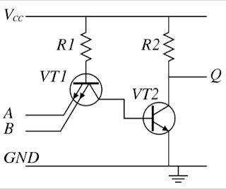
In TTL logic inputs are typically the emitter of a transistor. Here's a simplified TTL NAND gate. Notice how the inputs are emitters in a special double-emitter transistor.


Imagine the case where A and B are tied to ground (logic 0): current will flow through VT1 across the base-emitter junction and therefore out A and B. So, an input is a current source when driven low.

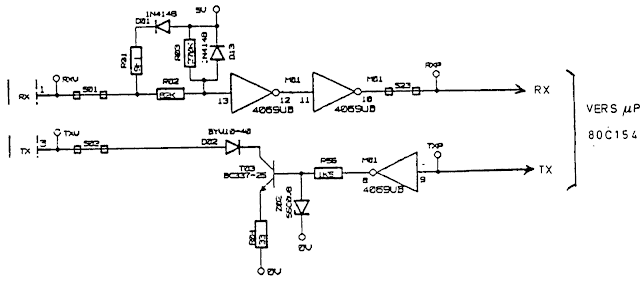
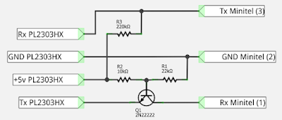
OK, great, but what does the Minitel actually implement since there are no TTL logic gates on the PCB anywhere near the serial port. I ran across a Minitel schematic on line that has the serial port circruit. Here's just the RX and TX part.

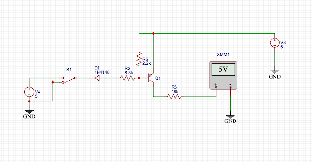
The TX part is the simplest. If the processor is transmitting a 1 then the 4069 hex inverter drives the base of the transistor low which means the transistor is off and the TX port floats. This is why in Pila's USB-to-Minitel connector they pull the TX line to 5V using a resistor:


If the processor wants to send a 0 then the base of the transistor T03 is pulled to 5V and so the transistor conducts (as the base-emitter of the NPN transistor is forward biased). This means the TX line is pulled low (via the transistor) and current flows into the Minitel. Nothing special there.

RX is a whole other kettle of fish. Not a transistor in sight but three resistors and two diodes. The two hex inverters serve to make sure that whatever signal they are presented with they bring it back to clear logic levels. We'll ignore them.

I am using EasyEDA to diagram and simulate.

Receiving 0

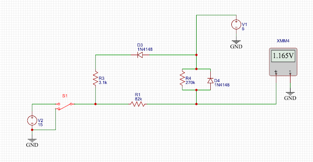
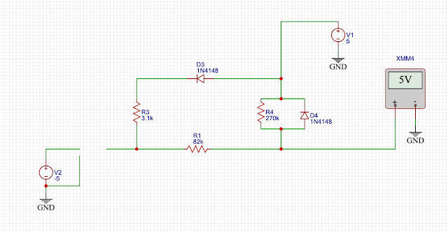
Let's first imagine the scenario where we are transmitting a 0 into the Minitel and pull the RX line low. This looks like:


V1 is the system power (5V), V2 is the voltage source for whatever is connected to the Minitel's serial port. XMM4 measures the voltage presented to the two inverters.

So, with S1 set to pull the RX input to ground the inverters get 1.165V which they will interpret is low. Great. But why 1.165V?

Let's go component by component. D4 is reverse biased and therefore doesn't conduct and does nothing. D3 is forward biased and so current flows through D3/R3 to the RX pin. So, when the Minitel receives data it may source current.

R1 and R2 form a voltage divider which creates precisely 1.165V and also current can flow through them too.

Receiving 1

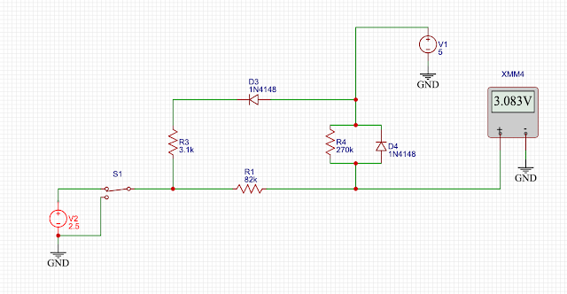
When receiving a 1 the RX line needs to be set between 2.5V and 15V according to the documentation. Let's analyze some different voltages presented on RX. 


We'll start with 2.5V. This is very similar to the 0 case above. D4 does nothing, current flows through D3/R3 out the RX pin and R1/R2 form a voltage divider this time giving a voltage of 3.082V. The inverters see that as high and all is well.


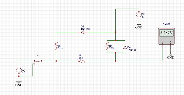
How about 15V? Things are slightly different. D3/R3 does nothing as the diode is reverse biased. D4 is now forward biased and conducts, clamping the voltage presented to 5V + the diode forward voltage (which is about 0.5V). If you check the datasheet of the 4069 inverter it says that its input voltage can be Vdd + 0.5V so that diode keeps voltages in range.

There's no equivalent diode clamping negative voltages, which is a little odd as the 4069 will only accept down to -0.5V. Perhaps it's unnecessary because negative voltages are illegal in France or something.

Finally, what happens if you just let the RX input float and don't connect it at all? This is important for Pila's design. It works fine because R4 pulls up the output to 5V.


Great, so Pila's design makes total sense and works in the real world.

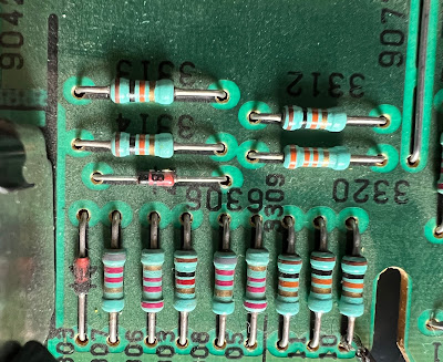
You'd think the story would end there but I couldn't read the value of R01 in the scan of the schematic so figured I'd go look at the actual motherboard and find that resistor. At this point I discovered that my Minitel didn't correspond to the schematic at all. At first I thought I spied the resistors and diodes here:


But that's a 220k resistor not 270k and careful following of the traces (under ultraviolet light for clarity) revealed that the RX circuit is:


A classic PNP switch. Pull it down to turn the transistor on, pull it up or leave it floating otherwise. The TX line is very similar to the schematic. 

So, finally, I have satisfied myself that Pila's design makes sense.

Narrator: he could have just built the thing and not obsessed over it.

Using the USB-to-Minitel cable


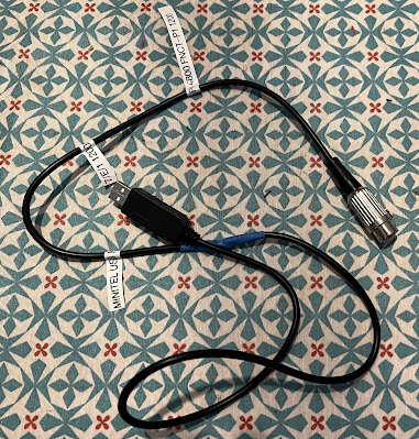
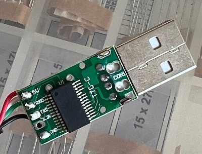
So, I built the thing and here it is:


You could read all about it on Pila's blog but there's a male DIN connector which I've stuffed all the components inside and a USB to serial converter. Pila suggests opening the connector to verify the colours of the connectors so that RX and TX don't get confused. I am very grateful to the person who laid out the tiny PCB inside the USB connector for labelling everything:


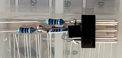
I managed to stuff the transistor and three resistors inside the DIN plug itself as Pila suggests. Tight fit and a bit of heatshrink for insulation.


Once done I tried talking to the Minitel using Python miniterm.py (usually my tool of choice for stuff like this) and saw the following on screen:


If you instantly recognize that the reason a, d, g, h, h, m, n, ... are appearing as blocks is because I've got the wrong number of bits set for the serial transmission then you are a giant nerd. The Minitel is expecting 7 bits plus even parity. Since the top bit for all those characters is 0 for some of the letters the parity will be "correct" but for those characters which have an odd number of 1s in their binary version the parity is wrong and the Minitel displays a white rectangle.

To really use the Minitel as a terminal I plugged it into a Raspberry Pi and it appeared as /dev/ttyUSB0:

stty -F /dev/ttyUSB0 1200 istrip cs7 parenb -parodd brkint  \
ignpar icrnl ixon ixany opost onlcr cread hupcl isig icanon \
echo echoe echok

On the Minitel you can change the baud rate with FNCT-P. Followed by 4 you get 4,800 baud; followed by 1 you get 1,200 baud. 

And it works. To test it I visited jgc.org using lynx:


In the discussion about this post on Hacker News, a reader pointed to their very detailed description of how to use the same cable to turn the Minitel into a really useable terminal with Linux. Worth reading.