Downloaded 247 times
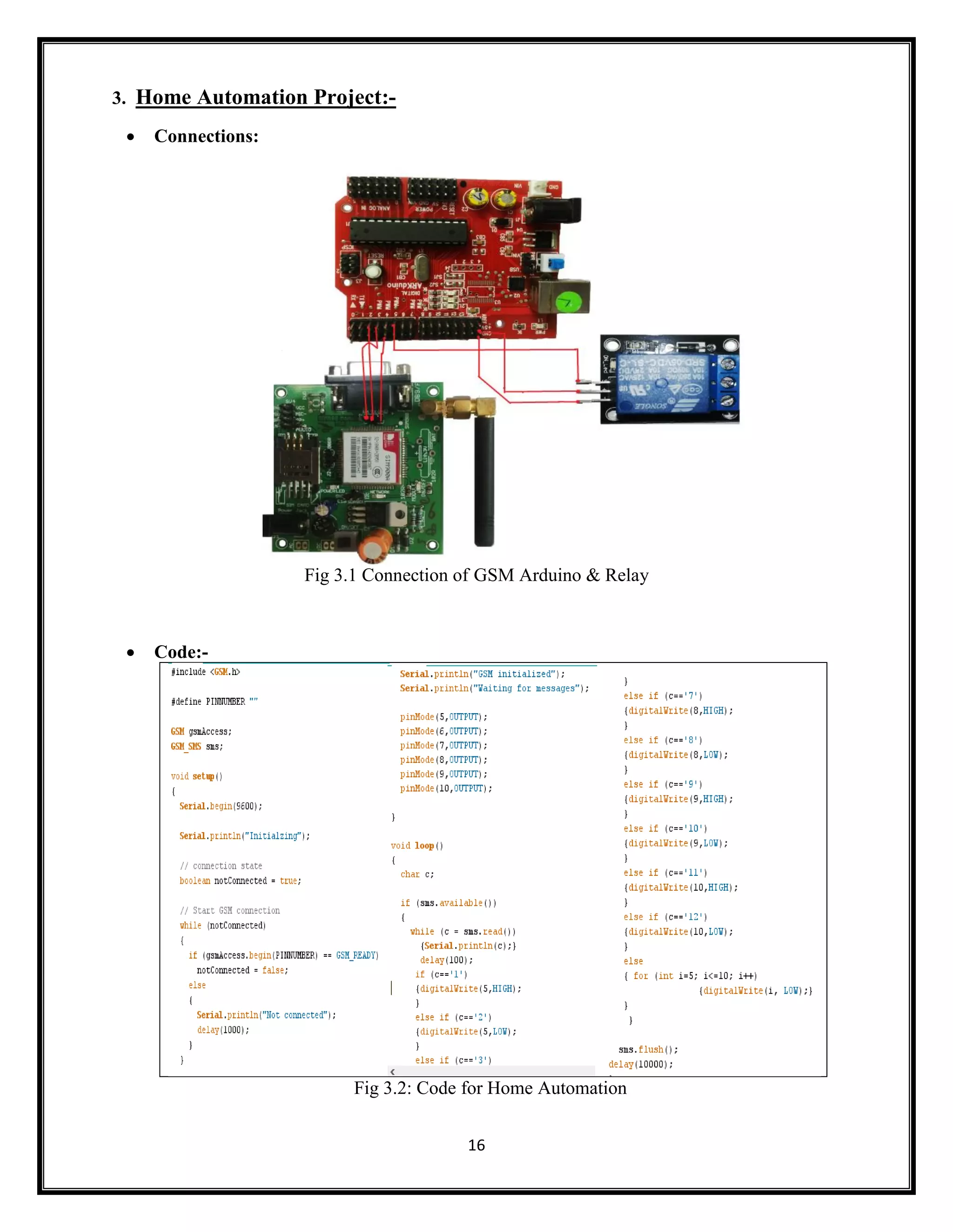

This document summarizes an Arduino seminar report. It discusses what Arduino is, different Arduino boards, how the Arduino board works including the controller, power supply, and USB to serial converter. It also summarizes sensors that can interface with Arduino like temperature sensors and hall sensors. Finally, it provides an overview of a home automation project using Arduino and GSM to control devices remotely through SMS messages.