Downloaded 1,188 times

![Vectors • Net and register data types can be declared as vectors (multiple bit widths) • Syntax: wire/reg [msb_index : lsb_index] data_id; • Example wire a; wire [7:0] bus; wire [31:0] busA, busB, busC; reg clock; reg [0:40] virtual_addr; 14 2005 Verilog HDL](https://image.slidesharecdn.com/verilogtutorial-120525060602-phpapp02/75/Verilog-tutorial-14-2048.jpg)
![Vectors (cont’d) • Consider wire [7:0] bus; wire [31:0] busA, busB, busC; reg [0:40] virtual_addr; • Access to bits or parts of a vector is possible: busA[7] bus[2:0] // three least-significant bits of bus // bus[0:2] is illegal. virtual_addr[0:1] /* two most-significant bits * of virtual_addr */ 15 2005 Verilog HDL](https://image.slidesharecdn.com/verilogtutorial-120525060602-phpapp02/75/Verilog-tutorial-15-2048.jpg)
![Integer, Real, and Time Register Data Types • Integer Keyword: integer Very similar to a vector of reg integer variables are signed numbers reg vectors are unsigned numbers Bit width: implementation-dependent (at least 32-bits) Designer can also specify a width: integer [7:0] tmp; Examples: integer counter; initial counter = -1; 16 2005 Verilog HDL](https://image.slidesharecdn.com/verilogtutorial-120525060602-phpapp02/75/Verilog-tutorial-16-2048.jpg)
![Arrays • Only one-dimensional arrays supported • Allowed for reg, integer, time Not allowed for real data type • Syntax: <data_type> <var_name>[start_idx : end_idx]; • Examples: integer count[0:7]; reg bool[31:0]; time chk_point[1:100]; reg [4:0] port_id[0:7]; integer matrix[4:0][4:0]; // illegal count[5] chk_point[100] port_id[3] • Note the difference between vectors and arrays 19 2005 Verilog HDL](https://image.slidesharecdn.com/verilogtutorial-120525060602-phpapp02/75/Verilog-tutorial-19-2048.jpg)
![Memories • RAM, ROM, and register-files used many times in digital systems • Memory = array of registers in Verilog • Word = an element of the array Can be one or more bits • Examples: reg membit[0:1023]; reg [7:0] membyte[0:1023]; membyte[511] • Note the difference (as in arrays): reg membit[0:127]; reg [0:127] register; 20 2005 Verilog HDL](https://image.slidesharecdn.com/verilogtutorial-120525060602-phpapp02/75/Verilog-tutorial-20-2048.jpg)
![Data Types ~ summary module sample (a,b,c,d); • Data Values: 0,1,x,z input a,b; • Wire output c,d; - Synthesizes into wires - Used in structural code wire [7:0] b; • Reg - May synthesize into latches, flip-flops or wires reg c,d; - Used in procedural code integer k; • Integer 32-bit integer used as indexes • Input, Output, inout Defines ports of a module (wire by default) 21](https://image.slidesharecdn.com/verilogtutorial-120525060602-phpapp02/75/Verilog-tutorial-21-2048.jpg)

![Data Values • Numbers: Numbers are defined by number of • Parameters: bits Value of 23: parameter n=4; 5’b10111 // Binary wire [n-1:0] t, d; 5’d23 // Decimal 5’h17 // Hex `define Reset_state = 0, state_B =1, • Constants: Run_state =2, finish_state = 3; wire [3:0] t,d; if(state==`Run_state) assign t = 23; assign d= 4’b0111; 23](https://image.slidesharecdn.com/verilogtutorial-120525060602-phpapp02/75/Verilog-tutorial-23-2048.jpg)
![numbers.v module numbers; integer i, j; Register array. reg[3:0] x, y; initial ‘<base>: base can be d, b, o, h Array of register arrays simulate begin memory. Example memory i = ‘b1101; declaration with 1K 32-bit words: $display( "decimal i = %d, binary i = %b", i, i ); reg[31:0] smallMem[0:1023]; $display( "octal i = %o, hex i = %h", i, i ); Default base: d j = -1; $display( "decimal j = %d, binary j = %b", j, j ); Negative numbers are stored $display( "octal j = %o, hex j = %h", j, j ); in two’s complement form. x = 4'b1011; $display( "decimal x = %d, binary x = %b", x, x ); $display( "octal x = %o, hex x = %h", x, x ); y = 4'd7; $display( "decimal y = %d, binary y = %b", y, y ); $display( "octal y = %o, hex y = %h", y, y ); Typical format: <size>’<base><number> $finish; size is a decimal value that specifies the end endmodule size of the number in bits.](https://image.slidesharecdn.com/verilogtutorial-120525060602-phpapp02/75/Verilog-tutorial-24-2048.jpg)
![Operators • Arithmetic: reg [3:0] a, b, c, d; *,+,-, /,% wire[7:0] x,y,z; • Relational parameter n =4; <,<=,>,>=,==, != • Bit-wise Operators c = a + b; • Not: ~ d = a *n; • XOR: ^ • And : & 5’b11001 & 5’b01101 ==> 5’b01001 If(x==y) d = 1; else d =0; • OR: | • XNOR: ~^ or ^~ d = a ~^ b; • Logical Operators Returns 1or 0, treats all nonzero as 1 if ((x>=y) && (z)) a=1; • ! : Not else a = !x; • && : AND 27 && -3 ==> 1 • || : OR 25](https://image.slidesharecdn.com/verilogtutorial-120525060602-phpapp02/75/Verilog-tutorial-25-2048.jpg)
![Operators module sample (a, b, c, d); • Reduction Operators: input [2:0] a, b; Unary operations returns single-bit values output [2;0] c, d; • & : and wire z,y; • | :or • ~& : nand assign z = ~| a; • ~| : nor c = a * b; • ^ : xor If(a==b) d = 1; else d =0; • ~^ :xnor • Shift Operators d = a ~^ b; Shift Left: << Shift right: >> if ((a>=b) && (z)) y=1; • Concatenation Operator else y = !x; { } (concatenation) { n{item} } (n fold replication of an item) assign d << 2; //shift left twice • Conditional Operator assign {carry, d} = a + b; assign c = {2{carry},2{1’b0}}; Implements if-then-else statement // c = {carry,carry,0,0} (cond) ? (result if cond true) : (result if cond false) assign c= (inc==2)? a+1:a-1; 26](https://image.slidesharecdn.com/verilogtutorial-120525060602-phpapp02/75/Verilog-tutorial-26-2048.jpg)
![Structural Vs Procedural Procedural Structural reg [3:0] Q; wire [3:0]Q; wire [1:0] y; wire [1:0]y; always@(y) begin assign Q=4’b0000; Q[0]=(~y[1])&(~y[0]), case(y) begin Q[1]=(~y[1])&y[0], 2’b00: Q[0]=1; Q[2]=y[1]&(~y[0]), 2’b01: Q[1]=1; Q[3]=y[1]&y[0]; 2’b10: Q[2]=1; 2’b11: Q[3]=1; endcase Q[0] end Q[1] y[0] You don’t Q[0] Q[2] have to Q[1] y[1] work out Q[2] y[0] logic Q[3] Q[3] y[1] 30](https://image.slidesharecdn.com/verilogtutorial-120525060602-phpapp02/75/Verilog-tutorial-30-2048.jpg)
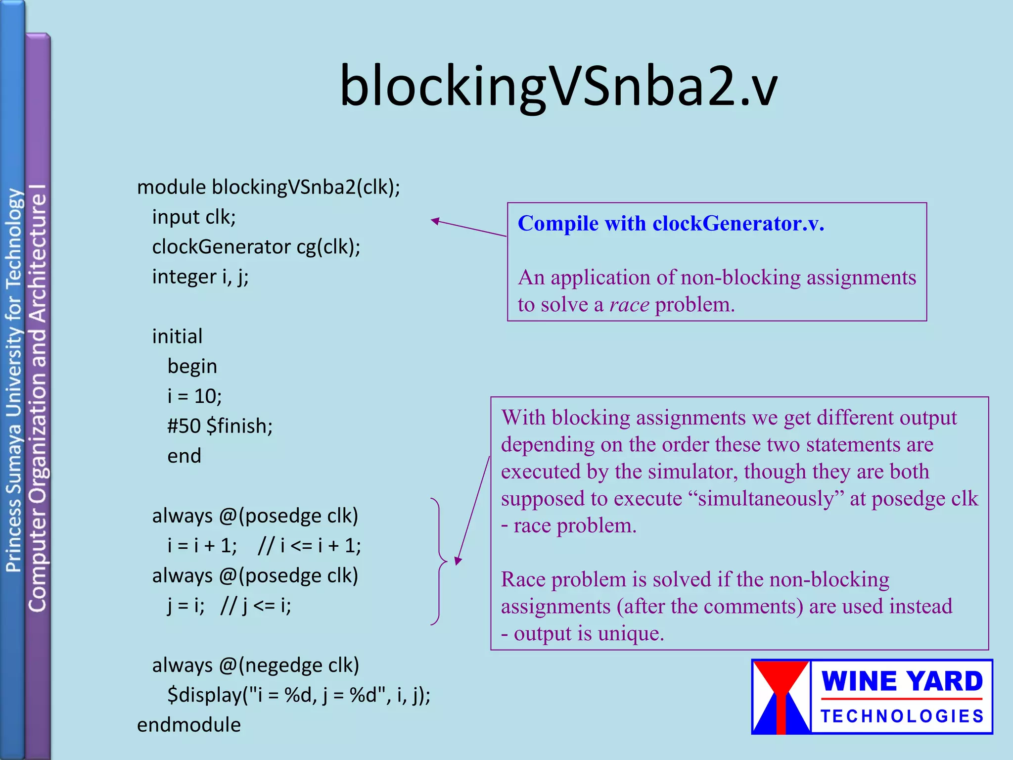
![blockingVSnba3.v The most important application of module blockingVSnba3; non-blocking assignments is to reg[7:0] dataBuf, dataCache, instrBuf, instrCache; model concurrency in hardware systems at the behavioral level. initial begin dataCache = 8'b11010011; Both loads from dataCache to dataBuf and instrCache = 8'b10010010; instrCache to instrBuf happen concurrently in the 20-21 clock cycle. #20; $display("Time = %d, dataBuf = %b, instrBuf = %b", $time, dataBuf, instrBuf); dataBuf <= #1 dataCache; instrBuf <= #1 instrCache; #1 $display("Time = %d, dataBuf = %b, instrBuf = %b", $time, dataBuf, instrBuf); $finish; Replace non-blocking with blocking end assignments and observe. endmodule](https://image.slidesharecdn.com/verilogtutorial-120525060602-phpapp02/75/Verilog-tutorial-35-2048.jpg)
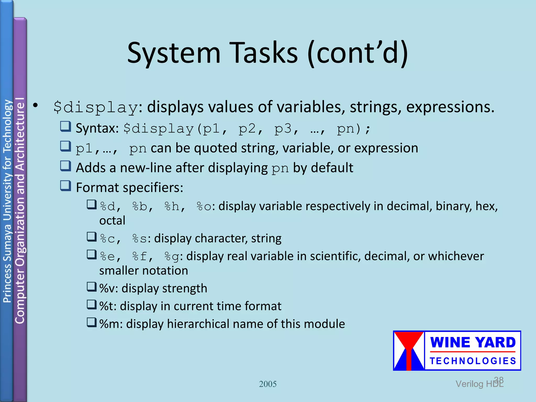
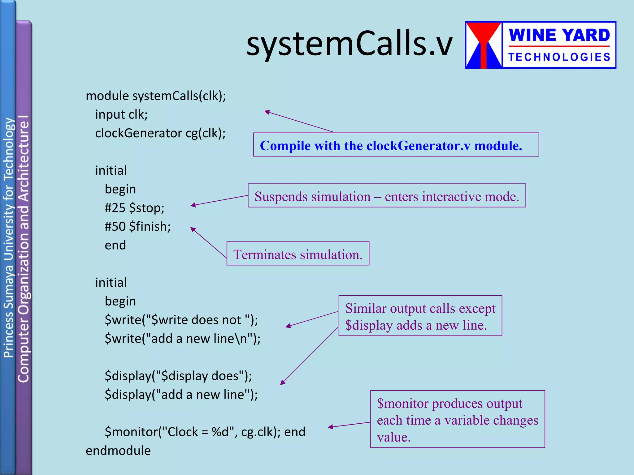
![System Tasks (cont’d) • $display examples: $display(“Hello Verilog World!”); Output: Hello Verilog World! $display($time); Output: 230 reg [0:40] virtual_addr; $display(“At time %d virtual address is %h”, $time, virtual_addr); Output: At time 200 virtual address is 1fe000001c 2005 39 Verilog HDL](https://image.slidesharecdn.com/verilogtutorial-120525060602-phpapp02/75/Verilog-tutorial-39-2048.jpg)
![System Tasks (cont’d) • reg [4:0] port_id; • $display(“ID of the port is %b”, port_id); Output: ID of the port is 00101 • reg [3:0] bus; • $display(“Bus value is %b”, bus); Output: Bus value is 10xx • $display(“Hierarchical name of this module is %m”); Output: Hierarchical name of this module is top.p1 • $display(“A n multiline string with a %% sign.”); Output: A multiline string with a % sign. 2005 40 Verilog HDL](https://image.slidesharecdn.com/verilogtutorial-120525060602-phpapp02/75/Verilog-tutorial-40-2048.jpg)
![Compiler Directives • General syntax: `<keyword> • `define: similar to #define in C, used to define macros • `<macro_name> to use the macro defined by `define • Examples: `define WORD_SIZE 32 `define S $stop `define WORD_REG reg [31:0] `WORD_REG a_32_bit_reg; 2005 44 Verilog HDL](https://image.slidesharecdn.com/verilogtutorial-120525060602-phpapp02/75/Verilog-tutorial-44-2048.jpg)
![For loops Syntax for (count= value1; integer j; count</<=/>/>= value2; count=count+/- step) for(j=0;j<=7;j=j+1) begin begin ...statements... c[j] = a[j] + b[j]; end end 52](https://image.slidesharecdn.com/verilogtutorial-120525060602-phpapp02/75/Verilog-tutorial-52-2048.jpg)
![Shift Registers reg[3:0] Q; always@(posedge clk or posedge rset ) begin if (rset) Q<=0; else begin D Q D Q D Q D Q Q <=Q << 1; Q[0]<=Q[3]; CLK CLK CLK CLK end clk 57](https://image.slidesharecdn.com/verilogtutorial-120525060602-phpapp02/75/Verilog-tutorial-57-2048.jpg)
![Counters reg [7:0] count; wire enable; rst always@(posedge clk or negedge rst) clr enable EN begin if (rst) count<=0; else if (enable) count count<=count+1; end 59](https://image.slidesharecdn.com/verilogtutorial-120525060602-phpapp02/75/Verilog-tutorial-59-2048.jpg)
![4-bit Adder • Step 2: initiate 4 instances of FA_1bit module B3 A3 A B A B2 A2 B1 1 0 0 1-bit Cout2 1-bit Cout1 1-bit Cout0 1-bit Full Full Full Full Cout Adder Adder Adder Adder Cin S3 S2 S1 S0 module FA_4bits (S,Cout,A,B,Cin); The inputs and the output are begin input [3:0] A, B; 4-bits wide input Cin; we need wires to propagate output [3:0] S; output Cout the carry from one stage to wire Cout0, Cout1, Cout2 the next FA_1bit FA1(S[0], Cout0,A[0],B[0],Cin); you may name the instances FA_1bit FA1(S[1], Cout1,A[1],B[1],Cout0); with any name, but you have FA_1bit FA1(S[2], Cout2,A[2],B[2],Cout1); to maintain the order of the FA_1bit FA1(S[3], Cout,A[3],B[3],Cout2); inputs and outputs end endmodule; 62](https://image.slidesharecdn.com/verilogtutorial-120525060602-phpapp02/75/Verilog-tutorial-62-2048.jpg)
![4-bit Adder • Step 3: write a test-bench to test your design and generate outs using sample inputs. test_bench initialize the inputs, and read the outputs Write a test_bench to A[3:0] 4 B[3:0] 4 4-bits Full Adder 4 S[3:0] test the design. Cin Cout](https://image.slidesharecdn.com/verilogtutorial-120525060602-phpapp02/75/Verilog-tutorial-63-2048.jpg)
![4-bit Adder module test_bench; // you may name it by any name //define the variables you will use in the design reg [3:0] A,B,S; reg Cin, Cout // Create an instance from the full adder FA_4bits FA(S[3:0],Cout, A[3:0], B[3:0], Cin); //initialize the variables once initial A = 5; B = 6; S = 0; Cin = 0; Cout = 0; initial begin $display(“A=%d, B=%d, the sum = %d, and the carry = %d”, A,B,S,Cout) $display $finish end endmodule](https://image.slidesharecdn.com/verilogtutorial-120525060602-phpapp02/75/Verilog-tutorial-64-2048.jpg)
![4-bit Adder module test_bench; // you may name it by any name //define the variables you will use in the design reg [3:0] A,B,S; integer I,j; reg Cin, Cout // Create an instance from the full adder FA_4bits FA(S,Cout, A, B, Cin); //initialize the variables once initial begin $monitor ("A: %d B: %d sum: %d carry: %d", A, B, sum, carry); for (i=0; i<16; i=i+1) for (j=0; j<16; j=j+1) begin A = i; B = j; #1 ; end System calls. $finish; $finish end endmodule](https://image.slidesharecdn.com/verilogtutorial-120525060602-phpapp02/75/Verilog-tutorial-65-2048.jpg)
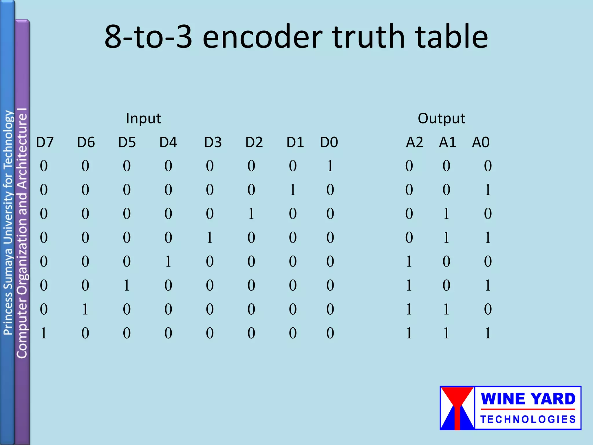
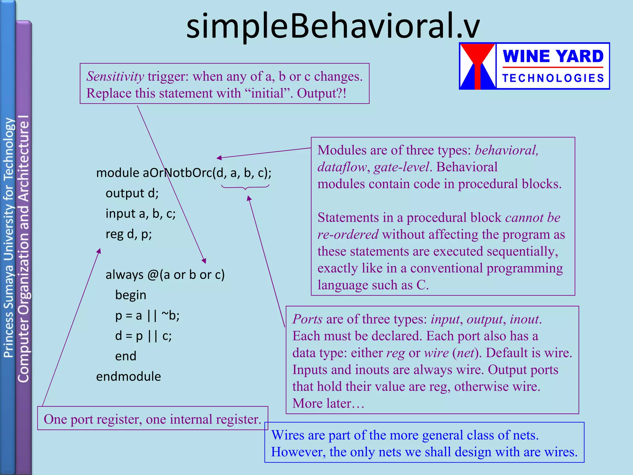
![encoder8_3Behavioral.v module encoder8_3( encoder_out , enable, encoder_in ); output[2:0] encoder_out; input enable; Sensitivity list. input[7:0] encoder_in; reg[2:0] encoder_out; always @ (enable or encoder_in) Simple behavioral code using the begin case statement. if (enable) case ( encoder_in ) 8'b00000001 : encoder_out = 3'b000; 8'b00000010 : encoder_out = 3'b001; 8'b00000100 : encoder_out = 3'b010; 8'b00001000 : encoder_out = 3'b011; 8'b00010000 : encoder_out = 3'b100; 8'b00100000 : encoder_out = 3'b101; 8'b01000000 : encoder_out = 3'b110; 8'b10000000 : encoder_out = 3'b111; default : $display("Check input bits."); endcase end endmodule](https://image.slidesharecdn.com/verilogtutorial-120525060602-phpapp02/75/Verilog-tutorial-87-2048.jpg)
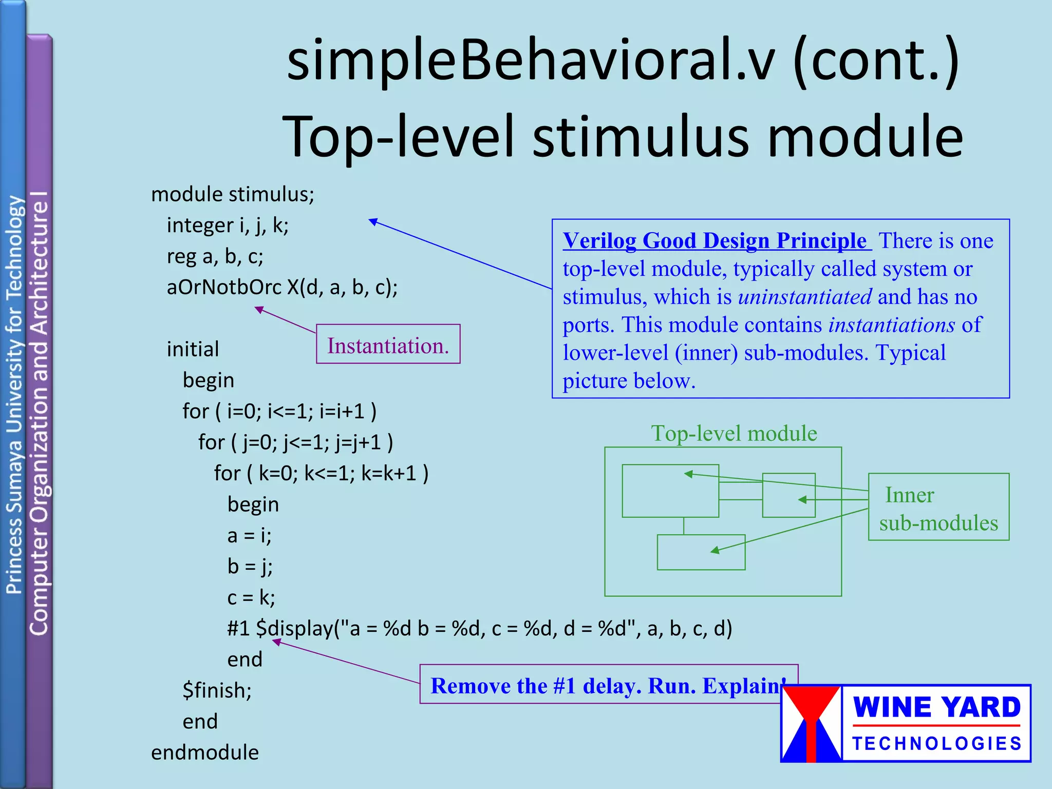
![encoder8_3BehavioralStimulus.v module stimulus; wire[2:0] encoder_out; reg enable; Stimulus for the behavioral code. reg[7:0] encoder_in; encoder8_3 enc( encoder_out, enable, encoder_in ); initial begin enable = 1; encoder_in = 8'b00000010; #1 $display("enable = %b, encoder_in = %b, encoder_out = %b", enable, encoder_in, encoder_out); Remove this delay. #1 enable = 0; encoder_in = 8'b00000001; Run. Explain! #1 $display("enable = %b, encoder_in = %b, encoder_out = %b", enable, encoder_in, encoder_out); #1 enable = 1; encoder_in = 8'b00000001; #1 $display("enable = %b, encoder_in = %b, encoder_out = %b", enable, encoder_in, encoder_out); #1 $finish; end endmodule](https://image.slidesharecdn.com/verilogtutorial-120525060602-phpapp02/75/Verilog-tutorial-88-2048.jpg)
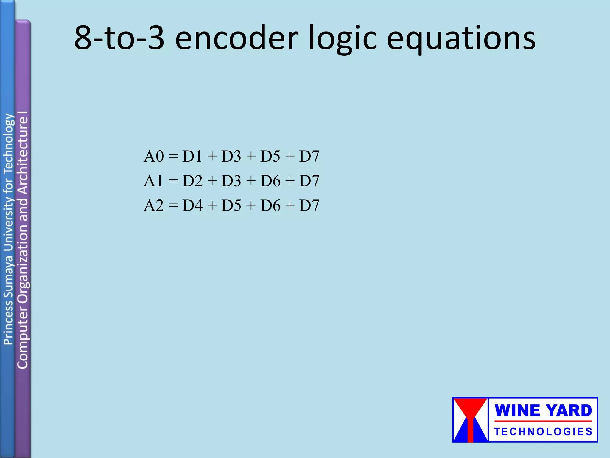
![encoder8_3structural.v (Folder Encoder) module encoder8_3( encoder_out , encoder_in ); output[2:0] encoder_out; Structural code. Why is there no input[7:0] encoder_in; enable wire?! Hint: think storage. or( encoder_out[0], encoder_in[1], encoder_in[3], encoder_in[5], encoder_in[7] ); or( encoder_out[1], encoder_in[2], encoder_in[3], encoder_in[6], encoder_in[7] ); or( encoder_out[2], encoder_in[4], encoder_in[5], encoder_in[6], encoder_in[7] ); endmodule](https://image.slidesharecdn.com/verilogtutorial-120525060602-phpapp02/75/Verilog-tutorial-90-2048.jpg)
![encoder8_3StructuralStimulus.v module stimulus; wire[2:0] encoder_out; Stimulus for the structural code. reg[7:0] encoder_in; encoder8_3 enc( encoder_out, encoder_in ); initial begin encoder_in = 8'b00000010; #1 $display("encoder_in = %b, encoder_out = %b", encoder_in, encoder_out); #1 encoder_in = 8'b00000001; #1 $display("encoder_in = %b, encoder_out = %b", encoder_in, encoder_out); #1 $finish; end endmodule](https://image.slidesharecdn.com/verilogtutorial-120525060602-phpapp02/75/Verilog-tutorial-91-2048.jpg)
![encoder8_3Mixed.v module encoder8_3( encoder_out , enable, encoder_in ); output[2:0] encoder_out; input enable; Mixed structural-behavioral code. Goal was input[7:0] encoder_in; to modify structural code to have an enable reg[2:0] encoder_out; wire, which requires register output for storage. wire b0, b1, b2; or( b0, encoder_in[1], encoder_in[3], encoder_in[5], encoder_in[7] ); or( b1, encoder_in[2], encoder_in[3], encoder_in[6], encoder_in[7] ); or( b2, encoder_in[4], encoder_in[5], encoder_in[6], encoder_in[7] ); always @(enable or encoder_in) Be careful with mixed design! It’s begin working may be difficult to understand. if (enable) encoder_out = {b2, b1, b0}; end endmodule](https://image.slidesharecdn.com/verilogtutorial-120525060602-phpapp02/75/Verilog-tutorial-92-2048.jpg)
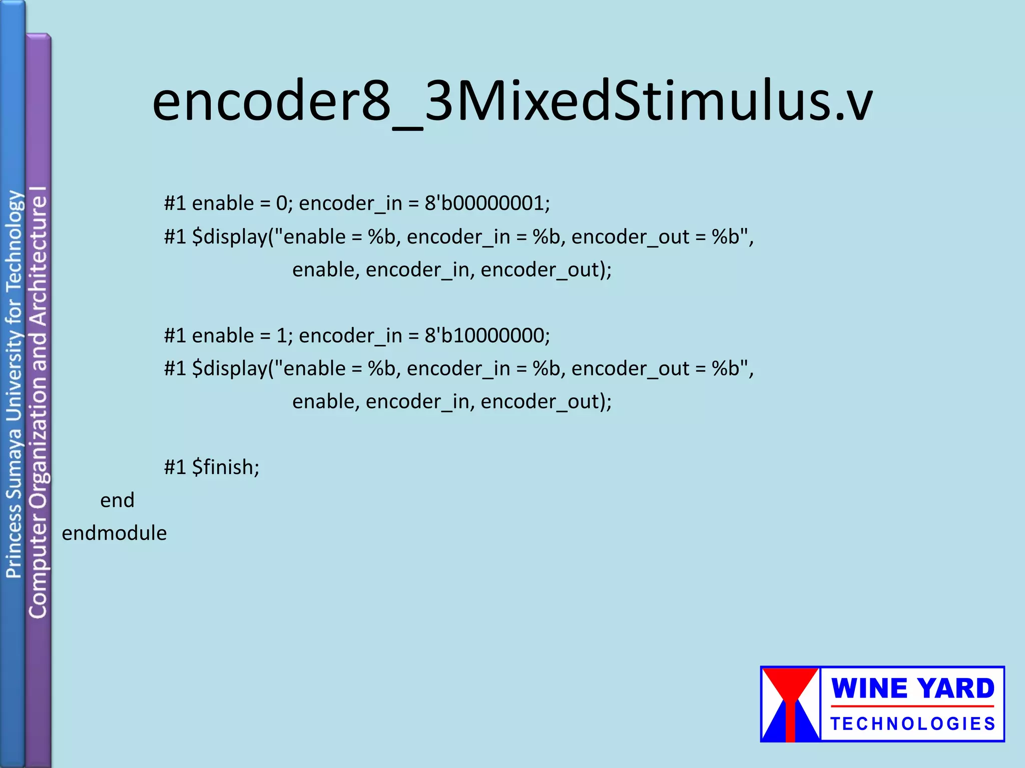
![encoder8_3MixedStimulus.v module stimulus; wire[2:0] encoder_out; reg enable; Stimulus for the mixed code. reg[7:0] encoder_in; encoder8_3 enc( encoder_out, enable, encoder_in ); initial begin Output is puzzling! Explain! enable = 1; encoder_in = 8'b00000010; #1 $display("enable = %b, encoder_in = %b, encoder_out = %b", enable, encoder_in, encoder_out); #1 enable = 1; encoder_in = 8'b00000010; #1 $display("enable = %b, encoder_in = %b, encoder_out = %b", enable, encoder_in, encoder_out);](https://image.slidesharecdn.com/verilogtutorial-120525060602-phpapp02/75/Verilog-tutorial-93-2048.jpg)
![comparator.v Parameters that may be set Comparator makes the comparison A ? B when the module is instantiated. where ? Is determined by the input greaterNotLess and returns true(1) or false(0). module comparator (result, A, B, greaterNotLess); parameter width = 8; parameter delay = 1; input [width-1:0] A, B; // comparands input greaterNotLess; // 1 - greater, 0 - less than output result; // 1 if true, 0 if false assign #delay result = greaterNotLess ? (A > B) : (A < B); endmodule](https://image.slidesharecdn.com/verilogtutorial-120525060602-phpapp02/75/Verilog-tutorial-96-2048.jpg)
![stimulus.v Stimulus for the comparator. module system; wire greaterNotLess; // sense of comparison wire [15:0] A, B; // comparand values - 16 bit wire result; // comparison result // Module instances comparator #(16, 2) comp (result, A, B, greaterNotLess); testGenerator tg (A, B, greaterNotLess, result); endmodule Parameters being set at module instantiation.](https://image.slidesharecdn.com/verilogtutorial-120525060602-phpapp02/75/Verilog-tutorial-97-2048.jpg)
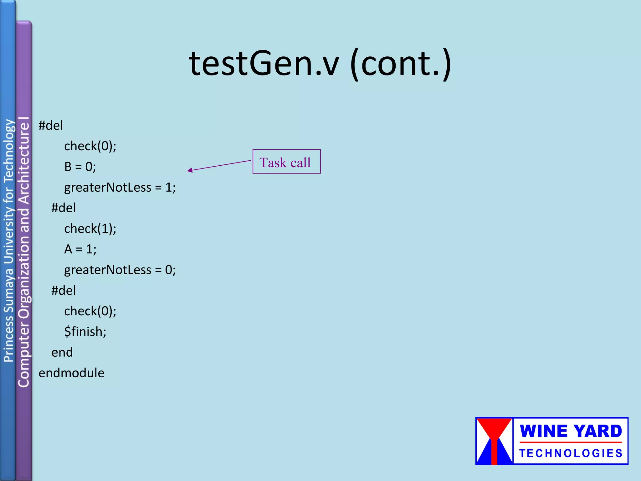
![testGen.v module testGenerator (A, B, greaterNotLess, result); output [15:0] A, B; output greaterNotLess; Module that generates test vectors for input result; the comparator and checks correctness parameter del = 5; of output. reg [15:0] A, B; reg greaterNotLess; task check; input shouldBe; Task definition: a task is exactly like a procedure in a conventional programming language. begin if (result != shouldBe) $display("Error! %d %s %d, result = %b", A, greaterNotLess?">":"<", B, result); end endtask initial begin // produce test data, check results A = 16'h1234; B = 16'b0001001000110100; greaterNotLess = 0;](https://image.slidesharecdn.com/verilogtutorial-120525060602-phpapp02/75/Verilog-tutorial-98-2048.jpg)
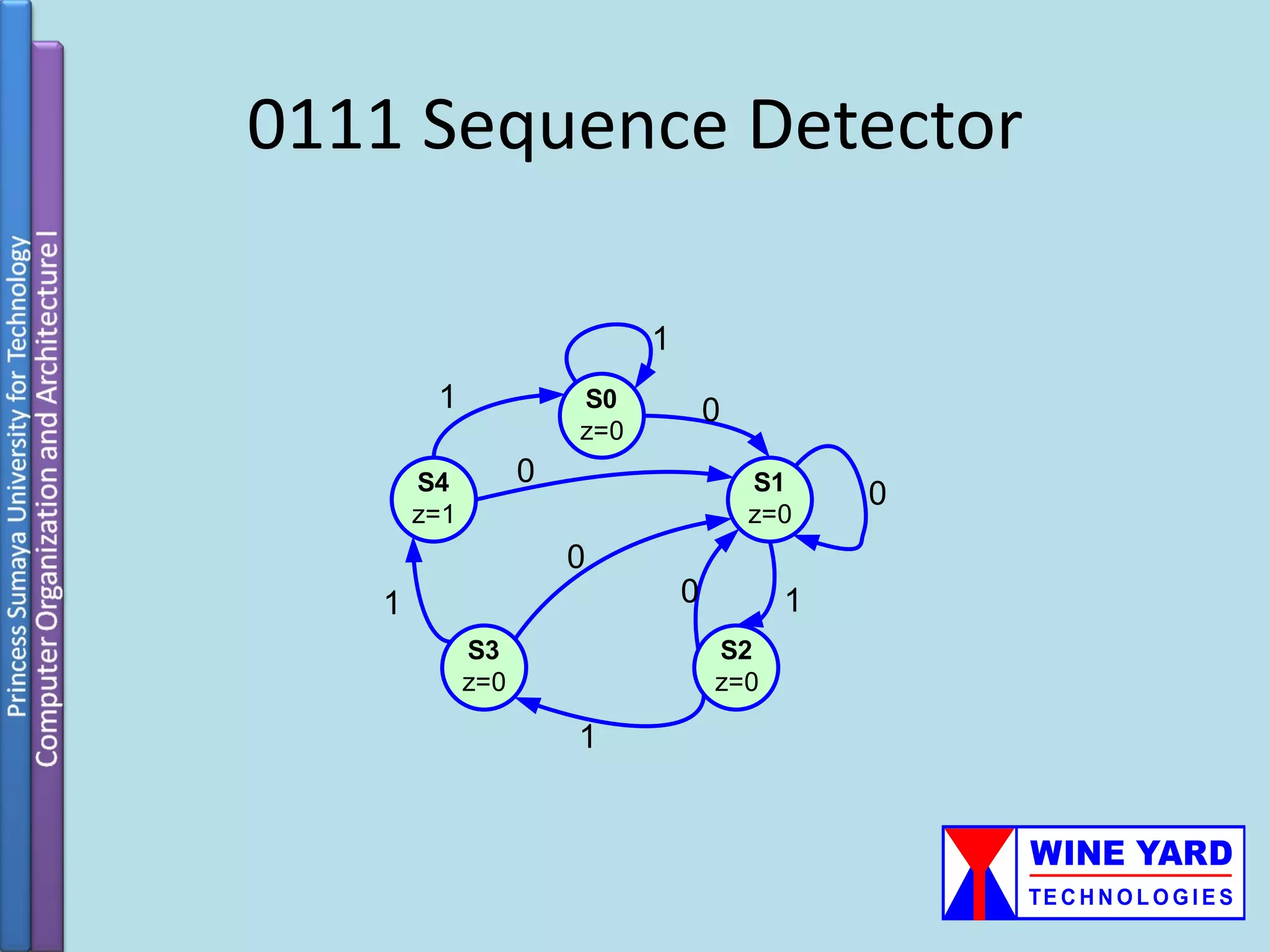
![Standard Form for a Verilog FSM // state flip-flops // REGISTER DEFINITION reg [2:0] state, nxt_st; always@(posedge clk) // state definitions begin parameter reset=0,S1=1,S2=2,S3=3,.. state<=next_state; end // NEXT STATE CALCULATIONS always@(state or inputs or ...) // OUTPUT CALCULATIONS begin output= f(state, inputs) … next_state= ... … end 101](https://image.slidesharecdn.com/verilogtutorial-120525060602-phpapp02/75/Verilog-tutorial-101-2048.jpg)
![Example module myFSM (clk, x, z) // NEXT STATE CALCULATIONS input clk, x; always @(state or x) output z; begin // state flip-flops case (state) reg [2:0] state, nxt_st; S0: if(x) nxt_st=S1; // state definition else nxt_st=S0; S1: if(x) nxt_st=S3; parameter S0=0,S1=1,S2=2,S3=3,S7=7 else nxt_st=S2; S2: if(x) nxt_st=S0; else nxt_st=S7; // REGISTER DEFINITION S3: if(x) nxt_st=S2; always @(posedge clk) else nxt_st=S7; begin S7: nxt_st=S0; state<=nxt_st; default: nxt_st = S0; end endcase end // OUTPUTCALCULATIONS assign z = (state==S7); endmodule 102](https://image.slidesharecdn.com/verilogtutorial-120525060602-phpapp02/75/Verilog-tutorial-102-2048.jpg)

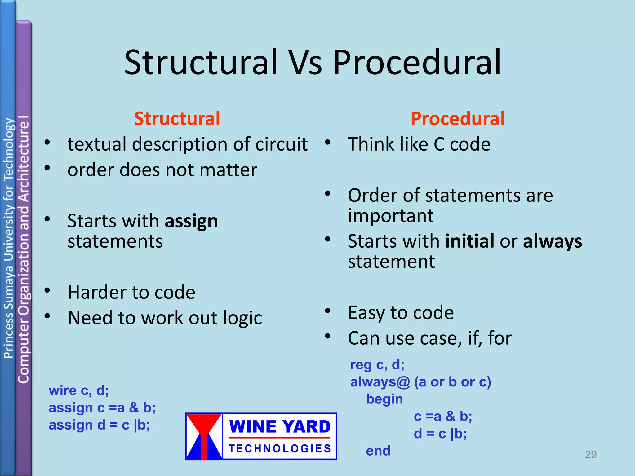
This document provides an introduction to Verilog, a hardware description language (HDL). It describes the main purposes of HDLs as allowing designers to describe circuits at both the algorithmic and gate levels, enabling simulation and synthesis. The document then discusses some Verilog basics, including modules as building blocks, ports, parameters, variables, instantiation, and structural vs procedural code. It provides examples of module declarations and typical module components.
Overview of Verilog as a Hardware Description Language (HDL) used for circuit description and simulation.
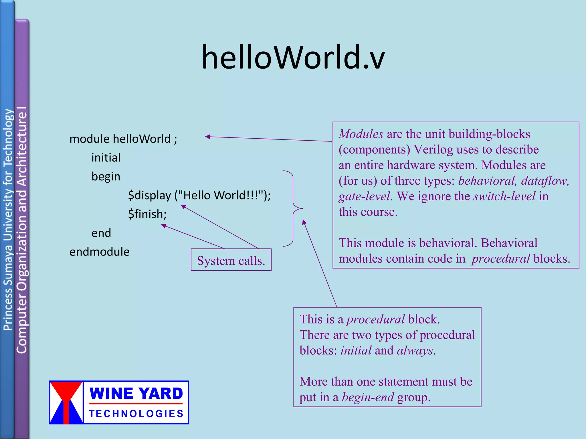
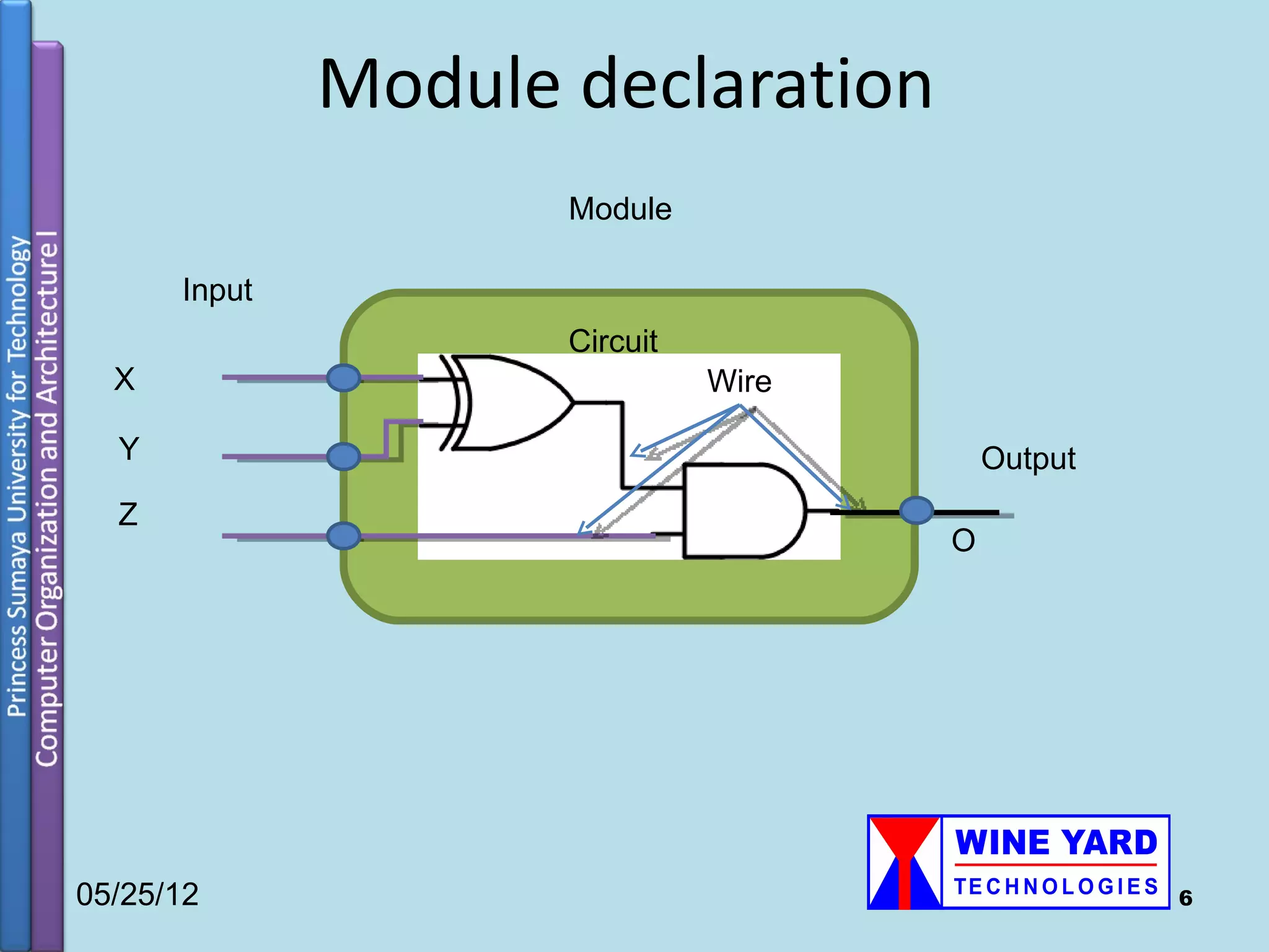
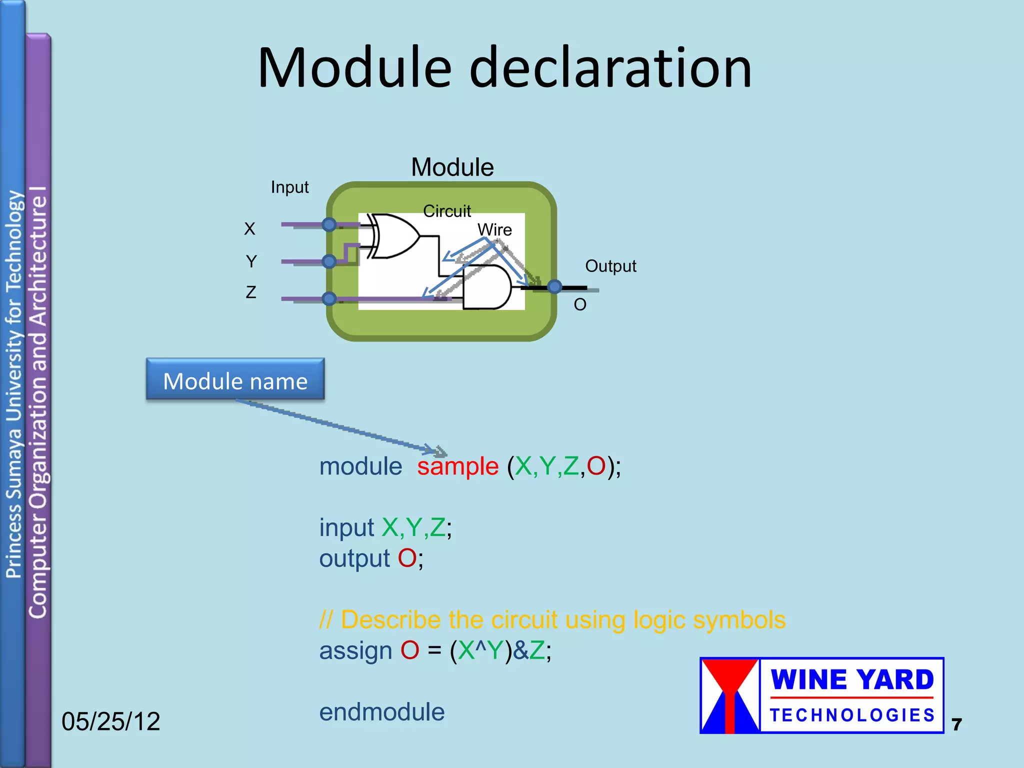
Introduction to module creation in Verilog, including module declaration and components of a typical module.
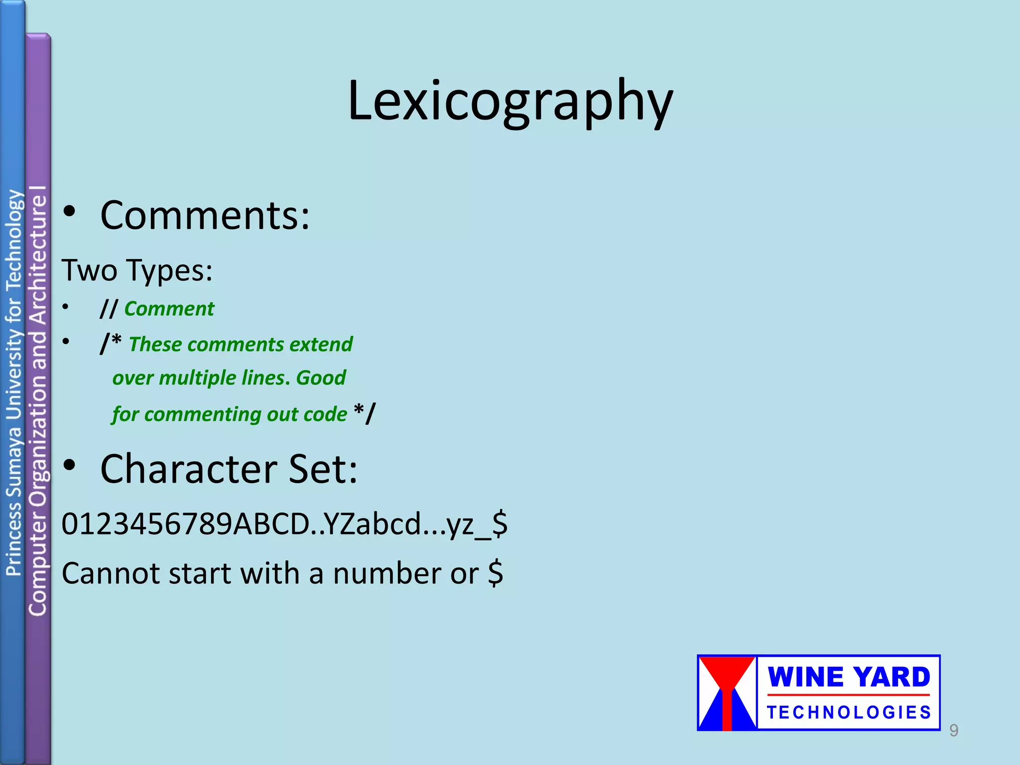
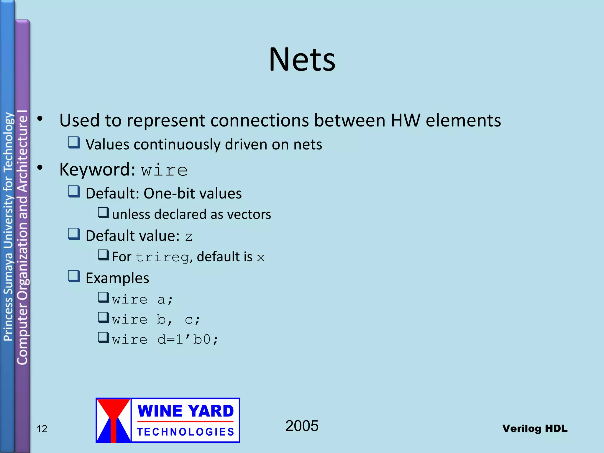
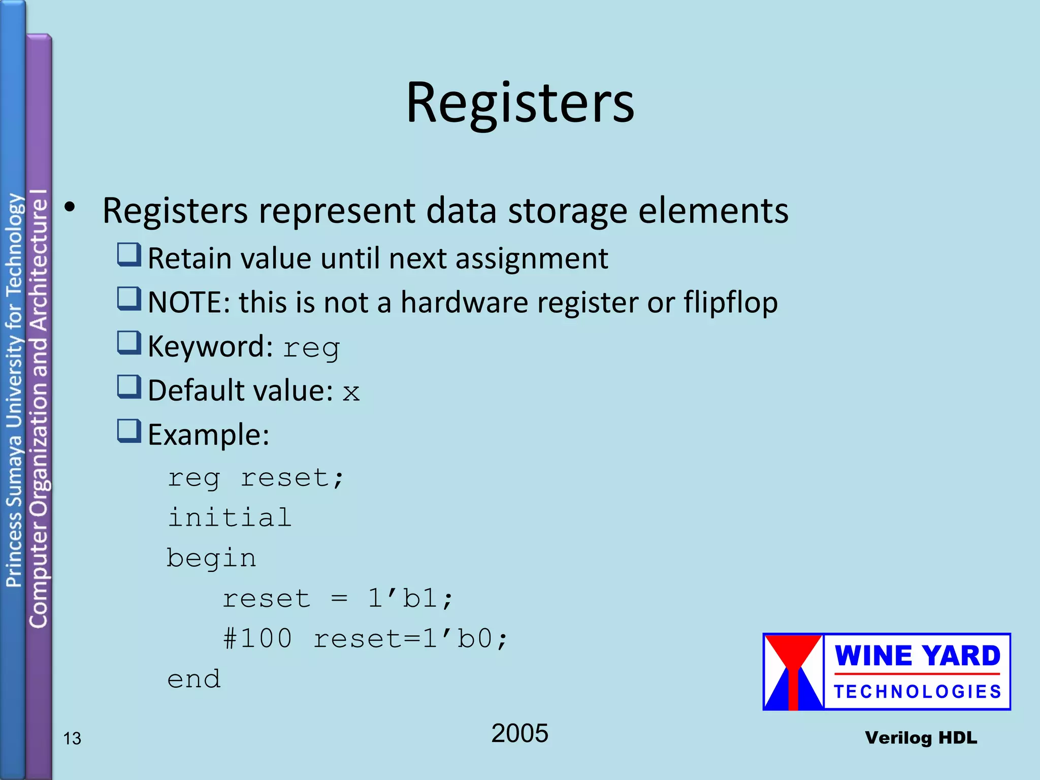
Various data types including nets, registers, vectors, and their usage for representing hardware elements.
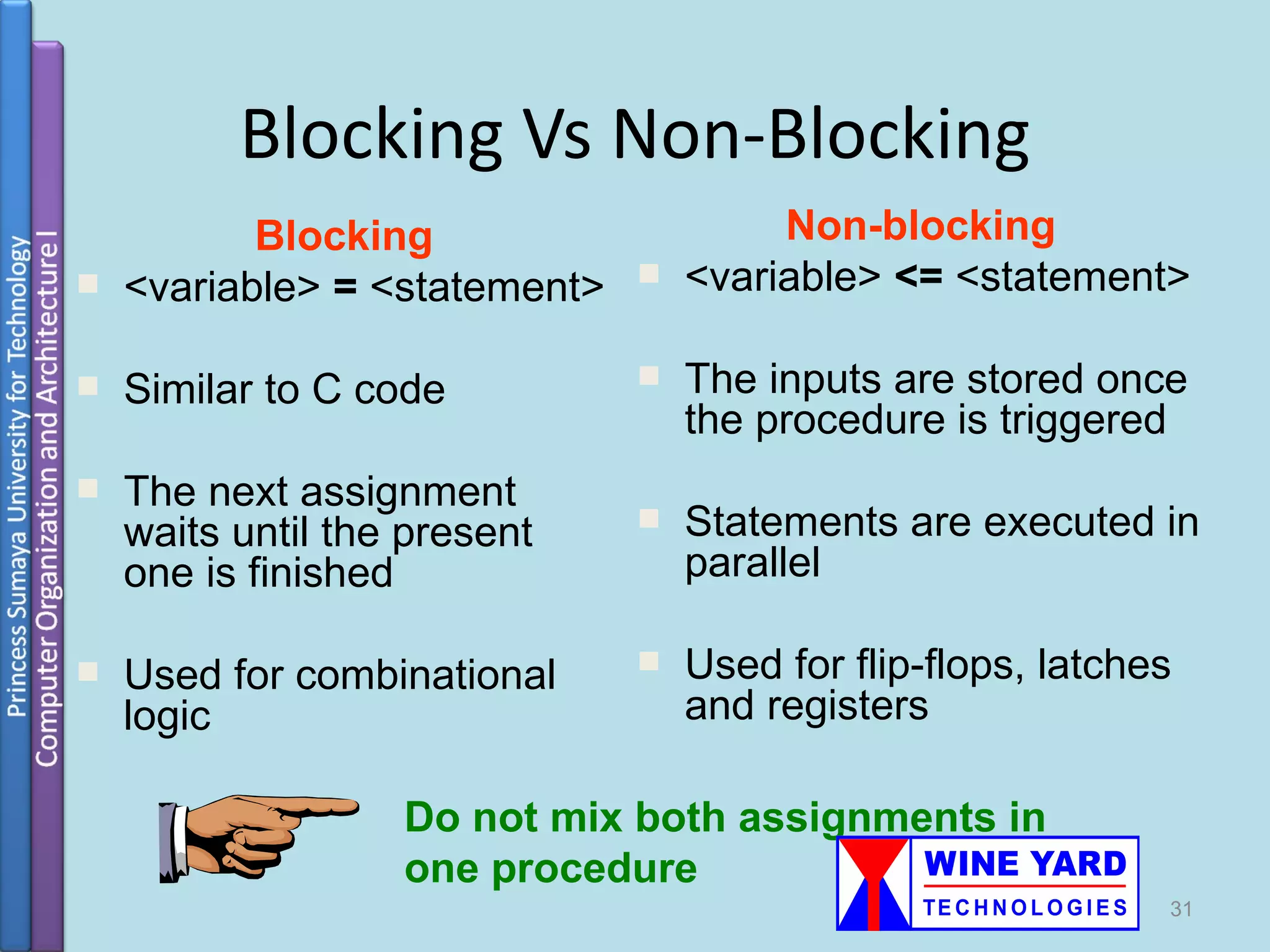
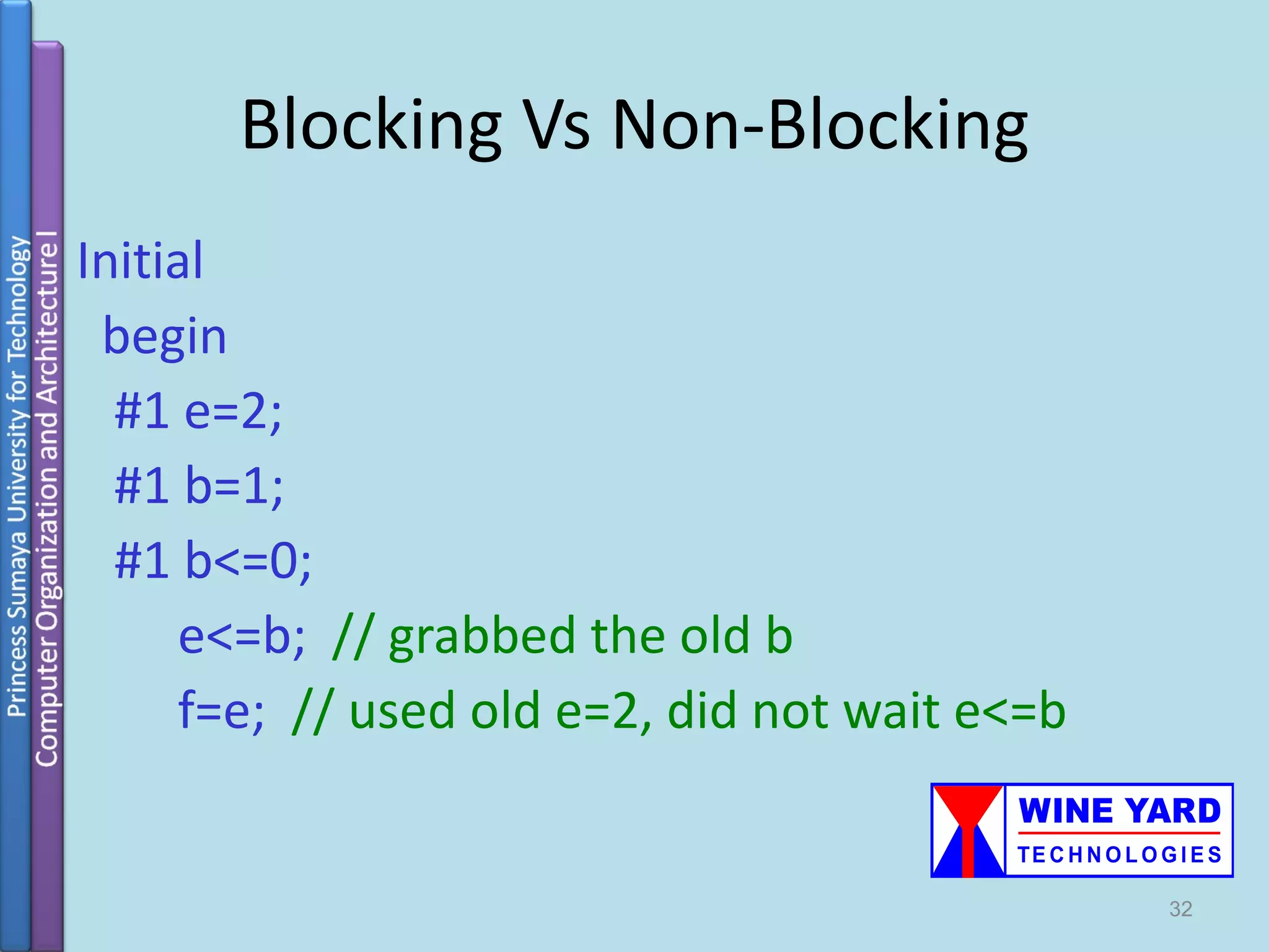
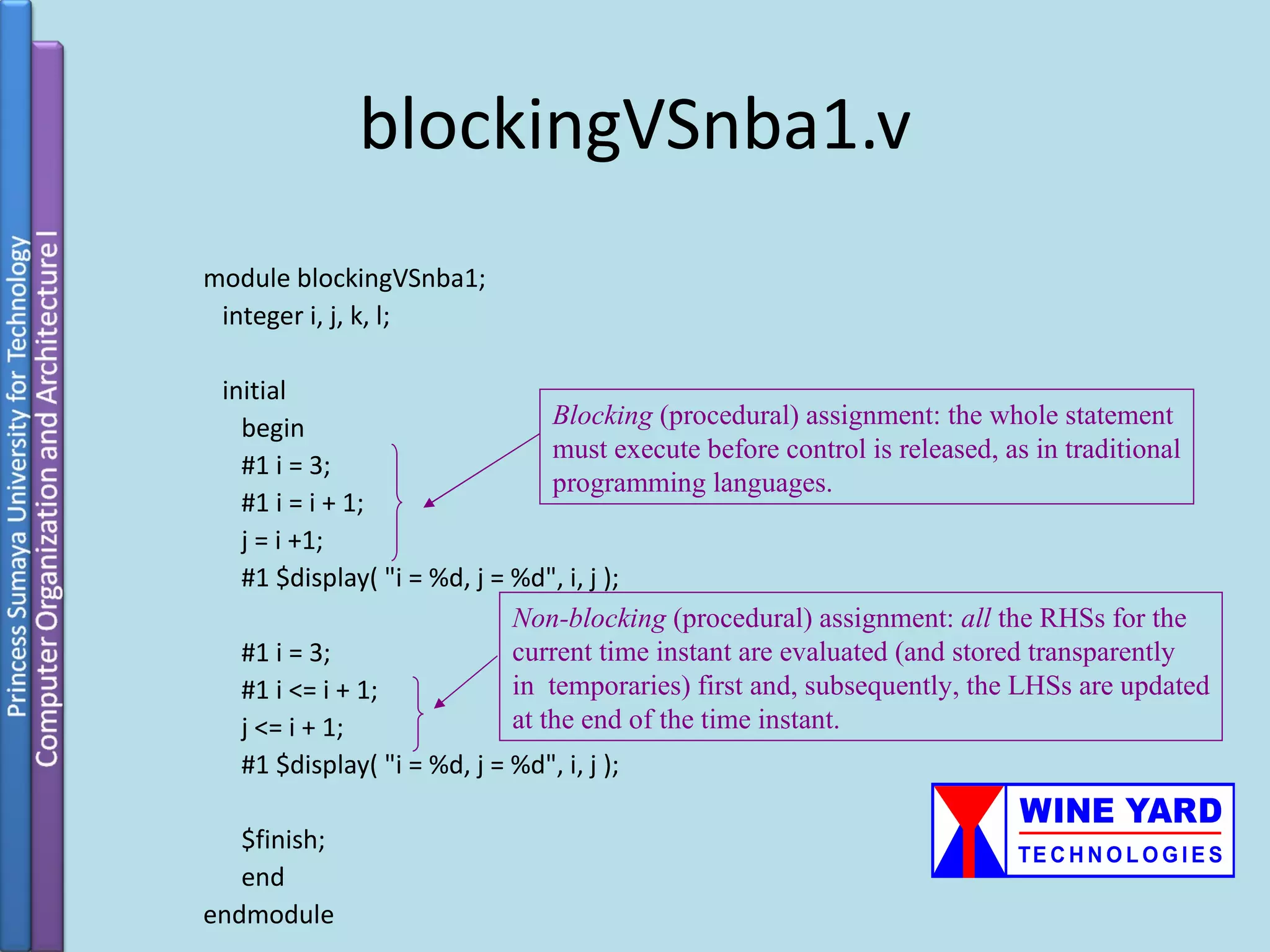
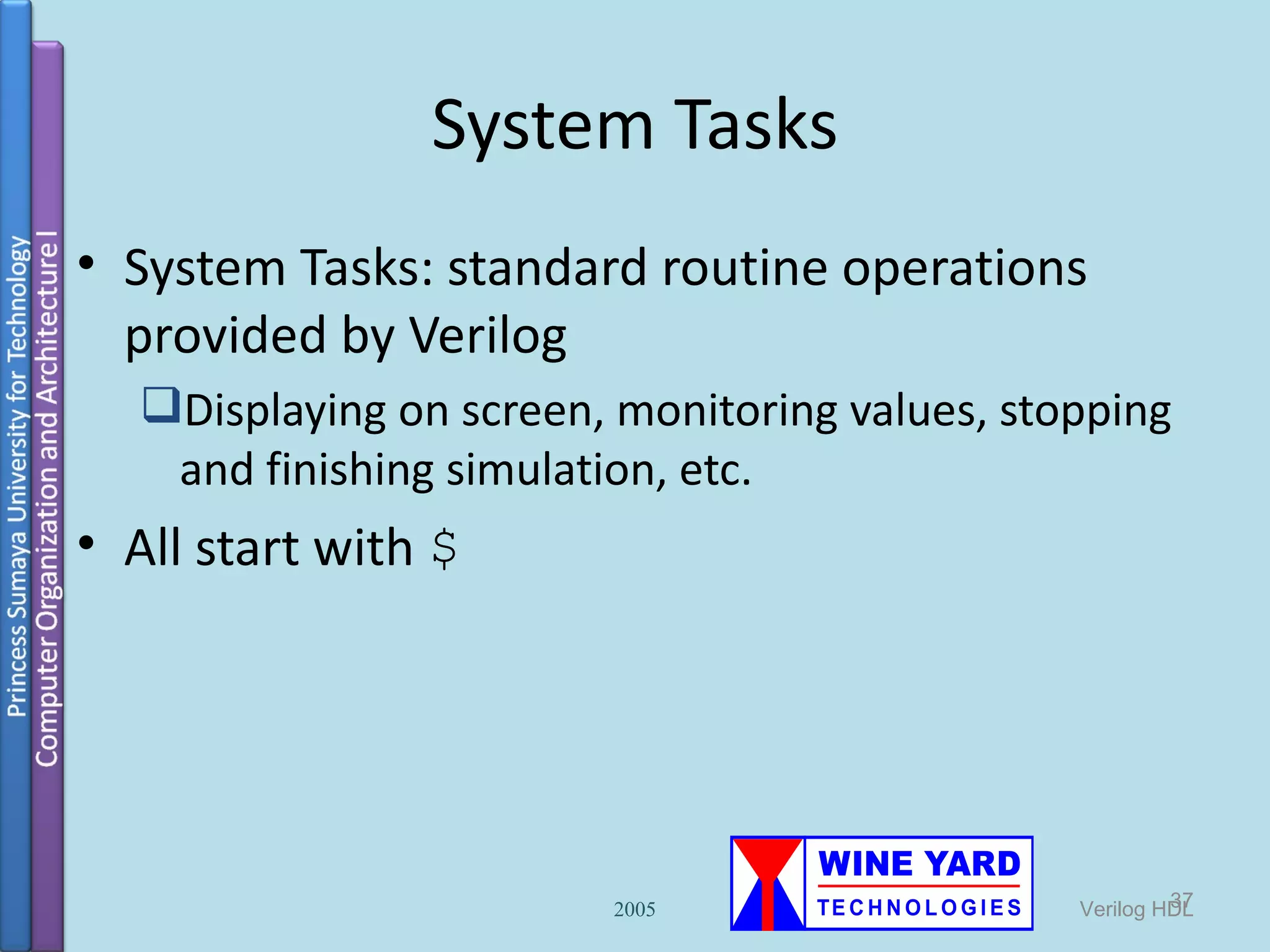
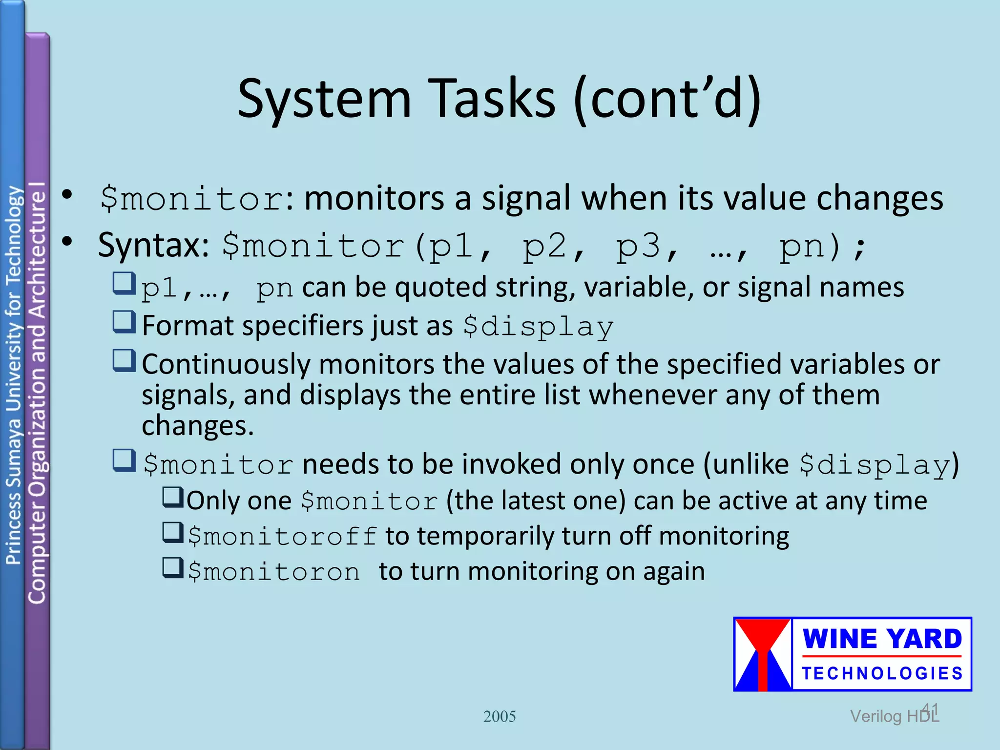
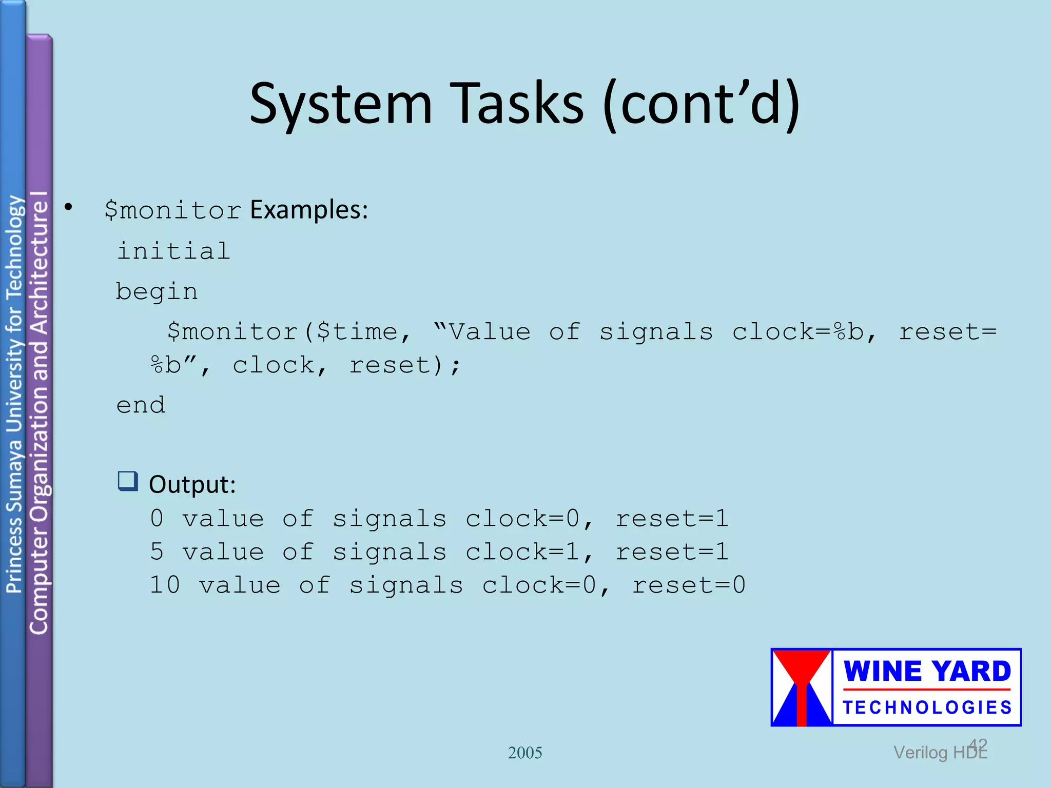
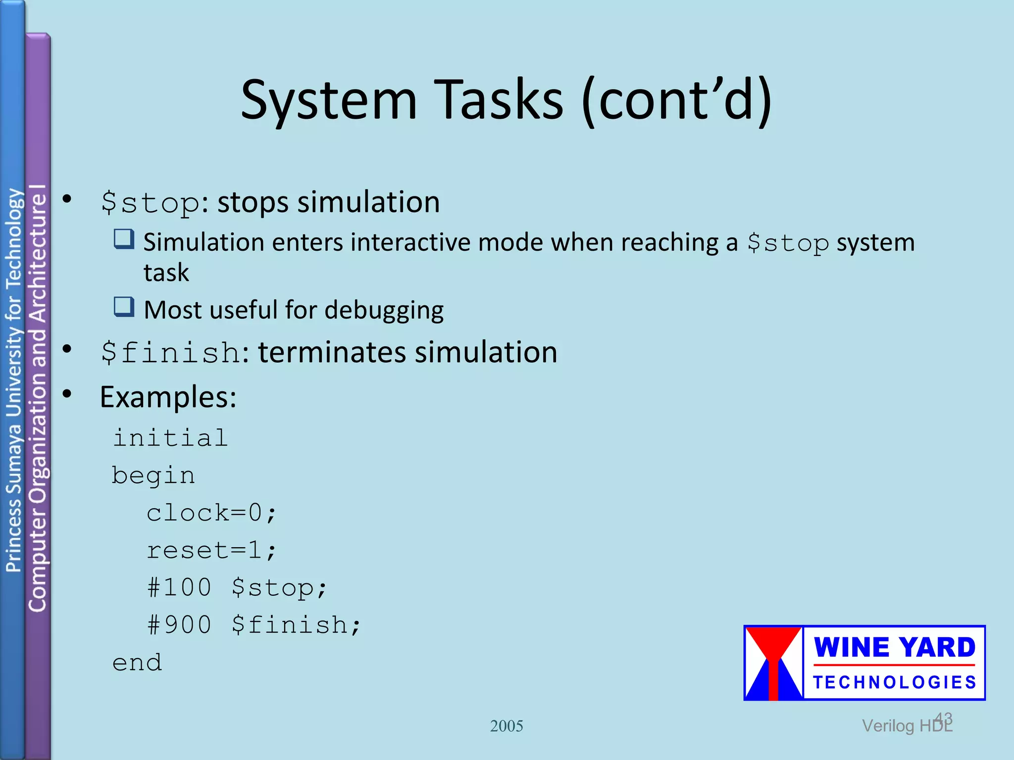
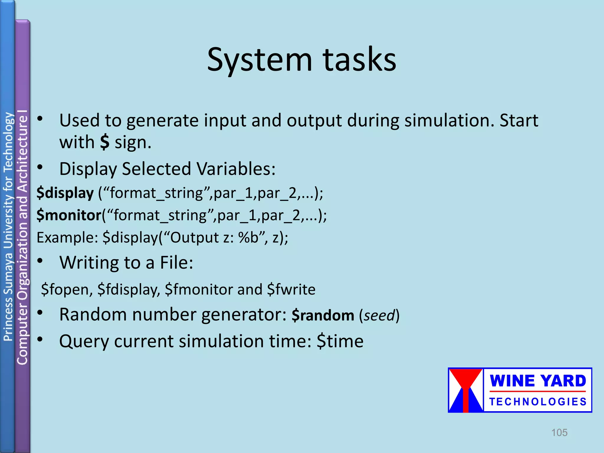
Detailed explanation of arithmetic, relational, and logical operators along with system tasks for output and monitoring.
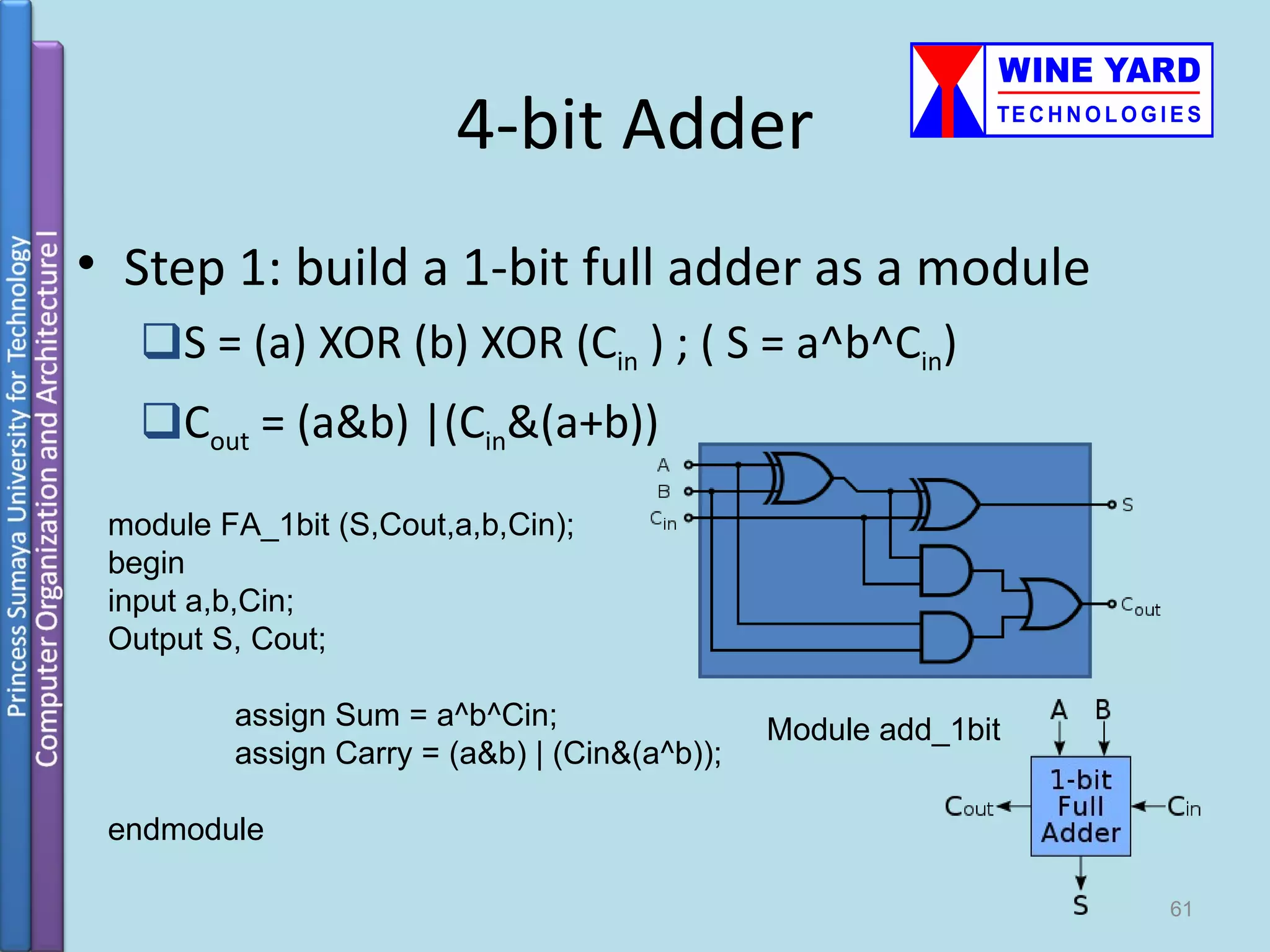
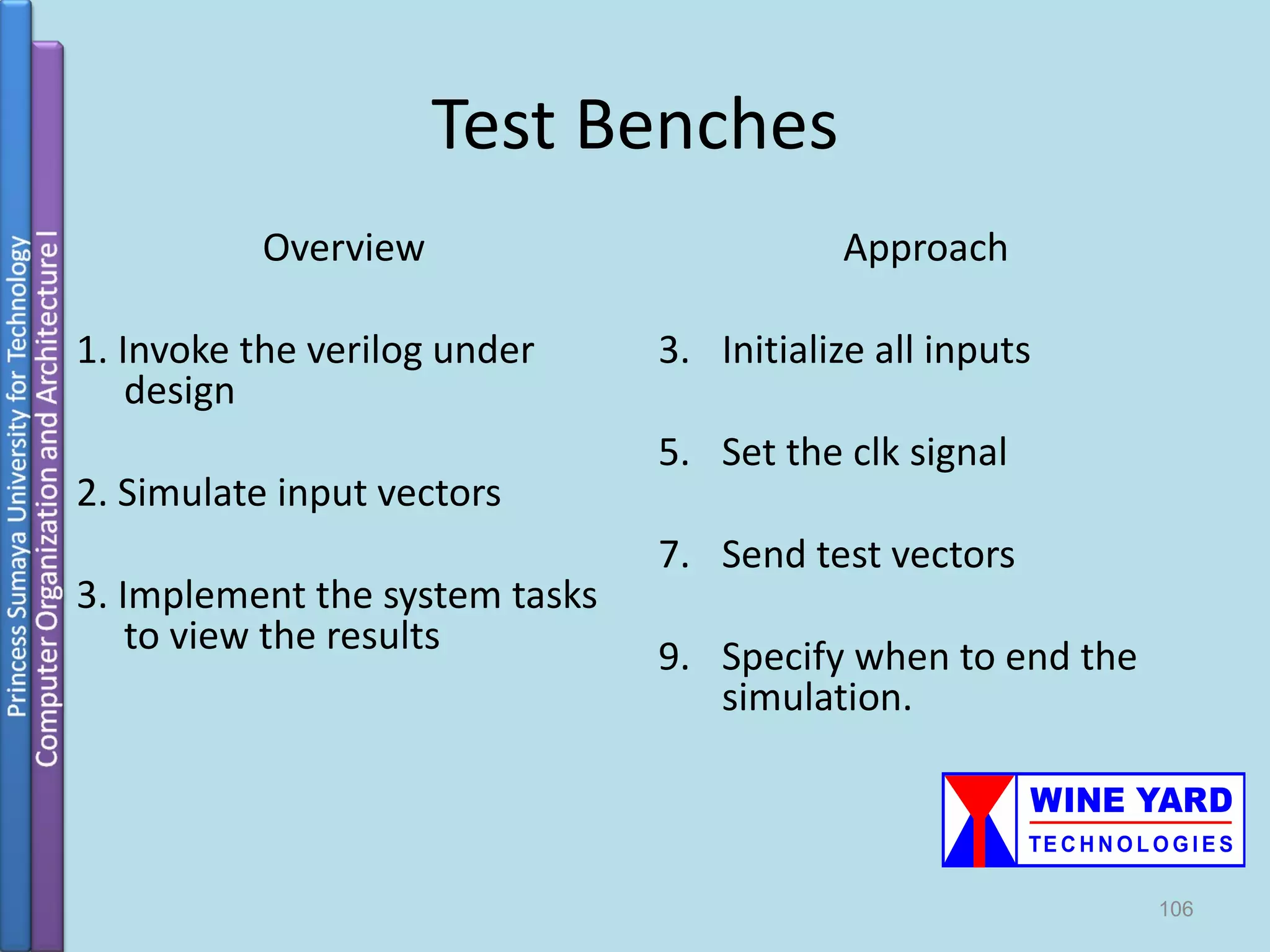
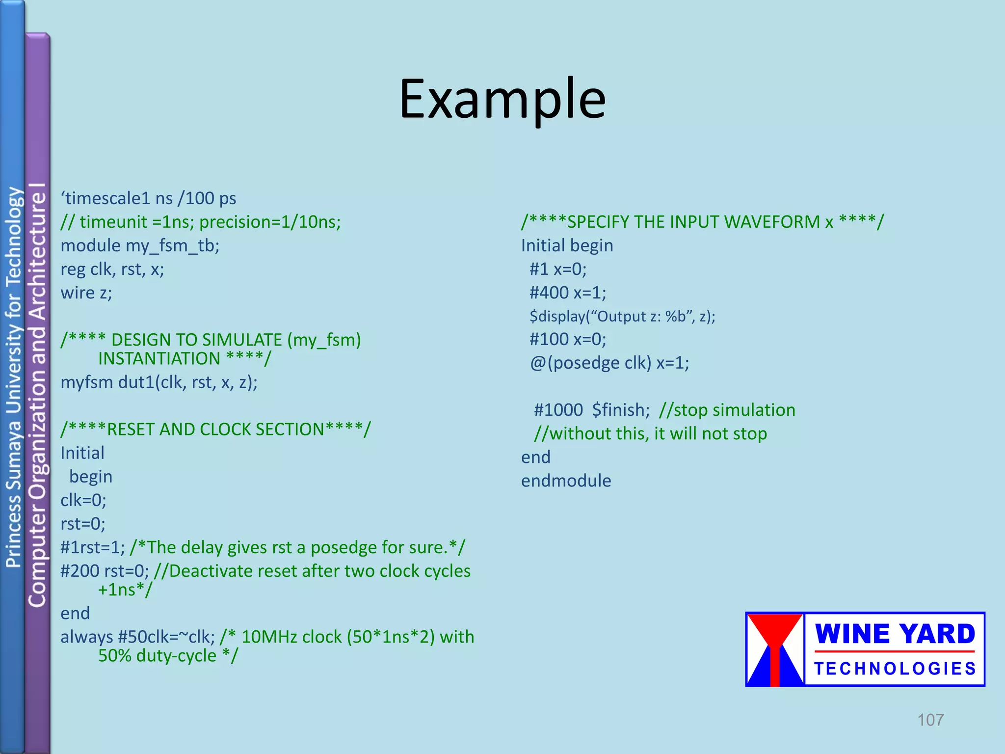
Using Verilog for modeling behavior, finite state machines (FSM), and the methodology of writing test benches. Implementation examples including adders, multiplexers, encoders, and FSMs, with test benches for simulations.