This document outlines an Arduino programming course taught by Md. Ashraful Alam, covering various modules from introduction to programming, digital and analog input, conditionals, loops, and LED control. It details fundamental programming concepts, functions, and examples for beginners, including how to work with different Arduino boards and components. The course incorporates practical coding exercises aimed at enhancing hands-on learning and application of Arduino in hardware projects.


![Module-06: How to use an array Array Declaration: Array is a collection of same type of data. It is a derived data type and has a huge area of use in programming. It’s structure is as below: Array_name[size]={ }; Size means number of elements of the array. For example: Arduino[6]={ 4,5,6,3,8,7}; Here, we have an array named ‘Arduino’ and it has 6 elements. This elements are connected to the 4th,5th,6th,3rd,8th, and 7th pin of the Arduino respectively. The advantage of using array is – we can change the order of the LEDs very easily.](https://image.slidesharecdn.com/arduinoprogramming-201121131145/75/Arduino-programming-51-2048.jpg)
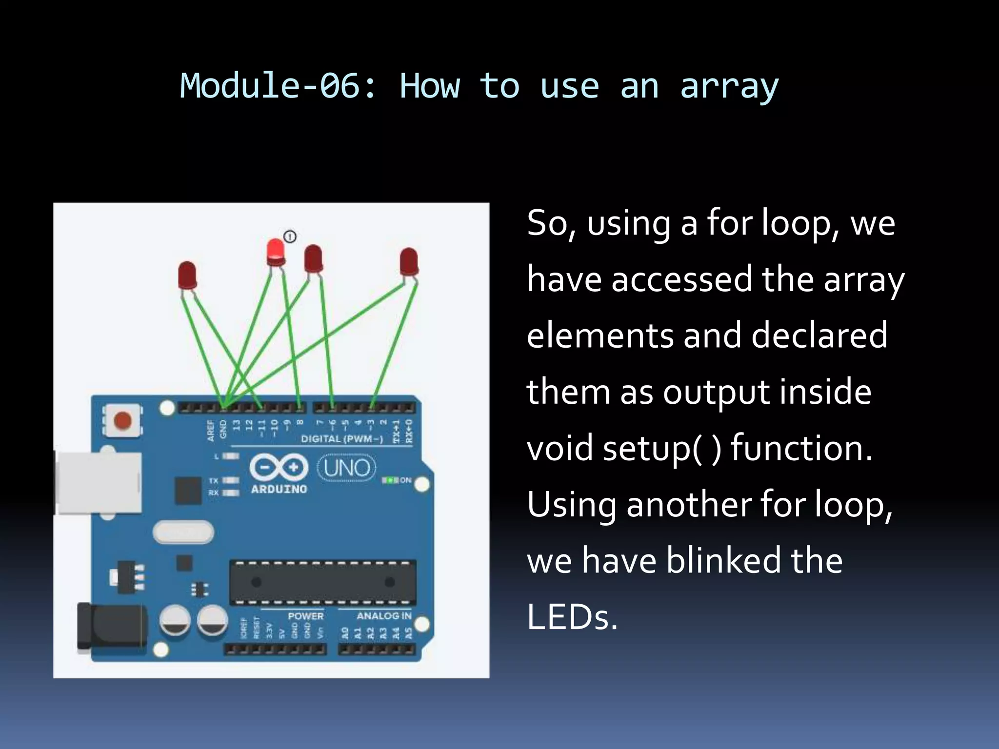
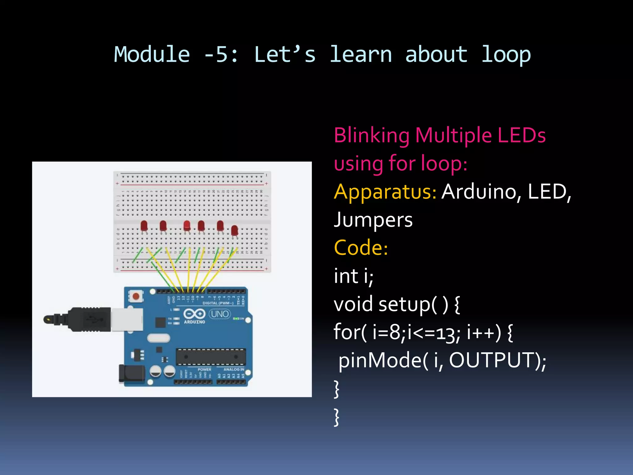
![Module-06: How to use an array Blinking LED using Array: Apparatus: Arduino, LED, Jumpers Code: int array[4]={3,6,8,11}; int i; void setup( ) { for( i=o ; i<4; i++){ pinMode(array[i],OUTPUT); } }](https://image.slidesharecdn.com/arduinoprogramming-201121131145/75/Arduino-programming-52-2048.jpg)
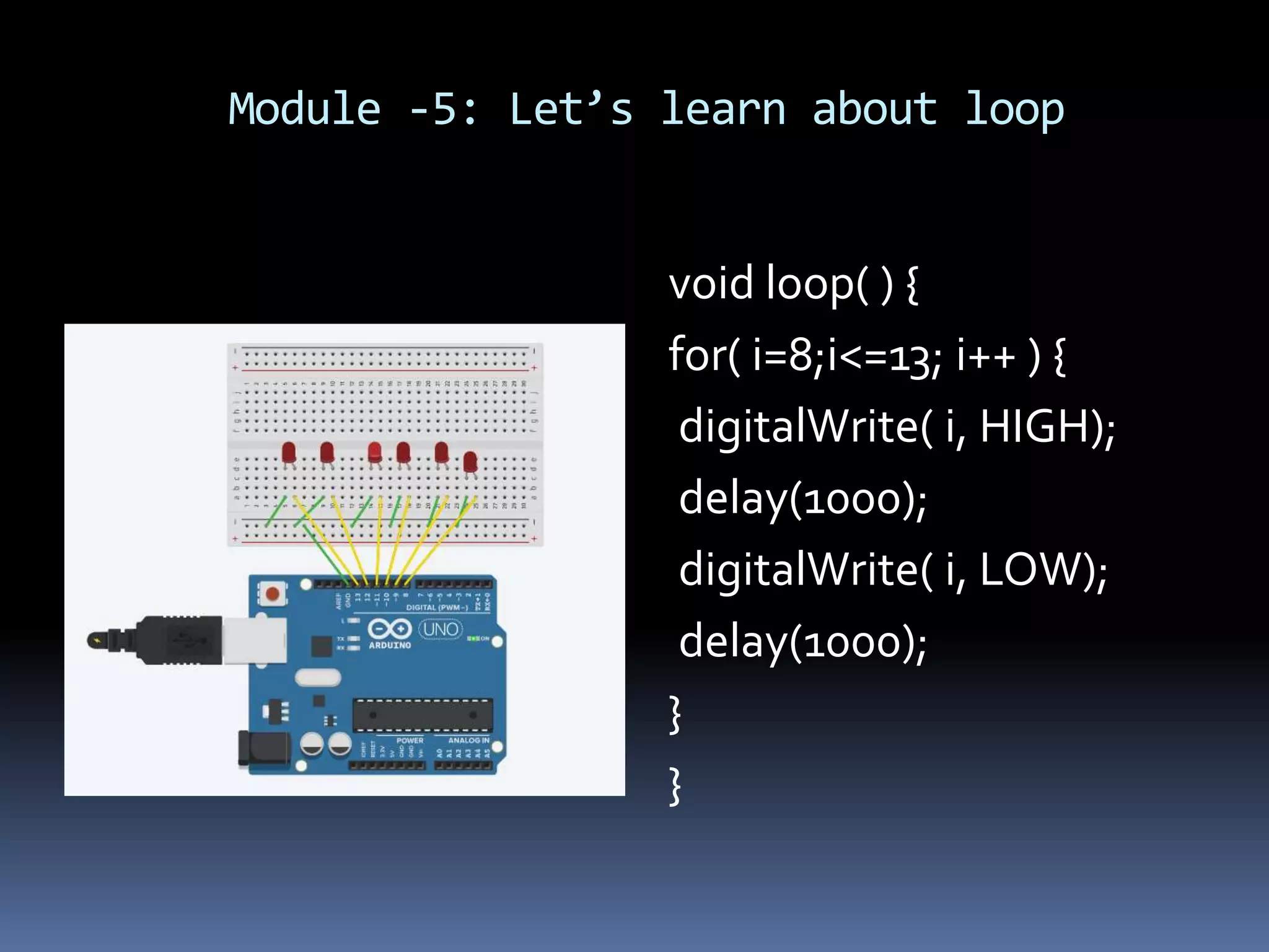
![Module-06: How to use an array void loop( ) { for( i=0; i<4; i++) { digitalWrite( array[i], HIGH); delay(1000); digitalWrite( array[i], LOW); } } Code Explanation: To access array elements, we use array indexing.](https://image.slidesharecdn.com/arduinoprogramming-201121131145/75/Arduino-programming-53-2048.jpg)
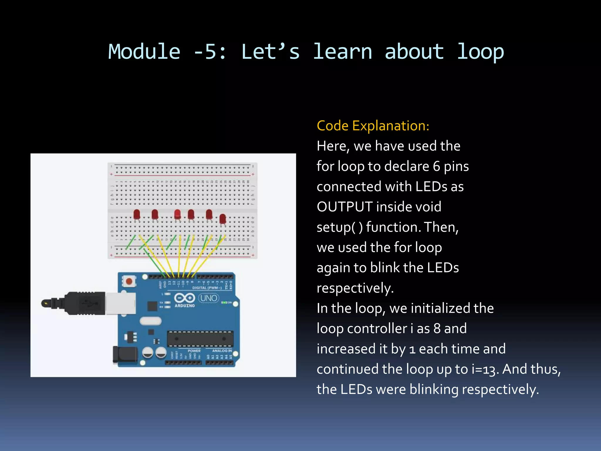
![Module-06: How to use an array The indexing starts from 0 and the last index of an array is (size-1). In this case the last index of the array is 3.We can access the elements using indexing as below: array[0]=3; array[1]=6; array[2]=8; array[3]=11;](https://image.slidesharecdn.com/arduinoprogramming-201121131145/75/Arduino-programming-54-2048.jpg)